PWM and PFM Operation of DC/DC Converters ... - next!-Community
PWM and PFM Operation of DC/DC Converters ... - next!-Community
PWM and PFM Operation of DC/DC Converters ... - next!-Community

Create successful ePaper yourself
Turn your PDF publications into a flip-book with our unique Google optimized e-Paper software.
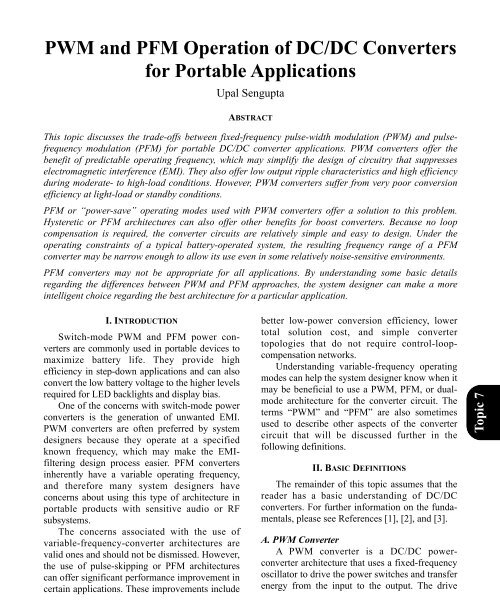
<strong>PWM</strong> <strong>and</strong> <strong>PFM</strong> <strong>Operation</strong> <strong>of</strong> <strong>DC</strong>/<strong>DC</strong> <strong>Converters</strong><br />
for Portable Applications<br />
Upal Sengupta<br />
ABSTRACT<br />
This topic discusses the trade-<strong>of</strong>fs between fixed-frequency pulse-width modulation (<strong>PWM</strong>) <strong>and</strong> pulsefrequency<br />
modulation (<strong>PFM</strong>) for portable <strong>DC</strong>/<strong>DC</strong> converter applications. <strong>PWM</strong> converters <strong>of</strong>fer the<br />
benefit <strong>of</strong> predictable operating frequency, which may simplify the design <strong>of</strong> circuitry that suppresses<br />
electromagnetic interference (EMI). They also <strong>of</strong>fer low output ripple characteristics <strong>and</strong> high efficiency<br />
during moderate- to high-load conditions. However, <strong>PWM</strong> converters suffer from very poor conversion<br />
efficiency at light-load or st<strong>and</strong>by conditions.<br />
<strong>PFM</strong> or “power-save” operating modes used with <strong>PWM</strong> converters <strong>of</strong>fer a solution to this problem.<br />
Hysteretic or <strong>PFM</strong> architectures can also <strong>of</strong>fer other benefits for boost converters. Because no loop<br />
compensation is required, the converter circuits are relatively simple <strong>and</strong> easy to design. Under the<br />
operating constraints <strong>of</strong> a typical battery-operated system, the resulting frequency range <strong>of</strong> a <strong>PFM</strong><br />
converter may be narrow enough to allow its use even in some relatively noise-sensitive environments.<br />
<strong>PFM</strong> converters may not be appropriate for all applications. By underst<strong>and</strong>ing some basic details<br />
regarding the differences between <strong>PWM</strong> <strong>and</strong> <strong>PFM</strong> approaches, the system designer can make a more<br />
intelligent choice regarding the best architecture for a particular application.<br />
I. INTRODUCTION<br />
Switch-mode <strong>PWM</strong> <strong>and</strong> <strong>PFM</strong> power converters<br />
are commonly used in portable devices to<br />
maximize battery life. They provide high<br />
efficiency in step-down applications <strong>and</strong> can also<br />
convert the low battery voltage to the higher levels<br />
required for LED backlights <strong>and</strong> display bias.<br />
One <strong>of</strong> the concerns with switch-mode power<br />
converters is the generation <strong>of</strong> unwanted EMI.<br />
<strong>PWM</strong> converters are <strong>of</strong>ten preferred by system<br />
designers because they operate at a specified<br />
known frequency, which may make the EMIfiltering<br />
design process easier. <strong>PFM</strong> converters<br />
inherently have a variable operating frequency,<br />
<strong>and</strong> therefore many system designers have<br />
concerns about using this type <strong>of</strong> architecture in<br />
portable products with sensitive audio or RF<br />
subsystems.<br />
The concerns associated with the use <strong>of</strong><br />
variable-frequency-converter architectures are<br />
valid ones <strong>and</strong> should not be dismissed. However,<br />
the use <strong>of</strong> pulse-skipping or <strong>PFM</strong> architectures<br />
can <strong>of</strong>fer significant performance improvement in<br />
certain applications. These improvements include<br />
better low-power conversion efficiency, lower<br />
total solution cost, <strong>and</strong> simple converter<br />
topologies that do not require control-loopcompensation<br />
networks.<br />
Underst<strong>and</strong>ing variable-frequency operating<br />
modes can help the system designer know when it<br />
may be beneficial to use a <strong>PWM</strong>, <strong>PFM</strong>, or dualmode<br />
architecture for the converter circuit. The<br />
terms “<strong>PWM</strong>” <strong>and</strong> “<strong>PFM</strong>” are also sometimes<br />
used to describe other aspects <strong>of</strong> the converter<br />
circuit that will be discussed further in the<br />
following definitions.<br />
II. BASIC DEFINITIONS<br />
The remainder <strong>of</strong> this topic assumes that the<br />
reader has a basic underst<strong>and</strong>ing <strong>of</strong> <strong>DC</strong>/<strong>DC</strong><br />
converters. For further information on the fundamentals,<br />
please see References [1], [2], <strong>and</strong> [3].<br />
A. <strong>PWM</strong> Converter<br />
A <strong>PWM</strong> converter is a <strong>DC</strong>/<strong>DC</strong> powerconverter<br />
architecture that uses a fixed-frequency<br />
oscillator to drive the power switches <strong>and</strong> transfer<br />
energy from the input to the output. The drive<br />
Topic 7
Topic 7<br />
signal used is constant in frequency but varies in<br />
its duty cycle (ratio <strong>of</strong> power-FET on time to the<br />
total switching period). The clock frequency is<br />
fixed <strong>and</strong> the pulse width <strong>of</strong> each clock cycle is<br />
adjusted based on operating conditions. Hence,<br />
this approach is referred to as “pulse-width<br />
modulation,” or “<strong>PWM</strong>.”<br />
B. <strong>PFM</strong> Converter<br />
A <strong>PFM</strong> converter is an alternative <strong>DC</strong>/<strong>DC</strong><br />
power-converter architecture that uses a variablefrequency<br />
clock to drive the power switches <strong>and</strong><br />
transfer energy from the input to the output.<br />
Because the drive signal’s frequency is directly<br />
controlled to regulate the output voltage, this<br />
architecture is referred to as “pulse-frequency<br />
modulation,” or “<strong>PFM</strong>.” <strong>DC</strong>/<strong>DC</strong> converters with<br />
constant-on-time or constant-<strong>of</strong>f-time control are<br />
typical examples <strong>of</strong> the <strong>PFM</strong> architecture.<br />
C. Hysteretic Converter<br />
A hysteretic converter is a simple method for<br />
control <strong>of</strong> a <strong>DC</strong>/<strong>DC</strong> conversion circuit in which<br />
the power FET is turned on <strong>and</strong> <strong>of</strong>f based on the<br />
output-voltage changes sensed by the converter.<br />
This architecture is sometimes also referred to as a<br />
“ripple regulator” or “bang-bang controller”<br />
because it continuously shuttles the output voltage<br />
back <strong>and</strong> forth to just above or below the ideal<br />
setpoint. As in most comparator-based circuits,<br />
hysteresis is used to maintain predictable<br />
operation <strong>and</strong> to avoid switch chatter. Because the<br />
hysteretic architecture varies the drive signal to<br />
the power FETs based on the operating conditions<br />
<strong>of</strong> the circuit, the switching frequency is not<br />
constant. The hysteretic approach is therefore one<br />
type <strong>of</strong> <strong>PFM</strong> architecture.<br />
D. Pulse-Skipping/“Power-Save” Mode<br />
This is a secondary control mode used with<br />
some <strong>PWM</strong>-converter architectures especially for<br />
portable or low-power applications. When a<br />
<strong>PWM</strong> converter operates at moderate- to highload<br />
currents, it runs in continuous conduction<br />
mode. As the load current decreases, the converter<br />
may switch to discontinuous mode. At very light<br />
loads, the converter goes into pulse-skipping or<br />
power-save mode by intermittently turning <strong>of</strong>f the<br />
internal oscillator <strong>and</strong> re-enabling it only as<br />
needed to maintain the output regulation. Because<br />
this further “modulates” the switching frequency,<br />
this mode <strong>of</strong> operation is also sometimes referred<br />
to as “<strong>PFM</strong> mode.” It does not necessarily mean<br />
that the fundamental operation <strong>of</strong> the converter<br />
uses the <strong>PFM</strong> architecture.<br />
E. LED Brightness Control<br />
The brightness <strong>of</strong> an LED backlight is<br />
typically controlled by setting the current through<br />
the LED string. Typical levels used in portable<br />
devices are 20 to 25 mA for higher brightness or<br />
5 to 10 mA for lower brightness. Low-power modes<br />
may use average currents <strong>of</strong> 1 mA or less.<br />
F. Analog Dimming<br />
LED brightness can also be controlled by<br />
directly changing the continuous current through<br />
the LED. The TPS61060 family <strong>of</strong> devices<br />
implements a “digital-dimming” feature that<br />
allows a host processor to digitally control LED<br />
brightness by sending a comm<strong>and</strong> to the IC. The<br />
digital comm<strong>and</strong> from the processor actually sets<br />
an analog feedback voltage within the IC <strong>and</strong><br />
controls brightness without the need for <strong>PWM</strong><br />
enable/disable control. Analog dimming can also<br />
be applied to most common LED drivers by<br />
simply varying the value <strong>of</strong> an external resistor.<br />
Analog dimming may be preferred for very noisesensitive<br />
applications. However, for some types <strong>of</strong><br />
LEDs, the LED illumination color varies slightly<br />
with changes in bias-current that can result in<br />
some color shift as the brightness is decreased.<br />
G. <strong>PWM</strong> Dimming<br />
<strong>PWM</strong> dimming is a method <strong>of</strong> controlling<br />
LED brightness by turning the LED current on<br />
<strong>and</strong> <strong>of</strong>f at a rate faster than noticeable by the<br />
human eye. The converter used to drive the LED<br />
string is turned on <strong>and</strong> <strong>of</strong>f at a rate typically<br />
ranging from around 100 Hz up to a few kilohertz.<br />
When the converter is on, the current flowing<br />
through the LEDs is always the same, which<br />
prevents the perception <strong>of</strong> a color shift in the<br />
LEDs. By varying the duty cycle (hence <strong>PWM</strong>) <strong>of</strong><br />
the dimming control signal, the average current<br />
<strong>and</strong> thus the perceived brightness <strong>of</strong> the LED<br />
backlight can be precisely controlled.
The term “<strong>PWM</strong>” in this particular case refers<br />
to the modulation <strong>of</strong> the enable signal to the<br />
converter IC, which turns the LED driver on <strong>and</strong><br />
<strong>of</strong>f as required to set a specific average brightness.<br />
The <strong>PWM</strong> dimming frequency is typically in the<br />
range <strong>of</strong> around 100 Hz to several kilohertz. It<br />
should not be confused with the switching<br />
frequency <strong>of</strong> the converter itself, which is typically<br />
in the range <strong>of</strong> hundreds <strong>of</strong> kilohertz to a few<br />
megahertz. <strong>PWM</strong> dimming may be used with either<br />
<strong>PWM</strong>- or <strong>PFM</strong>-converter architectures. Fig. 1<br />
illustrates a 50% <strong>PWM</strong> dimming control applied<br />
to the TPS61042 boost converter.<br />
VSW<br />
5 V/div<br />
VOUT<br />
500 mV/div<br />
LED Current<br />
20 mA/div<br />
Time Base - 25 µs/div<br />
Fig. 1. Typical switching waveforms <strong>of</strong> TPS61042<br />
converter (4-LED string).<br />
From the switch voltage (V SW ) trace, it can be<br />
seen that the converter itself completes 11 switching<br />
cycles within 50 µs. Thus, the actual switching<br />
frequency <strong>of</strong> the converter under these conditions<br />
is approximately<br />
11<br />
f SW = = 220 kHz.<br />
−6<br />
50 • 10<br />
The converter is turned on for 50 µs <strong>and</strong> <strong>of</strong>f for<br />
50 µs; in other words, the <strong>PWM</strong> dimming frequency<br />
is 10 kHz with a duty cycle <strong>of</strong> 50%. When<br />
the converter is on, it generates an average LED<br />
current <strong>of</strong> approximately 20 mA. Since the duty<br />
cycle is 50%, the long-term, average LED current<br />
over multiple cycles is 10 mA. The visible<br />
brightness <strong>of</strong> this LED backlight would appear<br />
approximately the same as if it were operated at a<br />
constant 10-mA drive current.<br />
H. Switch-Mode-Converter Operating Losses<br />
There are several types <strong>of</strong> switch-modeconverter<br />
loss. “Loss” in this case refers to any<br />
area in which energy is drawn from the input<br />
without correspondingly being transferred to the<br />
output. An ideal converter operates at 100%<br />
efficiency <strong>and</strong> has zero loss. For the purposes <strong>of</strong><br />
this topic, four types <strong>of</strong> loss are considered:<br />
• MOSFET dynamic losses—These can be<br />
divided into gate-drive <strong>and</strong> switching losses.<br />
Gate-drive losses are caused by the energy used<br />
to charge <strong>and</strong> discharge the MOSFET’s gate<br />
capacitance, <strong>and</strong> are highest when the FETs are<br />
quickly turned on <strong>and</strong> <strong>of</strong>f at high frequency.<br />
Switching losses occur as the MOSFET<br />
transitions through its linear operating range,<br />
<strong>and</strong> current flows through the drain-source<br />
channel while there is significant drain-source<br />
differential voltage. An ideal MOSFET would<br />
have zero gate capacitance <strong>and</strong> infinitely fast<br />
switching time, resulting in no switching losses.<br />
• MOSFET conduction losses—These are<br />
primarily ohmic losses caused by passing high<br />
currents through the nonzero channel resistance<br />
<strong>of</strong> the power-switching elements. An ideal<br />
MOSFET would have zero on resistance,<br />
resulting in no conduction losses.<br />
• Passive component losses—For inductors,<br />
these can take the form <strong>of</strong> conduction<br />
(wire/winding) losses or magnetic core losses.<br />
For capacitors, losses are typically associated<br />
with the equivalent series resistance (ESR) <strong>of</strong><br />
the component <strong>and</strong> are determined by the<br />
choice <strong>of</strong> external component, operating<br />
frequency, <strong>and</strong> load current.<br />
• Converter IC losses—These are from the<br />
amount <strong>of</strong> energy required to operate the<br />
power-converter IC itself. These losses include<br />
internal bias currents for amplifiers, comparators,<br />
<strong>and</strong> references, but they are typically<br />
dominated by the internal oscillator <strong>and</strong> drive<br />
circuits for most <strong>PWM</strong> converters.<br />
During relatively high-load conditions, the<br />
loss associated with converter ICs is relatively<br />
small compared to the other types <strong>of</strong> losses from<br />
switch-mode converters. However, as the load<br />
current decreases, especially in very light-load or<br />
st<strong>and</strong>by conditions, the losses associated with<br />
Topic 7
Topic 7<br />
MOSFET conduction <strong>and</strong> passive components<br />
diminish toward zero while MOSFET dynamic<br />
losses <strong>and</strong> converter-IC losses remain relatively<br />
constant for a <strong>PWM</strong> converter. Thus, at very light<br />
loads, the ability to reduce the converter’s<br />
quiescent current as well as the gate-drive loss is a<br />
significant factor in maintaining high efficiency.<br />
Reducing the switching frequency under lightload<br />
conditions can accomplish both <strong>of</strong> these<br />
goals. There are numerous articles <strong>and</strong> textbooks<br />
that give a more complete treatment <strong>of</strong> efficiency<br />
analysis <strong>and</strong> sources <strong>of</strong> loss for switch-mode<br />
converters. Refer to References [1], [2], <strong>and</strong> [3]<br />
for additional information.<br />
III. DUAL-MODE BUCK-CONVERTER<br />
ARCHITECTURE<br />
One <strong>of</strong> the characteristics <strong>of</strong> an ideal switchmode<br />
converter is that it provides high efficiency<br />
under all operating conditions. In practice,<br />
however, this may become very difficult in a<br />
portable product that operates across a wide range<br />
<strong>of</strong> load currents. Many portable applications have<br />
operating modes such as low-power or “sleep”<br />
modes in addition to high-current, fully on<br />
operating modes. A typical h<strong>and</strong>held device may<br />
draw 1 mA or less <strong>of</strong> load current in sleep or<br />
st<strong>and</strong>by mode while drawing over 1 A in its<br />
maximum-performance operating condition. The<br />
classical fixed-frequency, or <strong>PWM</strong>, operating<br />
mode <strong>of</strong>fers good performance under most<br />
operating conditions. However, the basic<br />
operation <strong>of</strong> the power-converter IC in this mode<br />
usually draws some measurable amount <strong>of</strong> current<br />
ranging up to a few milliamps. If the converter’s<br />
load (a subsystem such as a microprocessor or<br />
memory) is drawing more than 100 mA, then the<br />
current drawn by the converter itself may not<br />
significantly affect the total efficiency <strong>of</strong> the<br />
power-conversion process. However, as the<br />
system load decreases (for example, in st<strong>and</strong>by or<br />
low-power operation), the conversion efficiency<br />
can decrease significantly because the converter’s<br />
quiescent current becomes a significant portion <strong>of</strong><br />
the total current drawn.<br />
To improve efficiency at light-load operation,<br />
the operating current <strong>of</strong> the converter circuit must<br />
be reduced. A <strong>PWM</strong> converter requires an internal<br />
oscillator circuit. If the oscillator is always on, it<br />
will allow fast transient response to input <strong>and</strong> load<br />
variations. However, this oscillator is one <strong>of</strong> the<br />
main sources <strong>of</strong> current consumption within the<br />
IC. Shutting down the oscillator <strong>and</strong> some <strong>of</strong> the<br />
internal drive circuitry inside the converter IC can<br />
save an appreciable amount <strong>of</strong> operating current.<br />
Under light-load conditions, a pulse-skipping<br />
technique (power-save or <strong>PFM</strong> mode) is used.<br />
Power-save mode is entered when the inductor<br />
current (sensed within the IC) falls below a<br />
predefined threshold. In this mode <strong>of</strong> operation,<br />
the converter switches current from the input to<br />
the load only as <strong>of</strong>ten as needed to prevent the<br />
output from falling out <strong>of</strong> regulation.<br />
There are some performance trade-<strong>of</strong>fs when<br />
using the power-save mode. The transient<br />
response <strong>of</strong> the converter may be slower <strong>and</strong> the<br />
output voltage ripple may be higher. Some<br />
increase in output ripple is observed because <strong>of</strong><br />
the tolerance b<strong>and</strong> used to sense when the power<br />
switches need to be turned on again. If a narrower<br />
tolerance b<strong>and</strong> is used, the converter switches<br />
more frequently, which reduces the benefit <strong>of</strong> the<br />
power-save mode. Thus, there is a direct trade-<strong>of</strong>f<br />
between improving low-power efficiency <strong>and</strong><br />
increased output ripple in power-save mode.<br />
Selectively disabling the oscillator circuit <strong>and</strong><br />
pulsing the power switches only as needed to<br />
maintain regulation can reduce the quiescent<br />
current <strong>of</strong> the IC from a few milliamperes down to<br />
several microamperes. The resulting improvement<br />
in efficiency can be seen at light loads in Fig. 2.<br />
Efficiency – %<br />
100<br />
90<br />
V OUT2 = 3.3 V<br />
80 V IN = 3.6 V<br />
V IN = 3.6 V<br />
70<br />
60<br />
V IN = 5 V<br />
V IN = 5 V<br />
50<br />
40<br />
30<br />
Power-Save Mode Forced-<strong>PWM</strong> Mode<br />
MODE/DATA pin = 0 MODE/DATA pin = 1<br />
20<br />
10<br />
0<br />
0.01 0.1 1 10 100 1000<br />
I OUT – mA<br />
Fig. 2. TPS62400 conversion efficiency for <strong>PWM</strong><br />
<strong>and</strong> power-save modes.
This figure illustrates the power-conversion<br />
efficiency <strong>of</strong> the TPS62400 <strong>DC</strong>/<strong>DC</strong> converter<br />
when it operates in fixed-frequency <strong>PWM</strong> mode<br />
as well as in power-save (<strong>PFM</strong>) mode at light-load<br />
levels. While a fixed-frequency <strong>PWM</strong> mode can<br />
maintain good efficiency above 100 mA, the use<br />
<strong>of</strong> a pulse-skipping <strong>PFM</strong> mode will allow for<br />
converter efficiency in the range <strong>of</strong> 80 to 90%<br />
even at load currents below 1 mA. If the converter<br />
was left in <strong>PWM</strong> mode at this light-load level, its<br />
own operating current would be significantly<br />
higher than the load current, resulting in very poor<br />
conversion efficiency (well under 30%, as shown).<br />
Under very light-load conditions, the<br />
converter’s output capacitor can maintain the<br />
output voltage for some period <strong>of</strong> time between<br />
switching pulses. In the ideal case, the oscillator<br />
could be turned completely <strong>of</strong>f at a no-load<br />
condition <strong>and</strong> the output voltage would remain<br />
constant due to the charged state <strong>of</strong> the output<br />
capacitor. In reality, <strong>of</strong> course, some parasitic<br />
losses occur, <strong>and</strong> the circuit requires at least<br />
occasional pulsing <strong>of</strong> the power switches to<br />
maintain the output voltage in regulation. Fig. 3<br />
shows pulse skipping <strong>of</strong> the TPS62350 <strong>DC</strong>/<strong>DC</strong><br />
converter at different load conditions. This device<br />
has two power-saving modes: the light-load <strong>PFM</strong><br />
(L<strong>PFM</strong>) mode <strong>and</strong> the fast-<strong>PFM</strong> (F<strong>PFM</strong>) mode—<br />
described in more detail later. It can be seen that<br />
the power switch is pulsed more frequently at<br />
higher-load levels (F<strong>PFM</strong> mode). Note that the<br />
units on the x <strong>and</strong> y axes are different for Figs. 3a<br />
<strong>and</strong> 3b. At still higher loads, the converter resumes<br />
constant-frequency (<strong>PWM</strong>-mode) operation with<br />
the oscillator fully on.<br />
During load transients, any voltage regulator<br />
will exhibit some amount <strong>of</strong> overshoot during a<br />
high-to-low load transient or undershoot during a<br />
low-to-high load transient. In the case <strong>of</strong> a<br />
converter that has entered power-save mode, the<br />
load level is already low, so the <strong>next</strong> significant<br />
load transient that can occur is from low to high<br />
current. In an application, this corresponds to<br />
“waking up” from sleep mode to active mode, for<br />
example. When this occurs, the increased load on<br />
the regulator output will result in output-voltage sag<br />
until the converter loop has a chance to respond.<br />
To anticipate the output sag that may result in<br />
going from a light-load to a high-load operating<br />
condition, a technique called “dynamic voltage<br />
positioning” is available with the TPS62400.<br />
During the power-save mode, the output-voltage<br />
setpoint is increased slightly (for example, by 1%)<br />
to anticipate the instantaneous negative-going<br />
transient that will occur when the load is suddenly<br />
stepped higher. This prevents the output voltage<br />
from falling below its desired window <strong>of</strong> regulation<br />
during the initial load transient. Details <strong>of</strong> the<br />
voltage positioning technique are provided in the<br />
TPS62400 datasheet (see Reference [4]).<br />
V O I L<br />
20 mV/div with 1.35-V Offset 200 mA/div<br />
V I = 3.6 V<br />
V O = 1.35 V<br />
I O = 40 mA<br />
L = 1 µH<br />
C O = 10 µF<br />
F<strong>PFM</strong> Mode<br />
V O I L<br />
20 mV/div with 1.05-V Offset 200 mA/div<br />
V I = 3.6 V<br />
V O = 1.05 V<br />
I O = 1 mA<br />
L = 1 µH<br />
C O = 10 µF<br />
L<strong>PFM</strong> Mode<br />
Topic 7<br />
t – Time Base = 2.5 µs/div<br />
t – Time Base = 40 µs/div<br />
a. Fast-<strong>PFM</strong> mode with 40-mA load. b. Light-load <strong>PFM</strong> mode with 1-mA load.<br />
Fig. 3. TPS62350 pulse skipping at 40-mA <strong>and</strong> 1-mA load conditions.
Power-Save Mode<br />
MODE/DATA pin = Low<br />
I<br />
Forced-<strong>PWM</strong> Mode<br />
OUT = 10 mA<br />
MODE/DATA pin =<br />
I =10 mA<br />
High<br />
OUT<br />
V OUT = 1.8 V (20 mV/div)<br />
V OUT = 1.8 V (20 mV/div)<br />
Inductor Current (100 mA/div)<br />
Inductor Current (100 mA/div)<br />
Time Base – 10 µs/div<br />
Time Base – 400 ns/div<br />
a. Light-load V OUT ripple in power-save mode. b. V OUT ripple in forced-<strong>PWM</strong> mode.<br />
Fig. 4. TPS62401 power-save (<strong>PFM</strong>) <strong>and</strong> fixed-frequency (<strong>PWM</strong>) operation waveforms.<br />
Topic 7<br />
Fig. 4a shows the increased output-voltage<br />
ripple <strong>and</strong> periodic switching cycles that occur in<br />
the power-save mode at light loads; it also shows<br />
the slightly higher output-voltage setpoint. Fig. 4b<br />
shows the reduced ripple voltage <strong>and</strong> continuous<br />
switching cycles that occur when the converter is<br />
operated in the forced-<strong>PWM</strong> mode.<br />
An additional enhancement that can be<br />
implemented to balance the trade-<strong>of</strong>f between<br />
good transient response (best in <strong>PWM</strong> mode) <strong>and</strong><br />
low power consumption (best in powersave/L<strong>PFM</strong><br />
mode) is an intermediate or F<strong>PFM</strong><br />
mode as shown for the TPS62350 in Fig. 5. The<br />
user can control the mode <strong>of</strong> operation using I 2 C<br />
comm<strong>and</strong>s to the converter IC. The device will<br />
automatically transition between either the L<strong>PFM</strong><br />
or the F<strong>PFM</strong> power-save mode (based on its<br />
preprogrammed register configuration) <strong>and</strong> the<br />
<strong>PWM</strong> mode as required by the load-current level.<br />
The L<strong>PFM</strong> mode works well for a system that<br />
goes from a high load to a very light load, as in<br />
sleep-mode operation. The L<strong>PFM</strong> control scheme<br />
is based on a fixed inductor peak current. To get a<br />
proper automatic transition between L<strong>PFM</strong> <strong>and</strong><br />
<strong>PWM</strong> operation, the inductor peak current is set<br />
higher than the <strong>PWM</strong> peak-to-peak ripple current.<br />
During the pulse-skipping phase, the converter runs<br />
only its internal reference <strong>and</strong> a comparator to<br />
monitor the output voltage. The advantage <strong>of</strong> L<strong>PFM</strong><br />
is much lower quiescent current <strong>and</strong> higher efficiency<br />
compared with F<strong>PFM</strong> at low output loads.<br />
If appropriately configured, the TPS62350<br />
will automatically transition from <strong>PWM</strong> mode<br />
into F<strong>PFM</strong> mode when the following conditions<br />
are met simultaneously for three or more clock<br />
cycles:<br />
• The output voltage is within its regulation<br />
limits.<br />
• The inductor valley current reaches zero.<br />
Efficiency – %<br />
100<br />
90<br />
80<br />
70<br />
60<br />
50<br />
40<br />
30<br />
20<br />
10<br />
L<strong>PFM</strong>/<strong>PWM</strong><br />
F<strong>PFM</strong>/<strong>PWM</strong><br />
3-MHz <strong>PWM</strong><br />
V I = 3.6 V<br />
V O = 1.5 V<br />
L = 1 µH<br />
C O = 10 µF<br />
0<br />
0.1 1 10 100 1000<br />
I O – Output Current – mA<br />
Fig. 5. L<strong>PFM</strong>, F<strong>PFM</strong>, <strong>and</strong> fixed-frequency <strong>PWM</strong><br />
efficiency <strong>of</strong> TPS62350.
In F<strong>PFM</strong> mode, the converter ramps up the<br />
output voltage by means <strong>of</strong> its <strong>PWM</strong> control loop.<br />
This typically requires several switching cycles.<br />
Once the output voltage falls below the nominal<br />
low-voltage threshold, the PMOS switch is turned<br />
on <strong>and</strong> the device exits power-save mode. During<br />
<strong>PFM</strong> operation, the TPS62350 converter positions<br />
the output voltage slightly higher than the nominal<br />
output voltage during <strong>PWM</strong> operation, allowing<br />
additional headroom for voltage drop during a<br />
load transient from light to heavy load.<br />
TI components that support the power-save<br />
mode also provide a logic input that, if required by<br />
the application, allows the converter to be<br />
operated in forced-<strong>PWM</strong> mode regardless <strong>of</strong> the<br />
load condition. This is useful when the fast<br />
transient response <strong>and</strong> other performance<br />
characteristics <strong>of</strong> the <strong>PWM</strong> mode are more<br />
important than conversion efficiency for specific<br />
operating modes. If the forced-<strong>PWM</strong> mode is not<br />
asserted, the device will auto-switch between<br />
<strong>PWM</strong> <strong>and</strong> power-save/<strong>PFM</strong> modes as required by<br />
the load-current level.<br />
IV. FIXED-FREQUENCY AND HYSTERETIC<br />
BOOST CONVERTERS<br />
The application <strong>of</strong> a fixed-frequency control<br />
architecture provides the same benefits for boostconverter<br />
circuits as for buck-converter circuits.<br />
The fixed operating frequency allows for predictable<br />
design <strong>of</strong> EMI-filtering components, but<br />
variable-frequency-converter architecture can<br />
<strong>of</strong>fer many benefits in boost applications.<br />
Fig. 6 is a block diagram <strong>of</strong> the TPS61020<br />
<strong>PWM</strong>-mode boost converter. Like the converters<br />
previously discussed, the TPS61020 has a powersave<br />
mode for light-load currents, so it can operate<br />
as a variable-frequency device under some load<br />
conditions.<br />
SW<br />
V BAT<br />
Anti-<br />
Ringing<br />
Backgate<br />
Control<br />
V OUT<br />
V OUT<br />
Vmax<br />
Control<br />
Gate<br />
Control<br />
10 kΩ<br />
20 pF<br />
PGND<br />
Regulator<br />
Control Logic<br />
PGND<br />
Error<br />
Amplifier<br />
–<br />
+<br />
+<br />
–<br />
PGND<br />
V REF =<br />
0.5 V<br />
FB<br />
Topic 7<br />
EN<br />
PS<br />
GND<br />
LBI<br />
GND<br />
V REF = 0.5 V<br />
– +<br />
Low-Battery<br />
Comparator<br />
–<br />
+<br />
Oscillator<br />
Temperature<br />
Control<br />
GND<br />
LBO<br />
Fig. 6. Functional block diagram <strong>of</strong> TPS61020 boost converter.
Fig. 7 is a block diagram <strong>of</strong> the TPS61042<br />
boost converter. Note that this device does not<br />
have an internal oscillator. As discussed earlier, a<br />
conventional <strong>PWM</strong> converter uses its clock to<br />
generate a drive signal to the power FETs. (This<br />
drive signal may be gated <strong>of</strong>f or further controlled<br />
by several other factors, as described in the<br />
references listed at the end <strong>of</strong> this topic.)<br />
The TPS61042 shown in Fig. 7 uses<br />
hysteretic-converter architecture that operates in a<br />
different manner. As previously mentioned, this<br />
architecture is sometimes called a “bang-bang<br />
controller.” In this circuit, the main power switch,<br />
Q1, is turned on until a fixed peak current is<br />
reached. When the switch is turned on, the<br />
inductor current begins to increase. The ramp time<br />
to reach the peak threshold limit is dependent on<br />
the inductor value, L, <strong>and</strong> the other operating<br />
conditions <strong>of</strong> the circuit. Once the peak current is<br />
reached, the switch is turned <strong>of</strong>f <strong>and</strong> the energy is<br />
transferred to the output as in any boost converter.<br />
The switch is turned on again when the feedback<br />
pin (FB), or sense voltage, falls below the internal<br />
reference point.<br />
This type <strong>of</strong> converter therefore essentially<br />
self-oscillates based on the measurement <strong>of</strong> the<br />
FB voltage <strong>and</strong> the internal switch current. The<br />
power FET is turned on when required (i.e., when<br />
the FB voltage has fallen below the limit,<br />
typically 250 mV) <strong>and</strong> then turned <strong>of</strong>f when the<br />
internal peak current has reached the upper limit<br />
(typically 500 mA). Because the FB voltage is<br />
affected by the load conditions, <strong>and</strong> the ramp time<br />
is affected by the inductor value <strong>and</strong> the input<br />
voltage, it follows that the effective frequency <strong>of</strong><br />
oscillation will be a function <strong>of</strong> all <strong>of</strong> these<br />
parameters.<br />
This architecture inherently results in some<br />
small amount <strong>of</strong> ripple in the output voltage, since<br />
the power FET is controlled based on FB sagging<br />
below the reference. For applications such as LED<br />
backlight drivers, a small amount <strong>of</strong> ripple does<br />
not visibly affect the LED brightness. For<br />
applications that require very low-ripple output<br />
voltages, a second-stage filter or linear postregulator<br />
(LDO) is sometimes used after the<br />
output section <strong>of</strong> a hysteretic converter.<br />
EN<br />
EN<br />
VREF<br />
0.252 V<br />
SW<br />
Topic 7<br />
V IN<br />
CTRL<br />
GND<br />
UVLO<br />
Bias<br />
Thermal<br />
Shutdown<br />
Enable<br />
Control<br />
Logic<br />
<strong>PWM</strong><br />
Gate<br />
Drive<br />
EN<br />
Control<br />
Logic<br />
Gate<br />
Driver<br />
Current-<br />
Limit<br />
S<strong>of</strong>tstart<br />
6-µs<br />
Maximum<br />
On Time<br />
Overvoltage +<br />
Protection<br />
Q1<br />
R1<br />
2 MΩ<br />
R2<br />
30 kΩ<br />
OVP<br />
Error<br />
Comparator<br />
–<br />
0.4 V<br />
LED<br />
FB<br />
V REF<br />
+<br />
–<br />
400-ns Minimum<br />
Off Time<br />
Q2<br />
RS<br />
Fig. 7. Functional block diagram <strong>of</strong> TPS61042 boost converter.
V<br />
1.8 to 6 IN<br />
V<br />
C IN<br />
4.7 µF<br />
Enable/<strong>PWM</strong><br />
Brightness Control<br />
100 Hz to 50 kHz<br />
3<br />
5<br />
6<br />
4<br />
L1<br />
4.7 µH<br />
V IN<br />
SW<br />
CTRL OVP<br />
GND<br />
FB<br />
LED<br />
R S<br />
R S<br />
13 Ω<br />
Fig. 8. Typical TPS61042 boost-converter<br />
application.<br />
8<br />
7<br />
1<br />
2<br />
D1<br />
C O<br />
100 nF<br />
In Fig. 8, the TPS61042 is optimized for LEDdriver<br />
applications; <strong>and</strong> the FB voltage from the<br />
sense resistor, R S , is typically used to monitor the<br />
current flowing through the LEDs. However, if<br />
desired, the designer can easily modify the circuit<br />
to generate a constant-voltage output by using an<br />
external high-impedance feedback divider to<br />
generate the FB signal (see Reference [5]).<br />
In the Fig. 8 example, the peak inductor<br />
current during a switching cycle is given by the<br />
equation<br />
where I LIM is the internal switch-current limit<br />
(typically 500 mA for the TPS61042), <strong>and</strong> V IN is<br />
the input battery voltage. The operating switching<br />
frequency (f SW ) <strong>of</strong> the TPS61042 converter is<br />
given by<br />
f<br />
SW<br />
I<br />
PK<br />
VIN<br />
= ILIM<br />
+ •100 ns,<br />
L<br />
2ILOAD • ( VOUT − VIN + VDIODE<br />
)<br />
=<br />
2<br />
,<br />
L•<br />
I<br />
where I LOAD is the current through the LED string<br />
(20 mA in the example), V OUT is the voltage across<br />
the LED string <strong>and</strong> R S (approximately 13.5 V for<br />
the four-LED example, or around 20 V for a six-<br />
LED string), <strong>and</strong> V DIODE is the forward voltage<br />
drop <strong>of</strong> the external rectifier (typically 0.4 V). The<br />
switching frequency is affected by load current,<br />
input <strong>and</strong> output voltage, the internal switchcurrent<br />
limit, <strong>and</strong> the inductor value. Since a<br />
nonideal rectifier diode is used, its forward loss<br />
must also be considered.<br />
PK<br />
The switching frequency can vary over a wide<br />
range (
Topic 7<br />
control-loop compensation. Thus it can operate<br />
well with a wide range <strong>of</strong> inductor values <strong>and</strong> a<br />
relatively small output capacitor, particularly in<br />
applications where the voltage ripple is not<br />
extremely critical, such as in WLED drivers. The<br />
effective operating frequency can also be adjusted<br />
higher or lower by choosing the L value if desired.<br />
V. SUMMARY AND CONCLUSION<br />
The basic operational differences between<br />
<strong>PWM</strong> <strong>and</strong> <strong>PFM</strong> architectures have been reviewed.<br />
In practice, some designers <strong>of</strong> portable systems try<br />
to avoid designs with variable-frequency<br />
converters because <strong>of</strong> the concern about EMI or<br />
other aspects related to variable-frequency<br />
operation. In some cases, these concerns are valid<br />
due to the interaction <strong>of</strong> <strong>PFM</strong> converters with<br />
sensitive subsystems elsewhere in the portable<br />
product. However, <strong>PFM</strong> architecture <strong>of</strong>fers some<br />
real benefits:<br />
• Better efficiency at light-load conditions.<br />
• Better efficiency across a wide range <strong>of</strong> LED<br />
bias currents for boost converters.<br />
• Stable, easy-to-implement converter designs<br />
that allow for the use <strong>of</strong> a wide range <strong>of</strong><br />
inductor components.<br />
Concerns regarding EMI can sometimes be<br />
reduced:<br />
• In the buck-converter application, the circuits<br />
illustrated operate using fixed-frequency <strong>PWM</strong><br />
under high-power conditions.<br />
• When the circuits enter variable-frequency<br />
power-save mode, the total output-power levels<br />
are very low.<br />
• Because the root cause <strong>of</strong> EMI is fast switching<br />
<strong>of</strong> high currents <strong>and</strong> high voltages, variablefrequency<br />
operation is not usually a concern in<br />
low-power modes.<br />
• Generating WLED backlight is a primary<br />
application <strong>of</strong> boost converters in portable<br />
applications.<br />
• In WLED backlights, in many cases the circuit<br />
is operated at relatively fixed output-current<br />
levels with a relatively narrow range <strong>of</strong> inputvoltage<br />
variation.<br />
• If needed, these converters can be set to forced-<br />
<strong>PWM</strong> mode if transient response or other considerations<br />
are more important than conversion<br />
efficiency in specific operating modes <strong>of</strong> a<br />
given portable system.<br />
• It is possible to determine <strong>and</strong> test the range <strong>of</strong><br />
frequency variation that is likely to be encountered<br />
in a real application <strong>and</strong>, if necessary, to<br />
tune the operating frequencies with the choice <strong>of</strong><br />
an appropriate inductor value.<br />
However, if it is determined that the variablefrequency<br />
operating range is too wide for a<br />
sensitive application, the system designer should<br />
consider the use <strong>of</strong> fixed-frequency <strong>PWM</strong><br />
architecture rather than a hysteretic <strong>PFM</strong> design.<br />
In some cases, the compromise may be a trade-<strong>of</strong>f<br />
between efficiency <strong>and</strong> low-noise operation. As<br />
with many engineering problems, there is no<br />
single best answer but a range <strong>of</strong> applicationspecific<br />
issues that need to be considered.<br />
VI. REFERENCES<br />
[1] 2006 TI Portable Power Design Seminar,<br />
Topics 5, 6, <strong>and</strong> 8, TI Literature No. SLPT015<br />
[2] Everett Rogers, “Underst<strong>and</strong>ing Buck Power<br />
Stages in Switchmode Power Supplies,” TI<br />
Literature No. SLVA057<br />
[3] Everett Rogers, “Underst<strong>and</strong>ing Boost Power<br />
Stages in Switchmode Power Supplies,” TI<br />
Literature No. SLVA061<br />
[4] TPS62400 Datasheet, TI Literature No.<br />
SLVS681D<br />
[5] Jeff Falin, “The TPS61042 as a St<strong>and</strong>ard Boost<br />
Converter,” TI Literature No. SLVA125A<br />
[6] TPS62350 Datasheet, TI Literature No.<br />
SLVS540B<br />
[7] TPS61020 Datasheet, TI Literature No.<br />
SLVS451D<br />
[8] TPS61042 Datasheet, TI Literature No.<br />
SLVS441C<br />
[9] Will Hadden, “Factors that Determine Light<br />
Load PSM Switching Frequency for<br />
TPS6102x Boost <strong>Converters</strong>,” TI Literature<br />
No. SLVA235<br />
[10] Jatan Naik, “Performing Accurate <strong>PFM</strong> Mode<br />
Efficiency Measurements,” TI Literature No.<br />
SLVA236