PWM and PFM Operation of DC/DC Converters ... - next!-Community
PWM and PFM Operation of DC/DC Converters ... - next!-Community
PWM and PFM Operation of DC/DC Converters ... - next!-Community

You also want an ePaper? Increase the reach of your titles
YUMPU automatically turns print PDFs into web optimized ePapers that Google loves.
Power-Save Mode<br />
MODE/DATA pin = Low<br />
I<br />
Forced-<strong>PWM</strong> Mode<br />
OUT = 10 mA<br />
MODE/DATA pin =<br />
I =10 mA<br />
High<br />
OUT<br />
V OUT = 1.8 V (20 mV/div)<br />
V OUT = 1.8 V (20 mV/div)<br />
Inductor Current (100 mA/div)<br />
Inductor Current (100 mA/div)<br />
Time Base – 10 µs/div<br />
Time Base – 400 ns/div<br />
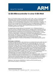
a. Light-load V OUT ripple in power-save mode. b. V OUT ripple in forced-<strong>PWM</strong> mode.<br />
Fig. 4. TPS62401 power-save (<strong>PFM</strong>) <strong>and</strong> fixed-frequency (<strong>PWM</strong>) operation waveforms.<br />
Topic 7<br />
Fig. 4a shows the increased output-voltage<br />
ripple <strong>and</strong> periodic switching cycles that occur in<br />
the power-save mode at light loads; it also shows<br />
the slightly higher output-voltage setpoint. Fig. 4b<br />
shows the reduced ripple voltage <strong>and</strong> continuous<br />
switching cycles that occur when the converter is<br />
operated in the forced-<strong>PWM</strong> mode.<br />
An additional enhancement that can be<br />
implemented to balance the trade-<strong>of</strong>f between<br />
good transient response (best in <strong>PWM</strong> mode) <strong>and</strong><br />
low power consumption (best in powersave/L<strong>PFM</strong><br />
mode) is an intermediate or F<strong>PFM</strong><br />
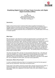
mode as shown for the TPS62350 in Fig. 5. The<br />
user can control the mode <strong>of</strong> operation using I 2 C<br />
comm<strong>and</strong>s to the converter IC. The device will<br />
automatically transition between either the L<strong>PFM</strong><br />
or the F<strong>PFM</strong> power-save mode (based on its<br />
preprogrammed register configuration) <strong>and</strong> the<br />
<strong>PWM</strong> mode as required by the load-current level.<br />
The L<strong>PFM</strong> mode works well for a system that<br />
goes from a high load to a very light load, as in<br />
sleep-mode operation. The L<strong>PFM</strong> control scheme<br />
is based on a fixed inductor peak current. To get a<br />
proper automatic transition between L<strong>PFM</strong> <strong>and</strong><br />
<strong>PWM</strong> operation, the inductor peak current is set<br />
higher than the <strong>PWM</strong> peak-to-peak ripple current.<br />
During the pulse-skipping phase, the converter runs<br />
only its internal reference <strong>and</strong> a comparator to<br />
monitor the output voltage. The advantage <strong>of</strong> L<strong>PFM</strong><br />
is much lower quiescent current <strong>and</strong> higher efficiency<br />
compared with F<strong>PFM</strong> at low output loads.<br />
If appropriately configured, the TPS62350<br />
will automatically transition from <strong>PWM</strong> mode<br />
into F<strong>PFM</strong> mode when the following conditions<br />
are met simultaneously for three or more clock<br />
cycles:<br />
• The output voltage is within its regulation<br />
limits.<br />
• The inductor valley current reaches zero.<br />
Efficiency – %<br />
100<br />
90<br />
80<br />
70<br />
60<br />
50<br />
40<br />
30<br />
20<br />
10<br />
L<strong>PFM</strong>/<strong>PWM</strong><br />
F<strong>PFM</strong>/<strong>PWM</strong><br />
3-MHz <strong>PWM</strong><br />
V I = 3.6 V<br />
V O = 1.5 V<br />
L = 1 µH<br />
C O = 10 µF<br />
0<br />
0.1 1 10 100 1000<br />
I O – Output Current – mA<br />
Fig. 5. L<strong>PFM</strong>, F<strong>PFM</strong>, <strong>and</strong> fixed-frequency <strong>PWM</strong><br />
efficiency <strong>of</strong> TPS62350.