

Anti-condensation valve - Caleffi
Anti-condensation valve - Caleffi
Anti-condensation valve - Caleffi

You also want an ePaper? Increase the reach of your titles
YUMPU automatically turns print PDFs into web optimized ePapers that Google loves.
<strong>Anti</strong>-<strong>condensation</strong> <strong>valve</strong><br />
280 series<br />
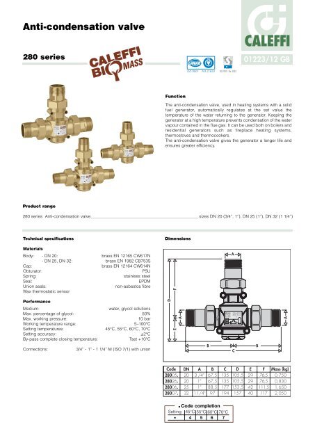
Product range<br />
Function<br />
CALEFFI<br />
01223/12 GB<br />
The anti-<strong>condensation</strong> <strong>valve</strong>, used in heating systems with a solid<br />
fuel generator, automatically regulates at the set value the<br />
temperature of the water returning to the generator. Keeping the<br />
generator at a high temperature prevents <strong>condensation</strong> of the water<br />
vapour contained in the flue gas. It can be used both on boilers and<br />
residential generators such as fireplace heating systems,<br />
thermostoves and thermocookers.<br />
The anti-<strong>condensation</strong> <strong>valve</strong> gives the generator a longer life and<br />
ensures greater efficiency.<br />
280 series <strong>Anti</strong>-<strong>condensation</strong> <strong>valve</strong> sizes DN 20 (3/4”, 1”), DN 25 (1”), DN 32 (1 1/4”)<br />
Technical specifications<br />
Materials<br />
Body: - DN 20: brass EN 12165 CW617N<br />
- DN 25, DN 32: brass EN 1982 CB753S<br />
Cap: brass EN 12164 CW614N<br />
Obturator: PSU<br />
Spring: stainless steel<br />
Seal: EPDM<br />
Union seals:<br />
Wax thermostatic sensor<br />
non-asbestos fibre<br />
Performance<br />
Medium: water, glycol solutions<br />
Max. percentage of glycol: 50%<br />
Max. working pressure: 10 bar<br />
Working temperature range: 5–100°C<br />
Setting temperatures: 45°C, 55°C, 60°C, 70°C<br />
Setting accuracy: ±2°C<br />
By-pass complete closing temperature: Tset +10°C<br />
Connections: 3/4” - 1” - 1 1/4” M (ISO 7/1) with union<br />
Dimensions<br />
ACCREDITED<br />
ISO 9001 FM 21654<br />
ISO 9001 No. 0003<br />
Code Mass (kg)<br />
● Code completion<br />
Setting 45°C 55°C 60°C 70°C<br />
● 4 5 6 7
Wooden biomass and <strong>condensation</strong> build-up<br />
Wooden solid fuel contains a variable moisture percentage<br />
depending on the type (logs, pellets, woodchips etc.) and<br />
seasoning. Water vapour is released during the solid fuel drying<br />
phase inside the combustion chamber. The presence of cold zones<br />
in the generator or flue gas chimney can lower the temperature of<br />
the flue gas down to the dew point, causing <strong>condensation</strong> to occur.<br />
Water vapour condenses on the generator surfaces, together with<br />
soot and part of the unburnt hydrocarbons contained in the flue<br />
gas, producing deposits and tar. These substances stick to the<br />
walls of the generator, covering most of the inner surfaces. In<br />
addition to being dangerous due to its flammability, tar is damaging<br />
to the integrity of the generator and limits the efficiency of the flue<br />
gas-system water exchanger.<br />
By keeping the generator walls at the highest possible temperature,<br />
the anti-<strong>condensation</strong> <strong>valve</strong> limits the formation of these<br />
substances, thereby increasing the combustion efficiency,<br />
controlling the emissions into the environment and prolonging the<br />
generator life.<br />
Flue gas and<br />
emission<br />
control<br />
Accumulation of ash<br />
and residues<br />
Primary and<br />
secondary air:<br />
Combustion<br />
efficiency<br />
SF<br />
SR<br />
ANTI-CONDENSATION<br />
VALVE<br />
Zone of <strong>condensation</strong><br />
forming:<br />
Deposits and tar<br />
Corrosion<br />
Reduction in heat<br />
exchanger efficiency<br />
Flammability<br />
Tf ≤ Tset SYSTEM START UP TRANSIENT<br />
by-pass open<br />
system return closed<br />
Tf ≤ Tset, Tmix=Tf<br />
SOLID<br />
FUEL<br />
GENERATOR<br />
Tmix = Tset + 10°C BY-PASS CLOSING<br />
by-pass closed<br />
system return open<br />
Tf > Tmix = Tset +10°C, Tmix=Tr<br />
SOLID<br />
FUEL<br />
GENERATOR<br />
Tf = Flow temperature<br />
Tset = <strong>Anti</strong>-<strong>condensation</strong> setting temperature<br />
Tf<br />
Tf<br />
1<br />
Characteristic components<br />
Return<br />
to generator<br />
1) Thermostatic sensor<br />
2) Obturator<br />
3) Spring<br />
Operating principle<br />
Flow<br />
by-pass<br />
System<br />
return<br />
4) Cap<br />
5) Valve body<br />
6) Temperature gauge holders<br />
The thermostatic sensor , completely immersed in the medium,<br />
controls the movement of an obturator that regulates the flows<br />
in by-pass and toward the system. At the start-up of the heat<br />
generator, the anti-<strong>condensation</strong> <strong>valve</strong> recirculates the flow water<br />
so as to bring the generator up to temperature as quickly as<br />
possible (fig. 1). When the flow temperature Tf exceeds the setting<br />
of the anti-<strong>condensation</strong> <strong>valve</strong> Tset, the <strong>valve</strong>’s cold port starts<br />
opening to produce the water mixing Tmix: in this phase the system<br />
loading begins (fig. 2).<br />
When the return temperature to the generator Tmix is greater than<br />
the setting of the anti-<strong>condensation</strong> <strong>valve</strong> by approximately 10°C,<br />
the by-pass port closes and water returns to the generator at<br />
the same temperature as the system return (fig. 3 and fig. 4).<br />
Tf > Tset START OF SYSTEM LOADING<br />
by-pass open<br />
system return open<br />
Tf > Tset, Tr < Tset, Tmix=Tset<br />
SOLID<br />
FUEL<br />
GENERATOR<br />
3 Tmix > Tset + 10°C SYSTEM LOADED<br />
by-pass closed<br />
system return open<br />
Tf > Tmix > Tset +10°C, Tmix=Tr<br />
4<br />
SOLID<br />
FUEL<br />
GENERATOR<br />
Tmix = Mixed water temperature of generator return<br />
Tr = System return temperature<br />
Tf<br />
Tf<br />
2
Construction details<br />
Brass body<br />
The brass body prevents the formation of ferrous residues in the<br />
system, thereby helping to prolong the life of the heat generator.<br />
Thermostatic sensor replacement for setting modification<br />
The thermostatic sensor can be easily<br />
removed for maintenance or setting<br />
change.<br />
Temperature gauge holders<br />
The body of the anti-<strong>condensation</strong> <strong>valve</strong><br />
in sizes DN 25 and DN 32 features<br />
temperature gauge holders on the front<br />
and rear sides. The holders allow the<br />
housing of code F29571 temperature<br />
gauges for controlling the working<br />
temperatures of the <strong>valve</strong>: by-pass water<br />
from the flow line, water returning from<br />
the system and mixed water returning to<br />
the generator.<br />
Hydraulic characteristics<br />
Size<br />
Connections<br />
Kv (m 3 /h)<br />
DN 20<br />
3/4”<br />
3,2<br />
Application diagram<br />
DN 20<br />
1”<br />
3,2<br />
DN 25<br />
1”<br />
9<br />
DN 32<br />
1 1/4”<br />
12<br />
Solid fuel generator, direct supply to the system.<br />
Safety devices to choose according<br />
to current regulations<br />
RESIDENTIAL<br />
DEVICE<br />
(m w.g.)<br />
Flow rate<br />
(l/min) (m3 /h)<br />
Sizing method / Setting selection<br />
According to the power output and thermal load on the heat<br />
generator, the flow rate provided by the generator can be<br />
calculated. With this value, it’s possible to use the hydraulic<br />
characteristics diagram to obtain the head loss of the <strong>valve</strong>. The<br />
size is selected by evaluating the compatibility of the obtained<br />
head loss value with the available head of the system pump. The<br />
setting (°C) must be selected so as to guarantee a return<br />
temperature to the generator that is high enough to prevent<br />
<strong>condensation</strong>, also using the information or instructions supplied by<br />
manufacturers of solid fuel generators.<br />
Installation<br />
The <strong>valve</strong> can be fitted on both sides of the generator in any<br />
position, vertical or horizontal. Installation is recommended on<br />
the return to the generator in mixing mode; it is also allowed on<br />
the flow from the generator in diverter mode according to the needs<br />
of system control.<br />
Installation in mixing mode (anti-<strong>condensation</strong>)<br />
SOLID<br />
FUEL<br />
GENERATOR<br />
Installation in diverter mode (system control)<br />
SOLID<br />
FUEL<br />
GENERATOR<br />
Deaerator<br />
Dirt separator<br />
Pump<br />
Shut-off <strong>valve</strong><br />
Expansion vessel<br />
Check <strong>valve</strong><br />
Motorised mixing <strong>valve</strong><br />
Pressure reducing <strong>valve</strong><br />
Filling unit<br />
Backflow preventer<br />
Safety relief <strong>valve</strong><br />
Dirt separator for vertical pipes<br />
Deaerator for vertical pipes<br />
Hydraulic separator<br />
Y-strainer
System with inertial storage<br />
Safety devices to choose according<br />
to current regulations<br />
SOLID<br />
FUEL<br />
GENERATOR<br />
Solid fuel generator, connection to inertial water storage in parallel.<br />
Safety devices to choose according<br />
to current regulations<br />
SOLID<br />
FUEL<br />
GENERATOR<br />
SPECIFICATION SUMMARY<br />
M M<br />
280 series<br />
<strong>Anti</strong>-<strong>condensation</strong> <strong>valve</strong>. Size DN 20 (from DN 20 to DN 32). Connections 3/4” (from 3/4” to 1 1/4”) M (ISO 7/1) with union.<br />
Brass body. Brass cap. PSU obturator. Stainless steel spring. EPDM seal. Wax thermostatic sensor. Medium water and glycol<br />
solutions. Maximum percentage of glycol 50%. Maximum working pressure 10 bar. Working temperature range 5–100°C.<br />
Setting temperatures 45°C, 55°C, 60°C, 70°C. Setting accuracy ±2°C. By-pass complete closing temperature<br />
Tset + 10°C.<br />
We reserve the right to change our products and their relevant technical data, contained in this publication, at any time and without prior notice.<br />
<strong>Caleffi</strong> S.p.A.<br />
S.R. 229 n. 25 · 28010 Fontaneto d’Agogna (NO) · Italy<br />
Tel. +39 0322 8491 · Fax +39 0322 863723<br />
info@caleffi.com · www.caleffi.com<br />
© Copyright 2012 <strong>Caleffi</strong>


