2. Basic circuits: Manual controllers - Intra lighting
2. Basic circuits: Manual controllers - Intra lighting
2. Basic circuits: Manual controllers - Intra lighting

You also want an ePaper? Increase the reach of your titles
YUMPU automatically turns print PDFs into web optimized ePapers that Google loves.
<strong>2.</strong> <strong>Basic</strong> <strong>circuits</strong>:<br />
<strong>Manual</strong> <strong>controllers</strong><br />
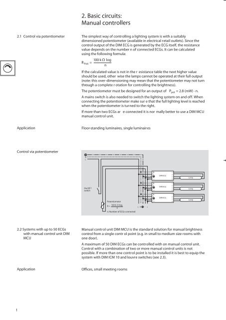
<strong>2.</strong>1 Control via potentiometer<br />
The simplest way of controlling a <strong>lighting</strong> system is with a suitably<br />
dimensioned potentiometer (available in electrical retail outlets). Since the<br />
control output of the DIM ECG is generated by the ECG itself, the resistance<br />
value depends on the number n of connected ECGs. It can be calculated<br />
using the following formula:<br />
100 k Ω log<br />
R Poti =<br />
n<br />
If the calculated value is not in the r esistance table the next higher value<br />
should be used, other wise the lamps cannot be operated at their full output<br />
(note: this over-dimensioning may mean that the potentiometer may not turn<br />
through a complete r otation for controlling the brightness).<br />
The potentiometer must be designed for an output of P pot = <strong>2.</strong>8 (mW) · n.<br />
A mains switch is also needed to switch the <strong>lighting</strong> system on and off. When<br />
connecting the potentiometer make sur e that the full <strong>lighting</strong> level is reached<br />
when the potentiometer is turned to the right.<br />
If more than two ECGs ar e connected it is nor mally better to use a DIM MCU<br />
manual control unit.<br />
Application<br />
Floor-standing luminaires, single luminair es<br />
Control via potentiometer<br />
N<br />
L<br />
1<br />
–<br />
+<br />
DIM ECG<br />
2<br />
3<br />
4<br />
Lamp<br />
On/Of f<br />
switch<br />
N<br />
L<br />
N<br />
L<br />
–<br />
+<br />
DIM ECG<br />
1<br />
2<br />
3<br />
4<br />
Lamp<br />
Potentiometer<br />
R =<br />
100 k Ω log.<br />
n<br />
n: Number of ECGs connected<br />
L N – +<br />
N<br />
1<br />
L<br />
2<br />
DIM ECG<br />
3<br />
–<br />
+ 4<br />
Lamp<br />
<strong>2.</strong>2 Systems with up to 50 ECGs<br />
with manual control unit DIM<br />
MCU<br />
<strong>Manual</strong> control unit DIM MCU is the standard solution for manual brightness<br />
control from a single contr ol point (e.g. in small to medium size rooms with<br />
one door).<br />
A maximum of 50 DIM ECGs can be controlled with on manual control unit.<br />
Control with a combination of two or more manual control units is not<br />
possible. If more than one control point is to be installed it is best to equip the<br />
system with DIM ICM 10 and louvre switches (see <strong>2.</strong>3).<br />
Application<br />
Offices, small meeting rooms<br />
1
Switching on/offf<br />
There is a pushbutton integrated in the manual control unit (electrically<br />
isolated from the brightness control). This switching contact is used to<br />
actuate r elays to switch ECGs together in different <strong>circuits</strong> or on different<br />
mains phases. A maximum of 10 single-lamp or 5 two-lamp dimmable<br />
ECGs can be switched directly in a circuit.<br />
Wiring diagram for systems<br />
with a maximum of 10 singlelamp<br />
dimmable ECGs or 5 twolamp<br />
dimmable ECGs<br />
N<br />
L<br />
1<br />
–<br />
+<br />
DIM ECG<br />
2<br />
3<br />
4<br />
Lamp<br />
– +<br />
<strong>Manual</strong> Control Unit<br />
DIM MCU<br />
L N – +<br />
N<br />
L<br />
N<br />
L<br />
–<br />
+<br />
DIM ECG<br />
N<br />
L<br />
DIM ECG<br />
1<br />
2<br />
–<br />
+<br />
3<br />
4<br />
1<br />
2<br />
3<br />
4<br />
Lamp<br />
Lamp<br />
Wiring diagram for systems<br />
with a maximum of 50 dimmable<br />
ECGs<br />
N<br />
L 3<br />
L 2<br />
L 1<br />
N<br />
L<br />
Relais<br />
N<br />
L<br />
–<br />
+<br />
DIM ECG<br />
1<br />
2<br />
3<br />
4<br />
Lamp<br />
– +<br />
<strong>Manual</strong> Contr<br />
DIM MCU<br />
ol Unit<br />
L 1 L 2 L 3<br />
N – +<br />
}<br />
N<br />
L<br />
–<br />
+<br />
DIM ECG<br />
N<br />
L<br />
DIM ECG<br />
1<br />
2<br />
–<br />
+<br />
3<br />
4<br />
1<br />
2<br />
3<br />
4<br />
Lamp<br />
Lamp<br />
Max. 50 DIM ECG<br />
For systems with mor e than 50 dimmable ECGs see 4.7<br />
Installation<br />
The manual control unit is suitable for installation in flush-type boxes with a<br />
diameter of 55/60 mm. There are two versions available. DIM MCU P is<br />
supplied with a rotary button and cover plate, wher eas DIM MCU has neither<br />
of these. In this case, the button and cover plate should be pur chased<br />
separately from the Berker , Gira or Jung range.<br />
Please note:<br />
The manual control unit may be destroyed if incorrectly installed.<br />
A separate supply voltage is not required for the manual control unit.<br />
Setting the minimum brightness<br />
Once the system has been installed, switch off all <strong>lighting</strong>, turn the button on<br />
the manual control unit to the left as far as it will go and adjust the trimmer<br />
until you can see light.<br />
2
71<br />
80<br />
Trim potentiometer<br />
for setting<br />
the minimal<br />
brightness<br />
Sicherung<br />
71<br />
80<br />
4<br />
33<br />
33<br />
51<br />
60<br />
54<br />
DIM MCU<br />
54<br />
DIM MCU P<br />
Technical data for manual control units DIM MCU<br />
Reference:<br />
DIM MCU or DIM MCU P<br />
Dimensions:<br />
for flush-type box Ø = 55/60 mm (see dimensional diagram)<br />
Rotar y axis: Ø = 4mm, l =14 mm and 6 mm thr ead<br />
Type of fixing:<br />
Claws or screws<br />
Permissible ambient temperature – 20 °C to + 50 °C<br />
Terminals:<br />
Scr ew terminals<br />
Permissible wire cr oss-section: max. 1.5 mm 2<br />
Terminal –:<br />
– (control signal)<br />
Terminal +:<br />
+ (control signal)<br />
Terminal and<br />
Switching contact 230V mains voltage<br />
Mains connection:<br />
Not required<br />
Effects of incor rect wiring<br />
230V at contr ol terminal:<br />
Fuse defective or total failur e<br />
Reversing +/–:<br />
always minimum luminous flux<br />
Control signal range:<br />
1 to 10V DC (voltage source in dimmable ECG)<br />
Load capacity of the manual contr ol Maximum of 40 mA or a maximum of 50 dimmable ECG<br />
unit for brightness control:<br />
or 16 signal amplifiers DIM SA<br />
Switching contact:<br />
250 V/6 A (10 single-lamp or<br />
5 two-lamp dimmable ECGs)<br />
Fuse:<br />
Fine fuse F500/H250<br />
Cover and r otary button: From the Berker (2891), Gira (30900)<br />
or Jung (240-10) range, as appropriate<br />
Note: Control with a combination of two or more manual control units is not<br />
possible.<br />
3