

NAVO 2 Function Decoder $29.95 - NCE
NAVO 2 Function Decoder $29.95 - NCE
NAVO 2 Function Decoder $29.95 - NCE

Create successful ePaper yourself
Turn your PDF publications into a flip-book with our unique Google optimized e-Paper software.
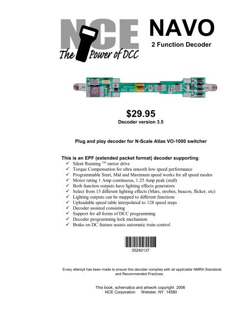
<strong>NAVO</strong><br />
2 <strong>Function</strong> <strong>Decoder</strong><br />
<strong>$29.95</strong><br />
<strong>Decoder</strong> version 3.5<br />
Plug and play decoder for N-Scale Atlas VO-1000 switcher<br />
This is an EPF (extended packet format) decoder supporting:<br />
Silent Running TM motor drive<br />
Torque Compensation for ultra smooth low speed performance<br />
Programmable Start, Mid and Maximum speed works for all speed modes<br />
Motor rating 1 Amp continuous, 1.25 Amp peak (stall)<br />
Both function outputs have lighting effects generators<br />
Select from 15 different lighting effects (Mars, strobes, beacon, flicker, etc)<br />
Lighting outputs can be mapped to different functions<br />
Uploadable speed table interpolated to 128 speed steps<br />
<strong>Decoder</strong> assisted consisting<br />
Support for all forms of DCC programming<br />
<strong>Decoder</strong> programming lock mechanism<br />
Brake on DC feature assists automatic train control<br />
05240137<br />
05240137<br />
Every attempt has been made to ensure this decoder complies with all applicable NMRA Standards<br />
and Recommended Practices.<br />
This book, schematics and artwork copyright 2006<br />
<strong>NCE</strong> Corporation Webster, NY 14580
<strong>Decoder</strong> Installation:<br />
1. Remove the locomotive shell from<br />
Tap Loco<br />
the chassis.<br />
downward<br />
2. Remove the light shroud (if any) at<br />
on edge of<br />
the rear of the loco.<br />
table causing<br />
3. Remove the fuel tank if necessary chassis to drop<br />
to allow future separation of the out of body shell<br />
frame halves.<br />
4. Loosen and remove the two screws<br />
holding the frame halves together.<br />
5. Lay the frame in its right side as<br />
shown in the photo below. Remove<br />
the top frame half. Place the trucks<br />
aside.<br />
6. Remove the factory light board from the frame.<br />
TABLE<br />
Removing the<br />
body shell<br />
Make sure only the<br />
pilot hits the table<br />
edge<br />
7. Orient the decoder with the motor tabs aligned with their contact pads on the decoder<br />
bottom (see photo below)<br />
8. Fit the decoder into the left frame half while ensuring that the motor tabs line up with their<br />
contact pads on the decoder bottom. Tweezers help here.<br />
9. Do not remove the yellow Kapton tape wrapped around the middle of the decoder. This<br />
prevents short circuits to the frame.<br />
10. Ensure that the two round frame insulators are still in place at each end of the frame<br />
before you re-install the right frame half and trucks.<br />
11. Make sure you have everything aligned correctly and the trucks rotate freely, then install<br />
the two frame screws.<br />
12. Test run the locomotive (see below) before replacing the light shroud and body shell.<br />
Always test your decoder installation on a current limited programming track before<br />
trying it on full track power.<br />
We recommend that the first "full power" testing be done on regular DC. The decoders<br />
should be driven by a good quality smooth DC power unit. Power packs with pulse<br />
power systems such as "tracking control", etc. will give unpredictable operation. Analog<br />
operation is included in your <strong>NCE</strong> decoders so you will be able to run on conventional<br />
layouts without having to remove the decoder or rewire your locomotive.<br />
**Last revised: 23 June 2006 Page 2 <strong>NAVO</strong>
Fine tuning locomotive operation<br />
The factory settings normally provide good performance for most locomotives in HO-Scale. You<br />
may want to improve or fine tune performance by adjust the starting characteristics or top speed .<br />
There are 6 CVs that define:<br />
The voltage at which the motor starts<br />
How often and how hard the motor gets kicked a slow speeds to keep it turning smoothly.<br />
The maximum motor speed<br />
The mid speed range response characteristics or ‘speed curve’.<br />
Compensation for a motor that runs faster in one direction<br />
Torque compensation kick rate - CV116:<br />
How frequently the motor is ‘kicked’ at slow speed. . The smaller the number the more often the<br />
motor gets a brief voltage ‘kick’. A value of 1 applies kicks continuously. Most N locos work well<br />
with values of 2-4. Factory default is 0 (off). The maximum practical value is about 8.<br />
Torque compensation kick strength - CV117:<br />
How hard the motor is ‘kicked’ at slow speed. Typical adjustment is 4 to 25 The larger the number<br />
the more voltage is applied in each ‘kick’. The strength of these kicks fade out ratiometrically as<br />
speed is increased providing a smooth transition to normal motor operation. Factory default is 0<br />
(off), usable range 0-50.<br />
Start Voltage - CV2 (Vstart): We prefer using Operations Mode Programming (Program on the<br />
Main) to set the Torque Compensation (CV116/117) before setting CV2 so the locomotive is just<br />
able to maintain movement at speed step 1. CV2 can then be used to “trim” the starting voltage.<br />
Vmax - CV5: If your locomotive runs too fast you can use CV5 to lower its maximum speed.<br />
Setting CV5 to 255 uses the maximum possible voltage to run the motor when full speed is<br />
requested. Set CV5 to a smaller value to reduce the top speed. A value of 128 will yield<br />
approximately ½ full voltage to the motor at top speed. 192 will provide about ¾ full voltage. All<br />
speeds from the middle speed step to the maximum will be proportionally reduced (see diagram). If<br />
CV5 is set to 0 the decoder will use 255 for maximum speed. Always make sure CV5 is greater than<br />
CV6 to avoid erratic operation.<br />
Vmid - CV6: CV6 determines how the motor responds through its middle speed ranges to<br />
advancement of the throttle. If you set CV6 lower than half the maximum speed you’ll have smaller<br />
increases in motor speed through the lower speed ranges. Then, as you hit the upper speed ranges<br />
there will be larger increases between speed steps. In the diagram below you can see this best<br />
illustrated by the ‘customized’ line. If you set Vstart larger than 0 you’ll will most likely want to raise<br />
Vmid so a reasonable slope is maintained in the ‘speed curve’. If CV6 is set to 0 the decoder will<br />
use 127 as the value. If you use high values in CV117 you will want to increase CV6 by a<br />
proportional amount to keep a smooth acceleration curve.<br />
Reverse trim (also forward trim) - CV95:<br />
Values from 1-127 make decoder run faster in reverse than forward. 1 is one speed step faster in<br />
reverse, 2 is two steps faster, etc.<br />
Values from 129-255 make decoder run faster in forward than reverse. 129 is one speed step<br />
faster in forward, 130 is 2 speed steps faster, etc. 0 and 128 add nothing to either direction .<br />
255<br />
factory default<br />
192<br />
Vmax<br />
128<br />
064<br />
Voltage<br />
customized<br />
Vstart<br />
Vmid<br />
Motor 'Speed Curve'<br />
000<br />
1 32 64<br />
96<br />
128<br />
Speed steps<br />
**Last revised: 23 June 2006 Page 3 <strong>NAVO</strong>
Effects programming (and function mapping) examples<br />
Mars Light:<br />
What we want to do:<br />
Use output 2 (yellow wire) for a Mars light.<br />
It is to be on in the forward direction only<br />
How to do it:<br />
Set Output 2 is to be activated by F1, set CV35 to 2<br />
Make sure F0 no longer controls output 2, set CV34 to 0)<br />
Configure output 2 as a forward only Mars light. Set CV121 to 9. We get the value of 9 by<br />
using 8 (Mars Light) plus 1 (output operates only in forward direction)<br />
Rule 17 lighting:<br />
Rule 17 refers to how the locomotive engineer operates the locomotive headlights during the running<br />
of the train. The rule varies from road to road but generally requires the dimming of the headlight(s)<br />
when in a siding waiting to meet another train, passing through passenger stations o r moving within<br />
yard limits.<br />
What we want to do:<br />
Use output 1 for the Headlight<br />
The headlight is to be on bright in both directions of locomotive travel<br />
We also want to be able dim the headlight<br />
Use output 2 for the rear light. It is to come on in reverse, off in forward<br />
How to do it:<br />
Output 1 is already activated by F0 (factory default setting of CV33 =1).<br />
Configure output 1 as a standard output, on in both directions, yet dimmable when F4 is<br />
activated. Set CV120 to 32 (20 hex). You can optionally set CV120 to 36 is you want F8 to<br />
control the dimming instead of F4.<br />
Configure the rear light to be on in reverse and off in forward operation: Set CV121 to 2<br />
Switcher:<br />
What we want:<br />
Headlights that dim in the opposite direction that the locomotive is travelling<br />
Use output 1 as Headlight and output 2 as Rearlight<br />
How to do it:<br />
Outputs 1 and 2 are already activated by F0 due to the factory default settings.<br />
Configure output 1 as bright in forward dim in reverse . Set CV120 to 44 (2C hex)<br />
Configure output 2 as bright in reverse dim in forward . Set CV121 to 40 (28 hex)<br />
**Last revised: 23 June 2006 Page 4 <strong>NAVO</strong>
Description of EFX configuration CVs<br />
CV120 - Lighting effect configuration for output 1 ( F0f ).<br />
CV121 - Lighting effect configuration for output 2 ( F0r ).<br />
Each output wire can select from 15 different lighting effects by using its associated EFX<br />
configuration CV. Pick the value for the CV from the table below, add 1 or 2 if you want<br />
the effect to be directional (footnotes 2 and 3), then add 128 if you are using a white LED<br />
for the effect. Ditch lights should not be made directional, they’re not dierectional in real<br />
life.<br />
bit weight<br />
128<br />
64<br />
32<br />
16<br />
8<br />
4<br />
2<br />
1<br />
bit name<br />
LED 1<br />
---<br />
Effect configuration<br />
REV 2<br />
FWD 3<br />
Value for<br />
CV<br />
0<br />
4<br />
8<br />
12<br />
16<br />
20<br />
24<br />
28<br />
32<br />
36<br />
40<br />
44<br />
48<br />
52<br />
56<br />
60<br />
Description of lighting effect<br />
Standard on/off function output<br />
Firebox flicker (brighter when accelerating)<br />
Mars light<br />
Rotary Beacon<br />
Gyralight<br />
Double Strobe<br />
Strobe A<br />
Strobe B (alternates with Strobe A)<br />
Dim when F0 and F4 on, otherwise bright<br />
Dim when F0 and F8 on, otherwise bright<br />
Dim in forward, bright in reverse<br />
Dim in reverse, bright in forward<br />
Type 2 Right Ditch light, effect on if F2 on, output<br />
off otherwise<br />
Type 2 Left Ditch light, effect on if F2 on, output<br />
off otherwise<br />
Type 1 Right Ditch light, effect on if F0 and F2<br />
on, bright if F0 on and F2 off, off if F0 off<br />
Type 1 Left Ditch light, effect if F2 and F0 on,<br />
bright if F0 on and F2 off, off if F0 off<br />
Hex (for<br />
Digitrax users)<br />
0<br />
4<br />
8<br />
0C<br />
10<br />
14<br />
18<br />
1C<br />
20<br />
24<br />
28<br />
2C<br />
30<br />
34<br />
38<br />
3C<br />
1 - <strong>Function</strong>s are designed to use 12-16 volt 30-40ma incandescent lamps. If you are using a<br />
white LED (with 1K limiting resistor) add 128 to the CV value.<br />
2 - If you want the function to be active only in the reverse direction add 2 to the CV value<br />
3 - If you want the function to be active only in the forward direction add 1 to the CV value<br />
**Last revised: 23 June 2006 Page 5 <strong>NAVO</strong>
Description of function mapping CVs:<br />
<strong>Function</strong> mapping can change which outputs are controlled by a function command from<br />
your handheld cab. It is possible to have one command control several outputs. In the<br />
table below each row corresponds to a function mapping CV and each column indicates<br />
an output number. The bold number in a column is the factory default. Programming the<br />
CV to the value under an output number will change that output to be controlled by that<br />
function number. In the table below the factory value of CV34 is 2 which means F0 will<br />
control Output #2. If you want F1 to control output 2 program CV35 to 2. If you want F1<br />
to control both outputs 1 and 2 add the two values for those outputs together (1+2=3) and<br />
program CV35 with 3.<br />
Note in this decoder CV33 and CV34 operate identically. They are not<br />
directional...directionality is provided in the EFX configuration CV for each output.<br />
Factory default function mapping values<br />
CV33 F0 Fwd<br />
CV34 F0 Rev<br />
CV35 F1<br />
CV36 F2<br />
CV37 F3<br />
OUTPUT<br />
NUMBER<br />
2<br />
2<br />
2<br />
2<br />
2<br />
2<br />
1<br />
1<br />
1<br />
1<br />
1<br />
1<br />
**Last revised: 23 June 2006 Page 6 <strong>NAVO</strong>
Factory default values for decoder Configuration Variables (Cvs)<br />
CV<br />
1<br />
2<br />
3<br />
4<br />
5<br />
6<br />
7<br />
11<br />
15<br />
16<br />
17<br />
18<br />
19<br />
21<br />
22<br />
23<br />
24<br />
29<br />
30<br />
33<br />
34<br />
35<br />
36<br />
37<br />
38<br />
39<br />
40<br />
41<br />
42<br />
67<br />
68<br />
Default value<br />
decimal hex<br />
3 03<br />
0 00<br />
0 00<br />
0 00<br />
0 00<br />
0 00<br />
35 23<br />
0 00<br />
0 00<br />
0 00<br />
192 C0<br />
0 00<br />
0 00<br />
255 FF<br />
63 3F<br />
0 00<br />
0 00<br />
6 06<br />
0 00<br />
1 01<br />
2 02<br />
4 04<br />
8 08<br />
16 10<br />
4 04<br />
8 08<br />
16 10<br />
0 0<br />
0 0<br />
0 0<br />
0 0<br />
Description<br />
short address<br />
start voltage<br />
acceleration<br />
deceleration<br />
maximum speed<br />
mid speed<br />
decoder version<br />
Packet timeout value<br />
Programming “key”<br />
Programming “lock”<br />
long address high byte<br />
long address low byte<br />
consist address<br />
consist functions F1-F8<br />
consist function FLF,FLR<br />
acceleration adjust<br />
deceleration adjust<br />
decoder configuration<br />
error/reset register<br />
Output(s) controlled by F0<br />
Output(s) controlled by F0<br />
Output(s) controlled by F1<br />
Output(s) controlled by F2<br />
Output(s) controlled by F3<br />
not used<br />
not used<br />
alt spd table step 1<br />
alt spd table step 2<br />
CV<br />
69<br />
70<br />
71<br />
72<br />
73<br />
74<br />
75<br />
76<br />
77<br />
78<br />
79<br />
80<br />
81<br />
82<br />
83<br />
84<br />
85<br />
86<br />
87<br />
88<br />
89<br />
90<br />
91<br />
92<br />
93<br />
94<br />
95<br />
116<br />
117<br />
118<br />
120<br />
121<br />
Default value<br />
decimal hex<br />
0 0<br />
0 0<br />
0 0<br />
0 0<br />
0 0<br />
0 0<br />
0 0<br />
0 0<br />
0 0<br />
0 0<br />
0 0<br />
0 0<br />
0 0<br />
0 0<br />
0 0<br />
0 0<br />
0 0<br />
0 0<br />
0 0<br />
0 0<br />
0 0<br />
0 0<br />
0 0<br />
0 0<br />
0 0<br />
0 0<br />
0 0<br />
0 0<br />
0 0<br />
20 14<br />
1 01<br />
2 02<br />
Description<br />
alt spd table step 3<br />
alt spd table step 4<br />
alt spd table step 5<br />
alt spd table step 6<br />
alt spd table step 7<br />
alt spd table step 8<br />
alt spd table step 9<br />
alt spd table step 10<br />
alt spd table step 11<br />
alt spd table step 12<br />
alt spd table step 13<br />
alt spd table step 14<br />
alt spd table step 15<br />
alt spd table step 16<br />
alt spd table step 17<br />
alt spd table step 18<br />
alt spd table step 19<br />
alt spd table step 20<br />
alt spd table step 21<br />
alt spd table step 22<br />
alt spd table step 23<br />
alt spd table step 24<br />
alt spd table step 25<br />
alt spd table step 26<br />
alt spd table step 27<br />
alt spd table step 28<br />
reverse trim<br />
torque kick rate<br />
torque kick strength<br />
ditch light hold time<br />
output 1 EFX generator<br />
output 2 EFX generator<br />
Configuration of CV29 settings:<br />
Table of commonly used values for CV29<br />
Value for CV29<br />
decimal hex<br />
0<br />
6<br />
18<br />
22<br />
34<br />
38<br />
50<br />
54<br />
2<br />
6<br />
12<br />
16<br />
22<br />
26<br />
32<br />
36<br />
Long/Short<br />
Address<br />
Short<br />
Short<br />
Short<br />
Short<br />
Long<br />
Long<br />
Long<br />
Long<br />
Uploadable/Facto<br />
ry Speed table<br />
Factory<br />
Factory<br />
Uploadable<br />
Uploadable<br />
Factory<br />
Factory<br />
Uploadable<br />
Uploadable<br />
Analog<br />
(DC)<br />
operation<br />
no<br />
yes<br />
no<br />
yes<br />
no<br />
yes<br />
no<br />
yes<br />
Speed mode<br />
28/128<br />
28/128<br />
28/128<br />
28/128<br />
28/128<br />
28/128<br />
28/128<br />
28/128<br />
Hex numbers are provided for early Digitrax users<br />
Notes:<br />
If you want to reverse the direction of travel on DCC increase the value for CV29 by one (this<br />
also reverses all directional lighting).<br />
If you want to reverse the DC direction reverse the track pickup wires.<br />
**Last revised: 23 June 2006 Page 7 <strong>NAVO</strong>
Configuration Variables used by V3.5 <strong>Decoder</strong>s<br />
CV1 Short decoder address; 1-127 valid<br />
CV2 Start Voltage (useful range 0-100)<br />
CV3 Acceleration rate (each unit = 7mS between speed steps) 255 max.<br />
CV4 Deceleration rate (each unit = 7mS between speed steps) 255 max.<br />
CV5 Vmax, speed at highest speed step. 0=use factory default of 255<br />
CV6 Vmid, speed (on a scale of 1-255) at speed step 7,14,or 63. 0=use default of 127<br />
CV7 <strong>Decoder</strong> version number. This decoder is 35 which means version 3.5<br />
CV8 Manufactuer ID. <strong>NCE</strong> = 11 (0B hex)<br />
CV11 Packet timeout value (in ½ second increments) Time the decoder will wait before braking to a<br />
stop after running into a section of track with DC power. 0=Don’t brake<br />
CV15 <strong>Decoder</strong> programming lock “KEY”. This CV is always programmable even when “locked”<br />
CV16 <strong>Decoder</strong> programming lock ID. When CV15=CV16, programming is unlocked and the<br />
decoder will respond to programming commands. If CV15 is not equal to CV16 then<br />
decoder programming is locked and it will not program (except CV15) or read.<br />
CV17 High byte of long (4 digit) address<br />
- bit 6,7 always= 1<br />
- bits 0-5 are upper 6 bits of address<br />
CV18 Low byte of long (4 digit) address<br />
CV19 Consist address. (0 or 128 = no consist active)<br />
- bits 0-6 short consist address (1-127 valid)<br />
- bit 7 0= direction is normal, 1= direction is reversed<br />
CV21 <strong>Function</strong>s active in consist mode. Bit 0 controls F1,bit 1=F2, bit 2=F3, etc.<br />
- bit 0 - 1=function can be controlled at consist address, 0 = no consist control<br />
CV22 <strong>Function</strong>s active in consist mode. Bits 0,1 control FLF and FLR respectively<br />
each bit 1=function can be controlled at consist address, 0 = no consist control<br />
CV29 - bit 0 1= direction of operation is reversed, 0= direction is normal<br />
- bit 1 1=28 speed mode (always enabled)<br />
- bit 2 1= analog operation mode enabled, 0 = disabled<br />
- bit 4 1= alternate speed table active, 0= use table defined by CV2,5,6<br />
- bit 5 1= use long address in CV17/18, 0= use short address CV1<br />
- bits 3,6,7 are ignored by the decoder<br />
CV30 Set this CV to 2 on the programming track and the decoder will reset to factory settings.<br />
CV33-CV37 function mapping CVs for F0-F3<br />
CV67-CV94 Uploadable speed table steps 1-28 (128 speed mode calculates intermediate steps)<br />
CV95 Reverse trim, values 1-127 add to reverse speed, values 129-255 add to forward speed<br />
CV116 Torque kick rate - number of 16ms periods in a row that motor is ‘kicked’ with voltage pulse<br />
CV117 Torque kick strength - how much voltage is used to kick the motor at slow speeds. Reduces<br />
to 0 as speed is increased.<br />
CV118 Ditch light hold time (in ¼ second increments) after F2 goes off.<br />
CV120-CV121 Effects configuration registers for outputs 1 and 2<br />
CV NOTES: All CV numbers not listed above may be programmed but not used by the decoder. This<br />
decoder supports all DCC programming methods.<br />
Formula for computing the long address if using a Lenz SET01 or SET02:<br />
If using a Lenz SET01, SET02, SET90, SET100 or other entry level system, use paged programming<br />
mode and see below for programming long addresses.<br />
CV17 = 192 + (the whole number portion of the long address divided by 256)<br />
CV18 = the remainder after the long address is divided by 256<br />
CV29 = 34 if analog mode disabled, 38 if analog mode enabled<br />
<strong>Decoder</strong> Warranty<br />
This decoder is fully factory tested and warranted against manufacturing defects for a period of 1 year. As the<br />
circumstances under which this decoder is installed can not be controlled, failure of the decoder due to installation<br />
problems can not be warranted. This includes misuse, miswiring, operation under loads beyond the design range of<br />
the decoder or short ciruits in the locomotive manufacturer’s factory wiring. If the decoder fails for non-warranted<br />
reasons <strong>NCE</strong> will replace the decoder, no questions asked, for $10 U.S. plus $2 shipping. For warranty or<br />
non-warranty replacement send the decoder (and any payment, if required) to:<br />
<strong>NCE</strong> Warranty Center<br />
899 Ridge Road<br />
Webster, New York 14580<br />
05240137<br />
05240137<br />
The terms Silent Running, Powerhouse Pro, Power Pro, SmartCab, ProCab, Switch-It, Snap-It, the <strong>NCE</strong> logo with “Power of DCC”<br />
slogan and EFX are trademarks of <strong>NCE</strong> Corporation. Digitrax is a trademark of Digitrax Inc.<br />
**Last revised: 23 June 2006 Page 8 <strong>NAVO</strong>


