Driving a character type LCD from a PC printer port - Hantronix, Inc
Driving a character type LCD from a PC printer port - Hantronix, Inc
Driving a character type LCD from a PC printer port - Hantronix, Inc

You also want an ePaper? Increase the reach of your titles
YUMPU automatically turns print PDFs into web optimized ePapers that Google loves.
Application Note<br />
Crystal Clear and Visibly Superior <strong>LCD</strong> Modules<br />
<strong>Driving</strong> a<strong>character</strong> <strong>type</strong> <strong>LCD</strong> <strong>from</strong> a<strong>PC</strong> <strong>printer</strong> <strong>port</strong><br />
General:<br />
Character(alphanumeric)<strong>type</strong><strong>LCD</strong>modules are most commonlydriven<strong>from</strong>anembeddedmicrocontroller. It<br />
is sometimes desirabletobeabletodrivethis <strong>type</strong>of moduledirectly <strong>from</strong> a<strong>PC</strong>. This wouldallowthemodule<br />
tobetestedorademonstration orsimulationtobeset upquicklyandwithaminimum of engineering. This<br />
applicationnotedescribesamethodof drivingan<strong>LCD</strong><strong>character</strong>module<strong>from</strong>the <strong>printer</strong><strong>port</strong> of a<strong>PC</strong>with<br />
minimalexternalhardware.<br />
The <strong>printer</strong> <strong>port</strong> of a<strong>PC</strong>:<br />
Thereareat least three versions of <strong>printer</strong><strong>port</strong>savailablenowon <strong>PC</strong>s.<br />
! SPP (StandardParallel Port)<br />
! EPP (EnhancedParallel Port)<br />
! ECP (Extended Capability Port)<br />
Tomakethis designasuniversal as possible itwill bebasedontheleast capableandoldest specification,<br />
SPP.<br />
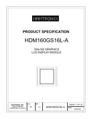
S4 S5 S7 S6<br />
D7 D6 D5 D4 D3 D2 D1 D0 C0<br />
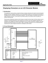
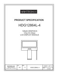
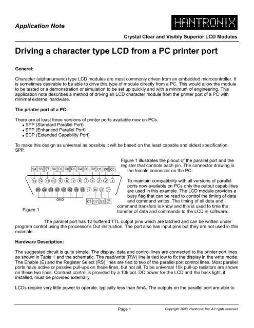
Figure1illustrates thepinoutof theparallel<strong>port</strong> andthe<br />
registerthat controls eachpin. Theconnectordrawingis<br />
thefemaleconnectoronthe<strong>PC</strong>.<br />
Figure1<br />
13 12 11 10 9 8 7 6 5 4 3 2 1<br />
25 24 23 22 21 20 19 18 17 16 15 14<br />
GND<br />
C3 C2 S3 C1<br />
Tomaintain compatibility withallversions of parallel<br />
<strong>port</strong>snowavailable on<strong>PC</strong>s onlytheoutput capabilities<br />
are used inthis example. The<strong>LCD</strong>moduleprovidesa<br />
busy flagthat canbereadto control thetimingof data<br />
andcommand writes. Thetiming of alldataand<br />
commandtransfers is knowandthis is usedtotimethe<br />
transferof dataandcommands tothe <strong>LCD</strong>insoftware.<br />
Theparallel <strong>port</strong> has 12bufferedTTLoutput pins which arelatchedandcanbewrittenunder<br />
program control usingtheprocessor’s Out instruction. The <strong>port</strong>alsohas input pins but they arenotusedin this<br />
example.<br />
Hardware Description:<br />
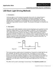
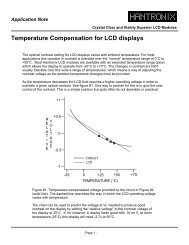
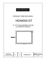
Thesuggestedcircuit is quitesimple. Thedisplay,dataandcontrollines areconnectedtothe<strong>printer</strong><strong>port</strong> lines<br />
as showninTable 1andtheschematic.Theread/write(RW)lineis tiedlowtofixthedisplayin thewrite mode.<br />
TheEnable (E)andtheRegisterSelect (RS)lines are tiedtotwoof theparallel<strong>port</strong> controllines. Mostparallel<br />
<strong>port</strong>s haveactiveorpassivepull-ups ontheselines, butnot all.Tobeuniversal 10k pull-upresistors areshown<br />
onthesetwolines. Contrast controlis provided bya10k pot. DCpowerforthe<strong>LCD</strong>and theback light,if<br />
installed, must beprovidedexternally.<br />
<strong>LCD</strong>s requirevery littlepowertooperate, typically less than5mA. The outputs ontheparallel<strong>port</strong>areableto<br />
Page1<br />
Copyright 2000, <strong>Hantronix</strong>,<strong>Inc</strong>.Allrights reserved
Application Note<br />
Crystal Clear and Visibly Superior <strong>LCD</strong> Modules<br />
sourceupto10mA, soitispossibletopowerthe<strong>LCD</strong><strong>from</strong> oneof theoutput lines. This doesn’t apply to the<br />
back light whichrequires <strong>from</strong> 50mA to300mA. Oneof thecontrollines canbeusedforthis purposeas shown<br />
C2 16<br />
Figure2<br />
1N4148<br />
+<br />
1uF<br />
V DD<br />
P<br />
A<br />
R<br />
A<br />
LL<br />
E<br />
L<br />
P<br />
O<br />
R<br />
T<br />
D0 2<br />
3<br />
4<br />
5<br />
6<br />
7<br />
8<br />
D7 9<br />
C0 1<br />
C3 17<br />
D0<br />
<strong>LCD</strong> Display Module<br />
D7 E RS R/W V SS<br />
V DD V DD<br />
10K<br />
10k 10k<br />
V L<br />
V DD<br />
V DD<br />
Schematic<br />
inFigure2. This alsohas theadvantageof being abletoshutoff thedisplay viasoftware. A1onthisline turns<br />
thedisplay onand a0turns it off.<br />
The<strong>type</strong> of cableusedtoconnectthe parallel <strong>port</strong> tothe<strong>LCD</strong>will determinethemaximumlengthofthe cable.<br />
Ribboncable, forinstance, shouldnot beusedinlengths over3’.Ashielded, twistedpaircablecanbeused<br />
upto50’. The quickest and most economical way ofbuildingashielded, twistedpairin smallquantities is to<br />
useacommercial <strong>printer</strong>cableof thedesiredlengthandcut offtheconnectorthatwould normallyconnect to<br />
the<strong>printer</strong>. The wiresarethenpreparedand connectedtothe<strong>LCD</strong>module.<br />
Software:<br />
Most contemporary <strong>PC</strong>s sup<strong>port</strong> 3parallel<strong>port</strong>s at addresses 278/378/3BC. All values areinhex. Usually only<br />
one <strong>port</strong>isphysically installed andinmostsystems it is at address 378 andis assignedtoLPT1. Anoutput<br />
instructiontothe base addressof the<strong>port</strong>,278/378/3BC, willlatchdatatothe data <strong>port</strong>of the<strong>LCD</strong>as shown<br />
below.<br />
BIT 7 6 5 4 3 2 1 0<br />
PIN 9 8 7 6 5 4 3 2<br />
<strong>LCD</strong> D7 D6 D5 D4 D3 D2 D1 D0<br />
Anoutputinstructiontothebaseaddress ofthe<strong>port</strong> +2, 27A/37A/3BE, willlatchthelower 4bits of thedata<br />
bus tothecontrolpins of the<strong>LCD</strong>. Onlytwoof thesesignals areneededtocontrolmost <strong>LCD</strong><strong>character</strong><br />
modules.Theexceptionis the40<strong>character</strong>by4linemodules. Thesemodules havetwocontrollers onthem<br />
and havean extraenableline.The<strong>port</strong> pinC1canbeusedforthis 2ndenableonthe40x4modules.Thebits<br />
areassigned tothe<strong>LCD</strong>as shownbelow.<br />
BIT 7 6 5 4 3 2 1 0<br />
PIN - - - - 17 16 14 1<br />
<strong>LCD</strong> RS E2* E *=40x4modules only.<br />
Page2<br />
Copyright 2000, <strong>Hantronix</strong>,<strong>Inc</strong>.Allrights reserved
Application Note<br />
Crystal Clear and Visibly Superior <strong>LCD</strong> Modules<br />
Program Example:<br />
Thefollowingsample<br />
code is writteninMicrosoftCandwilldisplayamessageonatwolineby 16<strong>character</strong><br />
<strong>LCD</strong>module. It can beusedasaguide inworkingwithlargerorsmallermodules as it has allof theelements<br />
needed. Atotal of 80<strong>character</strong>s is writentothedisplay whichis themaximum any <strong>LCD</strong><strong>character</strong>display with<br />
one controllercan store. This program will thuswork fora1, 2or4linedisplay althoughonlytwolines will<br />
display <strong>character</strong>s ona4linemodule.<br />
Amoresophisticatedwayof writing <strong>character</strong>s is toissueaSETDDRAMADDRESS commandforeachline<br />
tobewritten. Check withthedatasheet fortheparticularmoduleyouareusingto set theDDRAM address<br />
and linelengths.<br />
Theprogram first initializes thedisplay andthensends thetwolines ofdata. Thedisplayedmessageshould<br />
read:<br />
>> HANTRONIX > HANTRONIX
Application Note<br />
Crystal Clear and Visibly Superior <strong>LCD</strong> Modules<br />
_out(CONTROL, _inp(CONTROL)|0x08); /*Set RS */<br />
/* Initializationroutine */<br />
for(count=0;count