MULTIPLEX SENSOR TELEMETRY
MULTIPLEX SENSOR TELEMETRY
MULTIPLEX SENSOR TELEMETRY

Create successful ePaper yourself
Turn your PDF publications into a flip-book with our unique Google optimized e-Paper software.
<strong>MULTIPLEX</strong><br />
<strong>SENSOR</strong> <strong>TELEMETRY</strong><br />
Q<br />
MANNER<br />
®<br />
MA<br />
Sensortelemetrie
<strong>SENSOR</strong> <strong>TELEMETRY</strong> –<br />
COMPACT AND CONSISTENT<br />
FOR TEST-STAND AND<br />
SERIES APPLICATIONS<br />
FROM ENGINEERING<br />
TO THE APPLICATION<br />
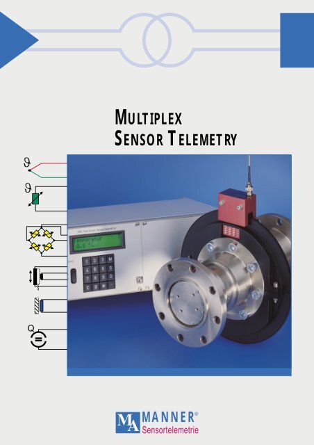
The MANNER multiplex system product<br />
family was developed especially for the<br />
non-contact (telemetric) transmission of<br />
measurement data on moving objects in<br />
mechanical engineering, particularly rotating<br />
shafts.<br />
The objective of sensor telemetry is to<br />
eliminate the usual problems involved<br />
with slip-rings, e.g. wear and tear, maintenance,<br />
signal interference and EMV instability.<br />
Furthermore, miniaturized sensor<br />
signal amplifiers and rotor electronics<br />
(8 channel 10 x 32 x 22 mm, 10 g) have<br />
made it possible to realize entirely new<br />
problem scenarios. Transmission via an<br />
interference-proof code guarantees the<br />
highest freedom from interference.<br />
■<br />
■<br />
■<br />
Digital transmission PCM<br />
(time division multiplex)<br />
FM transmission<br />
(time division multiplex)<br />
Antenna multiplex<br />
The product program from MANNER provides<br />
ready-made solutions for almost all<br />
areas of application, regardless of whether<br />
signals are sensed radially or axially. The<br />
consistently designed concept of sensor<br />
signal amplifiers and transmission elements<br />
(antenna) makes the telemetering system<br />
from MANNER particularly user-friendly.<br />
The extensive standard program – which also<br />
includes components of miniature design<br />
– provides flexibility for virtually all applications<br />
in sensor telemetry.<br />
Power supply for the transducer and the rotor<br />
electronics takes place inductively. No<br />
batteries are used.<br />
<strong>SENSOR</strong> <strong>TELEMETRY</strong> FOR<br />
STRESS ANALYSIS<br />
If the standard components for your measuring<br />
task need to be altered or are not<br />
even suitable, our engineering group is<br />
at your service to work out an application-specific<br />
solution. It will give you advice<br />
on the measuring task and make our<br />
extensive know-how about the entire<br />
spectrum of sensor telemetry available to<br />
you.<br />
■<br />
■<br />
■<br />
■<br />
■<br />
■<br />
■<br />
■<br />
Consultation<br />
Project planning<br />
Selection of optimal transducers<br />
DMS application<br />
Assistance during measurement<br />
Training in how to utilize the telemetry<br />
installation<br />
Implementation of complete measuring<br />
orders<br />
Manufacture and packaging of<br />
custom-built telemetry installations<br />
<strong>SENSOR</strong> <strong>TELEMETRY</strong> FOR<br />
VEHICLE MEASURING<br />
<strong>SENSOR</strong> <strong>TELEMETRY</strong><br />
FOR TEST APPLICATIONS<br />
2
THE AREAS OF APPLICATION<br />
THE MEASURABLE VARIABLES<br />
THE FEATURES<br />
Because of the modular program, sensor<br />
telemetry from MANNER is suitable for<br />
the most varied types of application:<br />
■<br />
■<br />
■<br />
■<br />
■<br />
■<br />
■<br />
■<br />
■<br />
■<br />
■<br />
■<br />
■<br />
laboratory measuring technology<br />
vehicle measuring technology<br />
construction machinery<br />
hoisting plants in mining<br />
gear and motor measuring technology<br />
test-stand technology<br />
helicopter rotors<br />
wind generators<br />
turboblowers<br />
process technology<br />
machine monitoring<br />
process monitoring<br />
slip-ring replacement<br />
<strong>SENSOR</strong> <strong>TELEMETRY</strong><br />
FOR TEST-STAND APPLICATIONS<br />
Typical physical measurable variables<br />
are:<br />
■<br />
■<br />
■<br />
■<br />
■<br />
■<br />
■<br />
■<br />
THE SYSTEM<br />
■<br />
■<br />
■<br />
■<br />
torque<br />
power<br />
strain<br />
acceleration<br />
linear or longitudinal deformation<br />
distance<br />
temperature<br />
pressure<br />
sensor signal amplifier<br />
(rotor electronics)<br />
evaluation unit (receiver)<br />
reception antenna pick-up<br />
rotor induction loop<br />
■<br />
■<br />
■<br />
■<br />
■<br />
■<br />
maintenance-free via inductive<br />
energy-coupling for sensor and<br />
sensor signal amplifier (no batteries)<br />
digital transmission (digitalization in<br />
rotor electronics, PCM), FM technology<br />
or antenna multiplex<br />
remote-controlled measuring range<br />
selection and automatic zero point<br />
line-up in rotor electronics (during<br />
measuring operation)<br />
very easy handling and assembly,<br />
with minimal space requirements<br />
high transmission accuracy (zero<br />
point drift 0.003% Centigrade)<br />
measuring signal bandwidth 0 - 10 kHz<br />
■ scanning rate up to 100,000<br />
samples/sec<br />
■<br />
remote-controlled metering point<br />
changeover switch<br />
■ high environmental stability (IP 67);<br />
high immunity to interference<br />
■<br />
ambient temperature from -30 °C to<br />
+125 °C (optionally to 150 °C)<br />
■<br />
for commercially available sensors<br />
■<br />
■<br />
any shaft diameter from 0 to 2,000 mm,<br />
no free shaft end necessary<br />
integrated engine speed measurement<br />
(optional)<br />
■<br />
integrated remote calibration function<br />
MANNER<br />
®<br />
MA<br />
Sensortelemetrie<br />
3
FOR USE EVEN IN THE<br />
TOUGHEST ENVIRONMENTS<br />
Application of telemetry depends to a great<br />
extent on environmental stability. The systems<br />
from MANNER have been specially<br />
developed for use in tough environments<br />
and are distinctive for the following characteristics:<br />
■ extremely sturdy (massive terminal pins)<br />
■ generally oil-proof<br />
■ supplied with protection type IP 67<br />
■ extremely resistant to acceleration<br />
(optionally up to 100,000 g)<br />
■ temperature-stable from -25 °C to +125 °C<br />
(optionally from -40 °C to +150 °C)<br />
■ minimal weight<br />
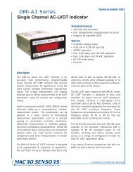
THE DECISIVE ADVANTAGE:<br />
IMMUNITY TO INTERFERENCE<br />
Drive shaft test-stand with water and<br />
silica-sand rinse<br />
The decisive advantage of MANNER<br />
Sensor Telemetry as opposed to slip<br />
rings lies in immunity to interference. The<br />
systems from MANNER can be utilized<br />
even when EMV load is high.<br />
Operation in close proximity to frequency<br />
converters is problem-free.<br />
Even installation of the system in GTOcontrolled<br />
large motors with 50 megawatt<br />
performance delivers interference-free<br />
signals (see photo, right).<br />
Rotor temperature monitoring on GTOcontrolled<br />
50-megawatt motor<br />
4
MINIATURE DESIGNS<br />
The units are of increasingly compact design.<br />
Component reserves are getting smaller<br />
all the time and verification of component<br />
load is becoming ever more important. The<br />
amount of space taken up by a measuring<br />
amplifier in the unit is usually very critical.<br />
Alterations in serial parts are often ruled out.<br />
The installability of rotor electronics depends<br />
to a great extent on their dimensions.<br />
The miniature designs from MANNER were<br />
developed especially for gear and motor applications.<br />
Despite their massive design they<br />
are extremely lightweight, need very little<br />
space for insertion, and can be used in ambient<br />
temperatures of up to +150 °C.<br />
Sensor telemetry on gear input shaft<br />
This product series functions according to<br />
the tried and tested FM modulation method<br />
with time division multiplex. The eight-channel<br />
module, for instance, measures only 22 x<br />
10 x 32 mm and weighs a mere 15 g.<br />
ADVANTAGES OVER SLIP-RING TRANSMITTERS<br />
■<br />
■<br />
■<br />
■<br />
high signal quality – no signal<br />
interruptions<br />
no wear and tear, bearing-free, no extra<br />
torque<br />
high EMV interference immunity via<br />
galvanic separation between rotor and<br />
stator<br />
high EMV security via amplification of the<br />
measuring signal in the rotor<br />
■<br />
integrated measuring amplifier<br />
■<br />
no constructional limitations with regard<br />
to mounting<br />
Sensor telemetry for vibration analysis on<br />
turboblower via DMS<br />
MANNER<br />
MA<br />
Sensortelemetrie<br />
®<br />
5
THE<br />
<strong>SENSOR</strong>S<br />
PIEZOELECTRIC<br />
<strong>SENSOR</strong>S<br />
THE IMPORTANCE<br />
OF ACCURACY<br />
The preamplifiers are already integrated into<br />
the rotor electronics. All the usual commercial<br />
sensors can be connected directly to<br />
the sensor signal amplifier, without the need<br />
for any extra amplifiers.<br />
The rotor electronics also ensure that the<br />
sensors are powered (no batteries).<br />
■<br />
■<br />
■<br />
■<br />
■<br />
■<br />
■<br />
■<br />
■<br />
■<br />
DMS sensors<br />
(quarter, half and full bridge)<br />
thermoelements NiCr-Ni, FeCo<br />
PT100 sensors<br />
pressure sensors<br />
piezosensors (optional)<br />
inductive sensors (LVDT’s) (optional)<br />
eddy current sensors (optional)<br />
angle potentiometers<br />
special sensors<br />
The rotor electronics can be optionally delivered<br />
with original Kistler charge amplifier<br />
modules. The outstanding characteristics of<br />
these charge amplifiers enable quasi-static<br />
pressure or power measurements.<br />
The integrated remote-reset function allows<br />
defined, remote-controlled resetting even<br />
during operation.<br />
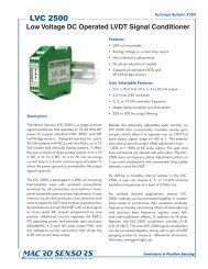
INDUCTIVE <strong>SENSOR</strong>S<br />
(LVDT)<br />
For LVDT sensors, a special transducer<br />
module is available for the rotor electronics.<br />
It generates a sinusoidal distribution voltage<br />
with a choice of 5, 10 or 20 kHz. The sensor<br />
signal is converted into an analog voltage<br />
signal.<br />
The value of any telemetry is determined by<br />
the accuracy of the input measuring amplifier.<br />
Here, because of the large fluctuations<br />
in ambient temperature and the small measuring<br />
signals, a decisive amount depends on<br />
the drift and noise characteristics of the<br />
input measuring amplifier. Even a transmission<br />
technology with 16-bit resolution is<br />
worthless if the characteristics of the input<br />
measuring amplifier are bad. Good antialaising<br />
filters (Butterworth-type) are also<br />
necessary here, of course, in order to avoid<br />
scanning errors.<br />
The RMC sensor telemetry system is distinctive<br />
for its high degree of accuracy. The systems<br />
are available in four zero drift classes:<br />
■<br />
■<br />
■<br />
■<br />
0,02 %/°C<br />
0,01 %/°C<br />
0,003 %/°C (optional)<br />
0,001 %/°C (optional)<br />
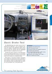
HIGH-PRECISION TORQUE<br />
DATA COLLECTION ON<br />
SERIAL PARTS VIA<br />
ADDITIONAL TEMPERATURE<br />
MEASUREMENT<br />
When torque data is collected on serial<br />
parts to determine their efficiency, temperature<br />
compensation for E-module and zero<br />
point is often extremely expensive. With the<br />
aid of additional temperature measurement<br />
at the measuring point, temperature-related<br />
errors in the measuring computer can be<br />
corrected. For this purpose a 2-channel multiplex<br />
telemetry is utilized, whereby the driving<br />
torque channel is permanently active<br />
(cutoff frequency up to 10 kHz / -3dB) and<br />
the temperature at the measuring point is<br />
scanned on a regular basis.<br />
Automobile drive shaft<br />
6
THE <strong>MULTIPLEX</strong> <strong>SENSOR</strong> <strong>TELEMETRY</strong> PRODUCT PROGRAM<br />
The standard product range comprises a<br />
modular system, enabling value-for-money<br />
solutions for the most varied applications.<br />
Standard interfaces guarantee compatibility<br />
between the modules and ensure later extendibility.<br />
The system contains an extensive range of<br />
standard rotor electronics (sensor signal<br />
amplifiers) in various housings and evaluation<br />
units (receivers).<br />
The systems are available with:<br />
■<br />
■<br />
■<br />
digital transmission technology<br />
(PCM, time division multiplex)<br />
FM technology (time division multiplex)<br />
antenna multiplex<br />
Systems can be delivered with:<br />
■ channel numbers from 2 - 32<br />
■ various shapes of housings<br />
■ miniature 8-channel versions<br />
(22 x 10 x 34 mm), weight 15 g<br />
■ versions for use in environmental<br />
extremes (ambient temperatures of up<br />
to +150 °C)<br />
■ protection type up to IP 67<br />
and various antenna couplings:<br />
■<br />
■<br />
■<br />
■<br />
radial or axial sensing<br />
shaft diameter of up to 3000 mm<br />
antennas for axial sensing integrated into<br />
the rotor electronics<br />
cardan shafts with high freedom of movement<br />
up to ± 100 mm in all directions<br />
plus receivers<br />
■<br />
■<br />
■<br />
■<br />
in 19“ technology (test-stand technology)<br />
plug-in cards<br />
compact designs<br />
PC plug-in cards<br />
... also in miniaturized versions<br />
MANNER<br />
MA<br />
Sensortelemetrie<br />
®<br />
7
DIGITAL TRANSMISSION PCM OR FM TRANSMISSION?<br />
Both methods have their strengths and weaknesses.<br />
MANNER Sensor Telemetry is of<br />
modular design and – depending on the respective<br />
application – features both transmission<br />
methods.<br />
Which of the two methods is more suitable<br />
depends on the problem in hand. FM modulation<br />
(FM technology) is without a doubt the<br />
most interference-free form of transmission.<br />
In digital transmission even one bit error can<br />
falsify the total measuring value by 100%.<br />
There again, digital transmission technology<br />
provides higher resolution, simpler further<br />
processing in the receiver, and the respective<br />
transfer to the measuring data collection<br />
system, since the need for any transducer<br />
is eliminated.<br />
more electronics, and the components necessary<br />
can only be used in a maximum temperature<br />
of approximately 120 °C. Larger space<br />
requirements and limited application temperatures<br />
are thus required. Moreover, the reliability<br />
of the rotor electronics is very dependent<br />
on the number of components that are<br />
needed. Rotor electronics with 8 measuring<br />
channels in a 10 x 22 x 32 mm housing and<br />
featuring PCM technology cannot yet be<br />
realized by today’s technology.<br />
In the case of applications where space is at<br />
a real premium (piston telemetry, gear applications<br />
and environmental extremes with<br />
ambient temperatures of up to +150 °C), FM<br />
technology is producing better results at<br />
present. A digital conversion process requires<br />
DIGITAL TRANSMISSION PCM<br />
On the ”PCM technology“ version, the amplified<br />
and time division multiplex sensor signal<br />
is digitalized, encoded and then transmitted<br />
via the inductive bidirectional line using<br />
an A/D transducer. On systems with higher<br />
resolution each sensor signal is digitalized<br />
and the resulting digital datastreams are<br />
multiplexed. The digitalized sensor signal is<br />
either taken over digitally by the measuring<br />
computer (RS 232/RS 485 or optical link) or is<br />
available as an analog measuring signal<br />
(0 - +10 volts) at the receiver output.<br />
FM TRANSMISSION<br />
On the “PCM technology“ version, the amplified<br />
and time division multiplex sensor signal<br />
is converted using a U/F transducer with<br />
14-bit resolution into a frequency proportional<br />
to the measuring value and transmitted<br />
via the inductive bidirectional line. The<br />
amplified frequency-modulated sensor signal<br />
is either available as an analog measuring<br />
signal (0 - +10 volts) at the receiver output,<br />
or can be directly taken over by the<br />
measuring computer via the RS 232/RS 485<br />
optional interfaces.<br />
ANTENNA <strong>MULTIPLEX</strong><br />
On the “antenna multiplex“ sensor telemetry<br />
version, each amplified sensor signal is<br />
converted into a frequency proportional to<br />
the measuring value via a U/F transducer<br />
with 14-bit resolution and transmitted via the<br />
inductive bidirectional line. Each measuring<br />
channel has its own bidirectional line. The<br />
space requirements per bidirectional line are<br />
10 mm, so 4 transmission channels would<br />
therefore require 40 mm of shaft. With antenna<br />
multiplex up to 40 kHz bandwidth per<br />
channel can be realized.<br />
8
NON-CONTACT ...<br />
Transmission of the measuring signal takes<br />
place inductively, using an antenna pick-up<br />
and an induction loop around the shaft. The<br />
length of the induction loop can amount to<br />
3000 mm, depending on the respective type.<br />
The rotor ring (induction loop with turn) is<br />
wrapped around the shaft. It provides a continuous<br />
guarantee of inductive energy supply<br />
and measuring data transmission.<br />
The rotor ring can...<br />
■<br />
■<br />
be mounted by the customer<br />
be obtained from MANNER by the meter<br />
in various different profiles<br />
■<br />
be obtained from MANNER as a custombuilt<br />
massive ring (for long-term application)<br />
For drive shaft applications the inductive<br />
coupler is equipped with two induction loops<br />
(stator and rotor one wind each). The distance<br />
between the rotor ring and the stator<br />
ring can amount to a maximum of 100 mm.<br />
The loops also come in massive ring versions.<br />
Trigger mark option<br />
When measuring tasks are carried out on<br />
rotating shafts, the turning angle is often required<br />
so that the measuring signal can be<br />
assigned. A reference mark in the form of a<br />
defined pulse can be generated by the system<br />
without extra external components.<br />
EASY-MOUNT ROTOR INDUCTION LOOP<br />
For universal measuring tasks a surfacemountable<br />
rotor ring profile is available by<br />
the meter. For assembly a section is cut from<br />
the roll that corresponds to the respective<br />
shaft diameter; the protective foil is then removed<br />
from the adhesive layer and stuck<br />
around the shaft. The ends are led to the<br />
sensor signal amplifier and soldered on.<br />
Alignment of any kind is unnecessary. The<br />
installation is thus operational within a very<br />
short time indeed, without any time limitation<br />
or the need for any batteries.<br />
The profile consists of the rotor induction<br />
loop with base material and the adhesive<br />
layer. It is only 3 mm high, and a mere 30 mm<br />
wide.<br />
For test-stands<br />
For fatigue-strength installations, divisible<br />
rotor rings in massive design are available.<br />
The rotor rings are custom manufactured at<br />
the factory to suit the shaft diameter. The<br />
two shells are screwed down for subsequent<br />
assembly. The rotor electronics module<br />
can also be optionally mounted into the<br />
rotor ring.<br />
Rotor ring profile<br />
Cover<br />
3 mm<br />
Induction conducter<br />
Adhesive layer<br />
Shaft<br />
MANNER<br />
MA<br />
Sensortelemetrie<br />
®<br />
9
RMC TECHNOLOGY<br />
New RMC technology (remote-controlled<br />
measuring range selection and zero adjustment)<br />
is also available for multiplex systems.<br />
What are the benefits of RMC technology?<br />
You must certainly have been faced by<br />
measuring situations where the measuring<br />
range chosen was either too small or too<br />
large. Subsequent alteration of the measuring<br />
range can often involve high assembly<br />
costs. In cases like these, a rotor electronics<br />
measuring range that is adjustable via the<br />
receiver is extremely useful.<br />
Or what about a measuring situation with a<br />
low input signal that is amplified accordingly<br />
and has no thermal zero drift compensation<br />
whatsoever (e.g. quarter bridge circuit)? Via<br />
the change in ambient temperature the<br />
measuring value slowly but surely leaves the<br />
measuring range. The measurement would<br />
then be over. With RMC technology it is possible<br />
during operation to correct the zero<br />
point by up to 1000% in the most sensitive<br />
measuring range.<br />
Setting the zero point with soldering resistance<br />
can be very hard work indeed in the<br />
case of classic telemetering installations,<br />
especially where major amplifications are<br />
involved. Where numerous measuring channels<br />
are involved, zero setting is an extremely<br />
expensive procedure. With RMC technology<br />
zero setting is totally eliminated. The<br />
measuring bridge is attached and checked<br />
for any connection faults. Defined zero point<br />
displacements can naturally also be set. All<br />
these functions are available online.<br />
Documenting the conditioning parameters!<br />
The conditioning parameters (zero point and<br />
measuring range) of all measuring channels<br />
can be called up via the serial interface and<br />
also programmed as downloads.<br />
What are the distinctive characteristics of<br />
RMC technology?<br />
■<br />
■<br />
■<br />
■<br />
■<br />
■<br />
Amplification (measuring range) can be<br />
set from 0.0625 mV/V to 8 mV/V. The<br />
respective graduation is factor 2.<br />
Depending on the measuring range, the<br />
zero point can be corrected by up to<br />
1000% of the measuring range.<br />
Measuring range selection and zero point<br />
adjustment take place in the rotor electronics<br />
(input measuring amplifier).<br />
The individual measuring ranges are calibrated<br />
in mV/V and the zero point errors<br />
between the measuring ranges have been<br />
eliminated.<br />
Optimal adjustment of the measuring range<br />
means that high resolution and accuracy<br />
are guaranteed in every measuring situation.<br />
A processor in the rotor electronics coordinates<br />
all processes and monitors data<br />
transmission.<br />
Energy<br />
Measuring sensor 1<br />
Power<br />
Sensor<br />
Antialaising<br />
Simultaneous<br />
transfer<br />
Conditioning data<br />
RF<br />
Generator<br />
Simultaneous<br />
Digital/analog transfer<br />
Torque<br />
Pressure<br />
Thermoelement<br />
Piezoresistant<br />
Piezoelectric<br />
supply<br />
Signal<br />
Cal.<br />
Prog.<br />
measuring<br />
amplifier<br />
filter<br />
S&H<br />
Digital measuring data<br />
converter<br />
D/A<br />
S&H<br />
Signal 1<br />
LVDT<br />
Tk<br />
Eddy current sensor<br />
Measuring sensor n<br />
Measuring<br />
value scaling 1<br />
Zero point n<br />
Analog/digital<br />
transducer<br />
Supply<br />
Analog sensor<br />
signal<br />
0 ... +/-10V<br />
Power<br />
Sensor<br />
Antialaising<br />
Simultaneous<br />
transfer<br />
Simultaneous<br />
Digital/analog transfer<br />
Torque<br />
Pressure<br />
Thermoelement<br />
Piezoresistant<br />
Piezoelectric<br />
LVDT<br />
Eddy current sensor<br />
supply<br />
Signal<br />
Kal.<br />
Tk<br />
Prog.<br />
measuring<br />
amplifier<br />
filter<br />
S&H<br />
1 Turn<br />
converter<br />
D/A<br />
S&H<br />
Signal n<br />
High-speed<br />
channel parallel<br />
Shunt calibration 1<br />
Measuring value<br />
Shunt calibration n<br />
scaling n<br />
Zero point n<br />
Logic<br />
Logic<br />
RS 232/RS 485<br />
optional link<br />
Rotor electronics Inductive coupling Stator electronics<br />
Rotor<br />
Power supply for rotor and<br />
sensor signal amplifier<br />
Stator<br />
ü<br />
10
WHEEL-TURN TRANSMITTERS<br />
... AND FURTHER SAMPLE APPLICATIONS<br />
Multiplex telemetry from MANNER is also<br />
available in the form of a wheel-turn transmitter<br />
in vehicle measuring technology,<br />
which transmits any required sensor signals<br />
from a turning wheel. These can be thermoelement<br />
signals, DMS signals or any other<br />
types of signals.<br />
Drive<br />
Ex-Zone<br />
Eexib IICT4<br />
Rotor ring<br />
Shaft<br />
Pick-up<br />
Non-contact<br />
collection of<br />
torque data via<br />
DMS (strain<br />
measurement strip)<br />
Engine speed data<br />
collection<br />
Coaxial cable<br />
max 100 m<br />
Sensor signal<br />
amplifier<br />
Evaluation unit<br />
Torque sensor<br />
Process<br />
control<br />
system<br />
The wheel transmitter is suitable for trips<br />
through puddles (protection type IP 67). An<br />
engine speed impulse track with 360 pulses<br />
per revolution is also available. The number<br />
of channels can be 1, 4, 8 or 16. The transmitter<br />
is connected with the receiver via a<br />
thin coaxial cable. The sensor signals are<br />
available as analog output signals with<br />
0 - ± 10V or as digital signals via the serial<br />
interface.<br />
Temperature sensor<br />
PT100<br />
Process<br />
Mixer<br />
Multiplex transmission<br />
(10 channels)<br />
Process control via sensor telemetry<br />
Temperature data collection up to 150 °C<br />
ambient temperature on clutch thrust plate<br />
Shear and torque measurement on drive<br />
shaft<br />
Torque data collection with temperature<br />
measurement on gas turbine output shaft<br />
MANNER<br />
®<br />
11<br />
MA<br />
Sensortelemetrie
<strong>MULTIPLEX</strong> <strong>SENSOR</strong> <strong>TELEMETRY</strong> – THE PRODUCT PROGRAM<br />
Multiplex sensor telemetry<br />
(product family)<br />
Time division multiplex<br />
Digital transmission (PCM)<br />
FM transmission<br />
Antenna multiplex<br />
System<br />
data<br />
Resolution Channel numbers Sensing rates<br />
12 Bit 2 16 10 000 Samples/sec<br />
14 Bit* 4 24 25 000 Samples/sec<br />
8 32 50 000 Samples/sec<br />
100 000 Samples/sec<br />
Signal dyn. Channel numbers Sensing rates<br />
66 dB 2 16 1 000 Samples/sec<br />
4 24 2 000 Samples/sec<br />
8 32 10 000 Samples/sec<br />
25 000 Samples/sec<br />
Signal dyn. Channel numbers Cutoff frequencies<br />
66 dB 2 5 1 kHz (-3 dB)<br />
3 6 10 kHz (-3 dB)<br />
4 7 40 kHz (-3 dB)<br />
Accuracy<br />
class<br />
Zero point and amplification drift at 1 mV/V<br />
0.01 %/°C<br />
0.003 %/°C<br />
Zero point and amplification drift at 1 mV/V<br />
0,02 %/°C<br />
0,01 %/°C<br />
Zero point and amplification drift at 1 mV/V<br />
0,01 %/°C<br />
0,003 %/°C<br />
0,001 %/°C<br />
Ambient<br />
temperature<br />
range<br />
- 10 ° ... + 85 °C<br />
- 25 ° ... + 125°C<br />
- 10 ° ... + 85 °C<br />
- 25 ° ... + 125 °C<br />
- 40 ° ... + 150 °C<br />
- 10 ° ... + 85 °C<br />
- 25 ° ... + 125 °C<br />
- 40 ° ... + 150 °C<br />
Acceleration<br />
stability<br />
10 000 g<br />
20 000 g<br />
20 000 g<br />
100 000 g<br />
20 000 g<br />
100 000 g<br />
Sensing<br />
radial/axial<br />
radial/axial<br />
radial/axial<br />
Housing<br />
variants<br />
• ALU cuboid<br />
• ALU cartridge<br />
• ALU cuboid<br />
• ALU cartridge<br />
• Epoxy resin coated<br />
• Miniature<br />
• Channel number + flat chip<br />
15 x 8 x 32 mm<br />
RMC-option<br />
remote-controlled<br />
measuring range<br />
and zero point selec.<br />
Measuring range 0.0625 mV/V ... 8 mV/V<br />
Zero point: 1000 % in smallest meas. range<br />
Measuring range 0.0625 mV/V ... 8 mV/V<br />
Zero point: 1000 % in smallest meas. range<br />
Measuring range 0.0625 mV/V ... 8 mV/V<br />
Zero point: 1000 % in smallest meas. range<br />
Trigger mark<br />
Optional<br />
Optional<br />
–<br />
Data interface<br />
RS 232/RS 485<br />
optional link<br />
Optional<br />
Optional in combination with RMC<br />
Optional in combination with RMC<br />
Single-channel<br />
cut-in<br />
–<br />
remote-controlled meas. point selection switch remote-controlled meas. point selection switch<br />
Simultaneous<br />
sensing<br />
Optional<br />
Optional<br />
–<br />
Wheel-turn<br />
transmitter<br />
–<br />
Compact design (transmitter with bearings)<br />
engine speed output 360 pulses/rev.<br />
IP 67<br />
–