Lec 15 DC Motors I(pdf) - KFUPM Open Courseware
Lec 15 DC Motors I(pdf) - KFUPM Open Courseware
Lec 15 DC Motors I(pdf) - KFUPM Open Courseware

Create successful ePaper yourself
Turn your PDF publications into a flip-book with our unique Google optimized e-Paper software.
EE 360 ELECTRIC ENERGY<br />
LECTURE <strong>15</strong><br />
<strong>DC</strong> <strong>Motors</strong>-I<br />
The material covered in this lecture will be as follows:<br />
1) The performance of <strong>DC</strong> motors<br />
2) The torque speed relationship of <strong>DC</strong> motors<br />
At the end of this lecture you should be able to:<br />
To explain the performance of <strong>DC</strong> motors<br />
Understand the torque speed relationship of <strong>DC</strong> motors<br />
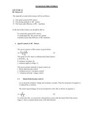
1. Performance of <strong>DC</strong> <strong>Motors</strong><br />
The equivalent circuit of <strong>DC</strong> motors is similar to the equivalent circuit of <strong>DC</strong> generators,<br />
except that the direction of the current enters the armature circuit.<br />
Φ<br />
V a<br />
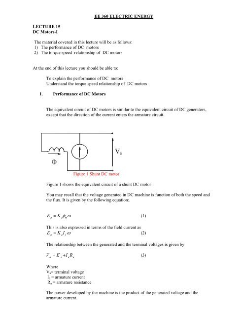
Figure 1 Shunt <strong>DC</strong> motor<br />
Figure 1 shows the equivalent circuit of a shunt <strong>DC</strong> motor<br />
You may recall that the voltage generated in <strong>DC</strong> machine is function of both the speed and<br />
the flux. It is given by the following equation:.<br />
E<br />
= K φ ω<br />
(1)<br />
a a m<br />
This is also expressed in terms of the field current as<br />
E = K I ω<br />
(2)<br />
a a f<br />
The relationship between the generated and the terminal voltages is given by<br />
V<br />
a<br />
= E<br />
a+ IaRa<br />
(3)<br />
Where<br />
V a = terminal voltage<br />
I a = armature current<br />
R a = armature resistance<br />
The power developed by the machine is the product of the generated voltage and the<br />
armature current.
P = ωT = E I<br />
(4)<br />
dev a a<br />
The torque developed by the machine is given by<br />
T = kaφmIa<br />
(5)<br />
Equation 4 shows that the machine torque is function of the magnetic flux and the current<br />
drawn by the machine.<br />
The torque equation can also be written in terms of the field current and the machine constant.<br />
T = k I I<br />
(6)<br />
a f a<br />
Using equations 1 and 3, the speed of a <strong>DC</strong> motor is expressed in equation 5.<br />
ω<br />
V<br />
− I R<br />
a a a<br />
= (7)<br />
K<br />
aφm<br />
Equation 5 is referred to as speed equation of <strong>DC</strong> motors. It contains all factors that affect the<br />
speed of the motor.<br />
1. 1 Speed Regulation<br />
One measure of the performance of <strong>DC</strong> motors is the speed regulation. It is defined as<br />
It is defined as the change of speed from no load to full load operating condition of the motor.<br />
Equation 8 defines the speed regulation in terms of the no-load and full load speeds.<br />
w<br />
Speed Regulation=<br />
nl −ω<br />
fl<br />
x 100<br />
ω<br />
fl<br />
(8)<br />
Where<br />
ω<br />
nl<br />
= no load speed of the motor in radians per second<br />
ω = full load speed of the motor in radians per second<br />
fl<br />
Equations 8 is also written as<br />
nnl<br />
−nfl<br />
Speed Regulation= x 100<br />
nfl<br />
n<br />
nl<br />
= no load speed of the motor in rpm<br />
n = full load speed of the motor in rpm<br />
fl<br />
(9)<br />
Example 1<br />
A 25 kW, 250 V, shunt motor has an armature resistance of Ra = 0.25 ohm, and a field coil<br />
resistance of R f = 125 ohms. At rated terminal voltage the motor current is 12 A and runs at<br />
1000 rpm.<br />
(a) Draw the equivalent circuit.<br />
b) Calculate the motor constant<br />
c) Calculate the speed, speed regulation and torque at full load conditions
Solution<br />
(a) The Equivalent Circuit<br />
0.25<br />
I<br />
I a<br />
E a<br />
Φ f<br />
125<br />
250 V<br />
(b) Machine constant:<br />
Calculation of field current:<br />
I f = 250 / 125 = 2 A<br />
The armature current at no load is:<br />
I a = 12 - 2 = 10 A<br />
Generated voltage at no load is:<br />
Ea = V a - I a Ra = 250 - (10)(0.25) = 247.5 V<br />
No load speed:<br />
2xπ<br />
x1000 ω = = 104.72 rad/ sec<br />
60<br />
• Machine constant:<br />
Ea = KaI fω<br />
247.5= Kx<br />
a<br />
2x<br />
104.72<br />
247.5<br />
K a<br />
= = 1.187<br />
2x<br />
104.72<br />
c. Speed and Torque at full load<br />
Motor terminal input current:<br />
I t = 25000 / 250 = 100 A<br />
• The armature current is:<br />
I a = 100 - 2 = 98 A<br />
• Generated voltage at full load is:<br />
E a = V a - I a Ra = 250 - (98)(0.25) = 225.5 V<br />
• Motor speed at full load:<br />
E<br />
a<br />
ω =<br />
KI<br />
a<br />
f
ω = 225.5<br />
94.98 rad / sec<br />
1.187x<br />
2<br />
=<br />
The motor speed in rpm is<br />
60x<br />
ω<br />
n =<br />
2x<br />
π<br />
60x<br />
94.98<br />
n= = 907.06 rpm<br />
2x π<br />
Speed regulation= 1000 − 907.06 x 100 = 10.24%<br />
907.06<br />
• Torque at full load:<br />
Using equation 4, the motor torque is given as<br />
EI<br />
a a<br />
225.5x<br />
98<br />
T = = = 232.67 Newtons − meter<br />
ω 94.98<br />
m<br />
Example 2<br />
A <strong>DC</strong> motor develops a torque of 30 N-m. Determine the torque when the armature<br />
current is increased by 50% and the flux is reduced by 10%.<br />
Solution<br />
Recall that the motor torque is function of the armature current and flux as given by<br />
equation 5 earlier.<br />
T = kaφmIa<br />
Let the initial toque and the corresponding variable be referred to by subscript (1)<br />
Let the final toque and the corresponding variable be referred to by subscript (2)<br />
T = k φ I<br />
T = k φ I<br />
1 a m1 a1<br />
2 a m2 a2<br />
T<br />
2<br />
k φ I<br />
=<br />
T k φ I<br />
1<br />
a m2 a2<br />
a m1 a1<br />
I a2 =1.5xI a1<br />
φ = 0.9φ<br />
m2 m2<br />
T<br />
2<br />
k 0.9φ<br />
x1.5I<br />
=<br />
T k φ I<br />
1<br />
a m1` a1<br />
a m1 a1<br />
T<br />
= T<br />
2 1<br />
k 0.9φ<br />
x1.5I<br />
k φ I<br />
a m1` a1<br />
a m1 a1<br />
T2 = 30x0.9x1.5 = 40.5 N − m<br />
2. Speed Torque Characteristics of <strong>DC</strong> <strong>Motors</strong>
In order to understand the speed torque characteristics, we shall rewrite equations 5 and 7<br />
again.<br />
T = k φ I<br />
(10)<br />
ω<br />
V<br />
a m a<br />
− I R<br />
a a a<br />
= (11)<br />
K<br />
aφm<br />
The armature current can be expressed in terms of the torque and the flux<br />
I<br />
a<br />
T<br />
= (12)<br />
k φ<br />
m<br />
Substitute equation 12 into equation 11.<br />
V<br />
a<br />
Ra<br />
ω = T<br />
2<br />
K φ<br />
− ( K φ )<br />
(13)<br />
a m a m<br />
Equation 13 is referred to as the speed-torque equation.<br />
If the applied voltage and the flux remain constant, the speed will decrease linearly with<br />
the torque.<br />
This is the case of an ideal shunt motor.<br />
In an actual machine, the flux decreases slightly as the load increases due to armature<br />
reaction.<br />
This means there is a less reduction in speed.<br />
In case of a series motor, the field is connected in series with the armature.<br />
The flux is thus a function of the armature current and the torque equation is written as<br />
follows.<br />
T<br />
= k I<br />
(14)<br />
' 2<br />
a a<br />
The speed can than be expressed as<br />
ω = V<br />
a<br />
Ra<br />
'<br />
'<br />
K<br />
aI<br />
− a<br />
K<br />
(<strong>15</strong>)<br />
Substitute for I a in terms of the torque of equation 14.<br />
V Ra<br />
ω = − (16)<br />
'<br />
K T K<br />
a<br />
''<br />
a<br />
The speed of the series motor can be dangerously high at low or no-load torques.<br />
Therefore, series motors is never started with no-load connected to its shaft.<br />
The operation of a compound machine lies between the characteristics of shunt and<br />
series motors.
When the two mmf are additive, the characteristics of the compound motor is more<br />
drooping than that of a shunt motor.<br />
When the two mmf are opposing, the characteristics of the compound motor lie above<br />
that of a shunt motor.<br />
Figure 3 shows typical speed-toque characteristics of <strong>DC</strong> motors.<br />
Figure 3 Speed-toque characteristics of <strong>DC</strong> motors.<br />
Example 3<br />
A 10-hp 230-V <strong>DC</strong> series motor has a line current of 37 A and a rated speed of 1200 rpm.<br />
The armature and series field resistances are 0.4 Ω and 0.2 Ω respectively. The total brush<br />
voltage drop is 2 V. Calculate the following:<br />
a. Speed at a line current of 20 A.<br />
b. No-load speed when the line current is 1 A.<br />
c. Speed at <strong>15</strong>0% of the rated load when the line current is 60 A and the series field flux is<br />
125% of the full load flux.<br />
Solution<br />
At full load I a1 , the generated back emf is given by<br />
E a1 = V a -I a1 (R s +R a )-Brush drop<br />
E a1 = 230-37(0.4+0.2)-2= 205.8 V<br />
(a) When the load current I a2 is 20 A,<br />
E a2 = 230-20(0.4+0.2)-2= 216 V<br />
E K φω K I n<br />
E K K I n<br />
'<br />
a2 a 2 2 a a2 2<br />
= =<br />
'<br />
a1 aφω<br />
1 1 a a1 1<br />
The speed n 2 is given by<br />
E I (216) x37<br />
n = n = x1200=<br />
2330rpm<br />
(205.8) x 20<br />
a2 a1<br />
2 1<br />
Ea1Ia2<br />
(b) No-load speed
The armature current I a3 = 1.0 A<br />
E a3 = 230-1(0.4+0.2)-2= 227.4 V<br />
Ea3Ia1<br />
(227.4) x37 n3 = n1<br />
= x 1200 = 49,060 rpm<br />
E I (205.8) x1<br />
a1 a3<br />
This confirms the statement that <strong>DC</strong> series motors should never be run at no-load as the<br />
speed is dangerously high.<br />
c. Speed at 60 A armature current<br />
I a4 = 60.0 A<br />
E a4 = 230-60(0.4+0.2)-2= 192 V<br />
The series flux is 125% of the full load flux.<br />
φ = 1.25φ<br />
4 1<br />
E (192) x<br />
n = φ<br />
n = φ<br />
x1200 1399rpm<br />
φ<br />
=<br />
a 4 1 1<br />
4 1<br />
Ea1φ4 (205.8) x1.25<br />
1