experiment # uo1 double effect evaporator - KFUPM Open ...
experiment # uo1 double effect evaporator - KFUPM Open ...
experiment # uo1 double effect evaporator - KFUPM Open ...

Create successful ePaper yourself
Turn your PDF publications into a flip-book with our unique Google optimized e-Paper software.
EXPERIMENT # UO1<br />
DOUBLE EFFECT EVAPORATOR<br />
OBJECTIVE:<br />
The objective of this <strong>experiment</strong> is to study the performance of a <strong>double</strong> <strong>effect</strong><br />
<strong>evaporator</strong>. Mass and energy balances will be carried out to determine steam<br />
economy and heat transfer coefficients.<br />
INTRODUCTION<br />
Evaporation is a process whereby a solution consisting of a volatile solvent and<br />
a non-volatile solute is concentrated by vaporizing the solvent. Common types<br />
of <strong>evaporator</strong>s used in the industry include i.) forced circulation <strong>evaporator</strong>s,<br />
ii.) natural circulation <strong>evaporator</strong>s (thermosiphon), iii.) falling film<br />
<strong>evaporator</strong>s, and iv.) rising film <strong>evaporator</strong>s. Drying differs from evaporation<br />
in that the product in this case is solid.<br />
In many industrial applications, water is used as the solvent while steam is<br />
utilized as heating medium for the vaporization process. In such cases, given<br />
efficient heat exchange, one kilogram of water may be evaporated per kilogram<br />
of steam condensed.<br />
To improve steam economy, multiple <strong>evaporator</strong>s are used. The basic<br />
principle involved is to utilize steam generated in one <strong>effect</strong> as the source of<br />
heat for the subsequent <strong>evaporator</strong>. In this way, multiple <strong>effect</strong> <strong>evaporator</strong>s<br />
have the capacity to significantly reduce steam consumption.<br />
THEORETICAL BACKGROUND<br />
Steam economy, which is defined as the mass of water vapor generated per<br />
mass of steam is the process parameter most significant in evaluating the<br />
performance of multiple <strong>effect</strong> <strong>evaporator</strong>s (Equation 1). The other important<br />
parameter upon which both the evaporation and condensation process depend<br />
is the heat transfer coefficient (Equation 2).<br />
Steam Economy :<br />
m<br />
m<br />
v<br />
E = (1)<br />
s<br />
Heat Transfer Rate: q = UAΔT (2)<br />
UO1-1
ΔT for both <strong>effect</strong>s should be considered. For U 1 , ΔT=T s – T 1 , and for U 2 ,<br />
ΔT=T 1 – T 2 .<br />
MASS AND ENERGY BALANCES<br />
Assuming that the stream entering the <strong>effect</strong> is saturated and that the<br />
condensate resulting from the steam is not sub cooled, then the total heat<br />
transfer in the <strong>effect</strong> is obtained as :<br />
q = m s .λ s<br />
-(3)<br />
The heat given up by the condensing steam is absorbed by the process fluid and<br />
used for partial vaporization. From mass and enthalpy balance,<br />
q = ( m − m ) H + m H − m H<br />
-(4)<br />
f p v p p f f<br />
Values of enthalpies at the <strong>experiment</strong>al conditions of temperature and pressure<br />
should be obtained from literature. The flow rates of various streams are<br />
determined from <strong>experiment</strong>al data.<br />
PROCESS DESCRIPTION AND EXPERIMENTAL PROGRAM<br />
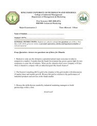
The <strong>double</strong> <strong>effect</strong> <strong>evaporator</strong> unit is shown schematically in Figure 1.The two<br />
<strong>effect</strong>s are initially filled to desired operating levels. Steam is supplied to the<br />
first <strong>effect</strong> where heat transfer takes place causing partial evaporation of water<br />
in the <strong>effect</strong>. The vapor generated is then supplied to the second <strong>effect</strong> where it<br />
is used to vaporize some of the liquid water in the <strong>evaporator</strong>. Vapor produced<br />
in the second <strong>effect</strong> is subsequently condensed and collected in the receiving<br />
tank.<br />
The entire <strong>experiment</strong>al unit is to be operated at steady state for analysis. At<br />
steady state, process parameters such as pressures, temperatures, mass flow<br />
rates and tank level are measured and recorded as shown in the log sheet. The<br />
measurements are repeated three times at regular intervals for reproducibility.<br />
UO1-2
P2<br />
m v1<br />
P4<br />
m v2<br />
T3<br />
P5<br />
T1<br />
FIRST<br />
EFFECT<br />
CYCLONE<br />
I<br />
T2<br />
SECOND<br />
EFFECT<br />
CYCLONE<br />
II<br />
CONDENSER<br />
T4<br />
C3<br />
Steam<br />
P1<br />
P3<br />
CONDENSATE<br />
TANK<br />
T5<br />
Feed Water F1<br />
m p1<br />
m p2<br />
C1<br />
FIGURE 1 : DOUBLE EFFECT EVAPORATOR<br />
C2<br />
UO1-3<br />
Data:<br />
Condensate Tank Diameter D = 50 cm<br />
Evaporator Heat A = 0.51m 2<br />
Transfer Area<br />
C : Condensate<br />
P : Pressure Indicator<br />
T : Temperature Indicator
EXPERIMENTAL PROCEDURE<br />
1. Start the unit and let it reach steady state (to be done with the help of<br />
technician).<br />
2. After the unit reaches steady state, record the temperature and pressure at<br />
various points as shown in the log sheet.<br />
3. Measure the flow rate of condensate from the first <strong>effect</strong> by collecting a<br />
quantity of the condensate in a given time.<br />
4. Repeat steps (3) for the second <strong>effect</strong>.<br />
5. Measure the flow rate of the condensate flowing into the receiving tank by<br />
monitoring the rise in the level in the tank.<br />
6. Repeat steps (3) to (5) two more times.<br />
7. Shut down the unit. (To be done with the help of technician).<br />
DATA ANALYSIS<br />
The following items must be covered in the data analysis and the analysis sheet<br />
filled in accordingly:<br />
1) Tabulate all enthalpies used in analysis from literature.<br />
2) Carry out a mass and energy balance for the two <strong>effect</strong>s.<br />
3) Determine the steam economy of the process.<br />
4) Determine the overall heat transfer coefficients for thde two <strong>effect</strong>s.<br />
Notations:<br />
A Surface area of heat transfer , m 2<br />
E<br />
Steam Economy<br />
Hv, Hf , Hp Enthalpies of the vapor, the feed and the product, W/m 2 .K<br />
m f , m p , m s mass flow rate of the feed, product and steam supplied<br />
kg/hr<br />
m v1<br />
mass flow rate of vapor from first <strong>effect</strong>, (= C2) kg/hr<br />
m v2<br />
mass flow rate of vapor from second <strong>effect</strong>, (= C2) kg/hr<br />
q heat transfer rate, W.<br />
T p<br />
temperature of the process fluid, K<br />
T s<br />
temperature of the steam supplied, K<br />
U overall heat transfer coefficient, W/m 2 .K<br />
λ<br />
Latent heat of vaporization, J/kg<br />
UO1-4
References:<br />
1.) Kern, D. Q., Process Heat Transfer, McGraw Hill, (1965)<br />
2.) Perry, R.H. and Chilton, C.H., "Chemical Engineers' Handbook", 5th<br />
Edition, McGraw-Hill Book Company NY, chap 20 (1973).<br />
3.) Thompson, E.V., and Ceckler, W.H., "Introduction to Chemical<br />
Engineering.", McGraw-Hill Book Company, NY, chap.17 (1977).<br />
UO1-5
TABLE 1. LOG SHEET FOR EXPERIMENT UO1<br />
Date :<br />
Name of students: 1)<br />
2)<br />
3)<br />
Signature of Instructor:<br />
Tag Description Units Set 1 Set 2 Set 3<br />
PI-1 Fresh steam pressure Psig<br />
PI-2 Vap. pr. in the 1 st <strong>effect</strong> "<br />
PI-3 Steam pr. in the 2nd <strong>effect</strong> "<br />
PI-4 Vapor pr. in the 2nd <strong>effect</strong> In. Hg<br />
PI-5 Shell side pr. in the cond. "<br />
TI-1 Vap temp in the 1st <strong>effect</strong> oF<br />
TI-2 Vap temp in the 2nd <strong>effect</strong> "<br />
TI-3 Vap temp at cond. Inlet "<br />
TI-4 Temp at condenser outlet "<br />
TI-5 Feed temperature "<br />
FI-1 Feed flow rate LPM<br />
Weight of cond (1st <strong>effect</strong>)<br />
Flow time (1st <strong>effect</strong>)<br />
Weight of cond (2nd <strong>effect</strong>)<br />
Flow time (2nd <strong>effect</strong>)<br />
kg<br />
min.<br />
kg<br />
min.<br />
LI-3 Rise in tank level cm<br />
Diameter of Tank cm 50<br />
Total Time<br />
Weight of empty bucket<br />
Weight of empty bucket<br />
with condensate<br />
min.<br />
kg<br />
kg<br />
UO1-6
TABLE 2. ENTHALPY TABULATION<br />
Temperature Pressure Enthalpy Ref.<br />
T1 P2 H v1 =<br />
" " H p1 =<br />
T5 1 atm. H f1 =<br />
T2 P4 H v2 =<br />
" " H p2 =<br />
T sat P1 λ1 =<br />
T sat P3 λ2 =<br />
TABLE 3. CALCULATION SUMMARY<br />
(Details to be shown elsewhere)<br />
Parameter Value Units<br />
Feed flow rate to 1st <strong>effect</strong><br />
kg/h<br />
Vapor flow rate from 1st <strong>effect</strong> "<br />
Condensate flow rate from 1st <strong>effect</strong> "<br />
Steam Economy of 1st <strong>effect</strong><br />
Vapor flow rate from 2nd <strong>effect</strong><br />
kg/h<br />
Condensate flow rate from 2nd <strong>effect</strong> "<br />
Steam Economy of 2nd <strong>effect</strong><br />
Heat transfer area of H01,H02 0.51 m2<br />
Overall heat transfer coefficient of 1st <strong>effect</strong><br />
W/m2.K<br />
Overall heat transfer coefficient of 2nd <strong>effect</strong> "<br />
Overall Steam Economy of process<br />
UO1-7
UO1-8