

Dual manifolds and differential by-pass valve - Caleffi
Dual manifolds and differential by-pass valve - Caleffi
Dual manifolds and differential by-pass valve - Caleffi

You also want an ePaper? Increase the reach of your titles
YUMPU automatically turns print PDFs into web optimized ePapers that Google loves.
<strong>Dual</strong> <strong>manifolds</strong> <strong>and</strong><br />
<strong>differential</strong> <strong>by</strong>-<strong>pass</strong> <strong>valve</strong><br />
series 356 - 357<br />
Technical specification<br />
Material: brass EN 12165 CW617N<br />
Main connections: 3/4” <strong>and</strong> 1” F<br />
Branch connections: 23 p. 1,5 M - Ø 18 mm<br />
Main connections centre distance: 60 mm<br />
Branch centre distance: 40 mm<br />
Average internal diameter: 3/4”: Ø 20 mm<br />
1”: Ø 26 mm<br />
Max working pressure: 10 bar<br />
Temperature range: -10÷110°C<br />
Constructional details<br />
These <strong>manifolds</strong> are made out of a single monoblock casting,<br />
without the need for additional connections between the internal<br />
tubes. This eliminates a possible cause of problems due to the<br />
joining of metals with different thermal expansion coefficients.<br />
The connections of the side branches are at right angles to the main<br />
headers, to allow for easier connections.<br />
Hydraulic characteristics<br />
Localized loss factor ξ of inlet connections (F+R): 3,0<br />
Localized loss factor ξ of branches (F+R): 6,5<br />
01014/03 GB<br />
Function<br />
<strong>Dual</strong> <strong>manifolds</strong> are typically used for the distribution of<br />
heat-carrying fluid in heating <strong>and</strong> air conditioning systems. They<br />
are available with both double side <strong>and</strong> single side connections<br />
<strong>and</strong> can be used to connect copper, plastic or multi-layer piping.<br />
The <strong>differential</strong> <strong>by</strong>-<strong>pass</strong> <strong>valve</strong> keeps the manifold flow <strong>and</strong> return<br />
circuits pressure balanced when the flow rate varies. This<br />
variation in flow rate can take place following the closure of room<br />
temperature regulating <strong>valve</strong>s on the heat emitters - for example,<br />
thermostatic or electrothermal <strong>valve</strong>s.<br />
Product range<br />
MANIFOLDS:<br />
Series 356 double side connections Sizes 3/4” <strong>and</strong> 1”<br />
Series 357 single side connections Size 3/4”<br />
DIFFERENTIAL BY-PASS VALVE:<br />
Code 356050 Size 3/4”<br />
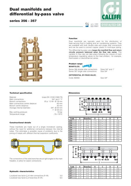
Dimensions<br />
Code<br />
356502<br />
356504<br />
356506<br />
356508<br />
356510<br />
356604<br />
356606<br />
356608<br />
356610<br />
356612<br />
A A<br />
60<br />
B<br />
Code<br />
357502<br />
357503<br />
357504<br />
357505<br />
357506<br />
B<br />
60<br />
A A<br />
A<br />
3/4“<br />
3/4“<br />
3/4“<br />
3/4“<br />
3/4“<br />
1“<br />
1“<br />
1“<br />
1“<br />
1“<br />
A<br />
3/4“<br />
3/4“<br />
3/4“<br />
3/4“<br />
3/4“<br />
CALEFFI<br />
Branches<br />
2+2<br />
4+4<br />
6+6<br />
8+8<br />
10+10<br />
4+4<br />
6+6<br />
8+8<br />
10+10<br />
12+12<br />
40<br />
CALEFFI<br />
Branches<br />
2+2<br />
3+3<br />
4+4<br />
5+5<br />
6+6<br />
cert. n° 0003<br />
ISO 9001<br />
Mod. Dep.<br />
40<br />
B<br />
116<br />
116<br />
116<br />
116<br />
116<br />
122<br />
122<br />
122<br />
122<br />
122<br />
B<br />
105<br />
105<br />
105<br />
105<br />
105<br />
E<br />
C<br />
C<br />
23 p.1,5<br />
23 p.1,5<br />
23 p.1,5<br />
23 p.1,5<br />
23 p.1,5<br />
23 p.1,5<br />
23 p.1,5<br />
23 p.1,5<br />
23 p.1,5<br />
23 p.1,5<br />
Mod. Dep. CALEFFI<br />
357<br />
73<br />
E<br />
CALEFFI<br />
C<br />
23 p.1,5<br />
23 p.1,5<br />
23 p.1,5<br />
23 p.1,5<br />
23 p.1,5<br />
C<br />
356<br />
D<br />
D<br />
30<br />
30<br />
30<br />
30<br />
30<br />
32<br />
32<br />
32<br />
32<br />
32<br />
Mod. Dep.<br />
D<br />
30<br />
30<br />
30<br />
30<br />
30<br />
357<br />
E<br />
100<br />
180<br />
260<br />
340<br />
420<br />
184<br />
264<br />
344<br />
424<br />
538<br />
D<br />
E<br />
180<br />
260<br />
373<br />
453<br />
533
Technical specification of <strong>by</strong>-<strong>pass</strong><br />
Material: brass EN 12165 CW617N<br />
Seals: EPDM<br />
Max working pressure: 10 bar<br />
Temperature range: -10÷110°C<br />
Connections to manifold: 3/4” adjustable nut<br />
Head connections: 3/8” (with plug)<br />
Centre distance: 60 mm<br />
Hydraulic characteristics<br />
By-<strong>pass</strong> <strong>differential</strong> pressure: 20 kPa (2000 mm w.g.)<br />
∆P (mm w.g.)<br />
10000<br />
9000<br />
8000<br />
7000<br />
6000<br />
5000<br />
4500<br />
4000<br />
3500<br />
3000<br />
2500<br />
2000<br />
1800<br />
1600<br />
1400<br />
1200<br />
1000<br />
50<br />
60<br />
70<br />
80<br />
90<br />
100<br />
120<br />
140<br />
160<br />
180<br />
200<br />
250<br />
300<br />
350<br />
400<br />
450<br />
500<br />
600<br />
700<br />
800<br />
900<br />
90<br />
80<br />
70<br />
60<br />
30<br />
25<br />
12<br />
Q (l/h)<br />
∆P (kPa)<br />
100<br />
50<br />
45<br />
40<br />
35<br />
20<br />
18<br />
16<br />
14<br />
1000<br />
10<br />
Dimensions<br />
B B<br />
A A<br />
SPECIFICATION SUMMARIES<br />
Code<br />
356050<br />
Series 356<br />
<strong>Dual</strong> manifold in monoblock casting with double side connections. Brass body. Main connections 3/4” or 1”.<br />
Branch connections 23 p.1,5 M - Ø 18 mm. Main centre distance 60 mm. Branch centre distance 40 mm. Maximum<br />
working pressure 10 bar. Temperature range -10÷110°C.<br />
Series 357<br />
<strong>Dual</strong> manifold in monoblock casting with single side connections. Brass body. Main connections 3/4” or 1”.<br />
Branch connections 23 p.1,5 M - Ø 18 mm. Main centre distance 60 mm. Branch centre distance 40 mm. Maximum<br />
working pressure 10 bar. Temperature range -10÷110°C.<br />
Code 356050<br />
Differential <strong>by</strong>-<strong>pass</strong> <strong>valve</strong> for dual <strong>manifolds</strong>. Brass body. Connections to manifold 3/4” with adjustable nut.<br />
Head connections 3/8” with plug. EPDM seals. Temperature range -10÷110°C. Maximum working pressure 10 bar.<br />
Centre distance 60 mm. Fixed <strong>differential</strong> pressure calibration 20 kPa.<br />
C<br />
Application diagram<br />
3 · · · 4<br />
2 · · ·<br />
4<br />
· 3 · · ·<br />
Thermostatic <strong>valve</strong><br />
3 · · · · · · 2<br />
4<br />
2 · ·<br />
D<br />
CALEFFI<br />
Mod. Dep. CALEFFI<br />
We reserve the right to change our products <strong>and</strong> their relevant technical data, contained in this publication, at any time <strong>and</strong> without prior notice.<br />
CALEFFI<br />
CALEFFI S.P.A. · I · 28010 FONTANETO D’AGOGNA (NO) · S.R. 229, N.25 · TEL.INT. +39 0322 8491 R.A. · FAX +39 0322 863723<br />
· Http://www.caleffi.com · E-mail: info@caleffi.it ·<br />
357<br />
356<br />
3 · · · 4<br />
2 · · ·<br />
A<br />
3/4”<br />
Mod. Dep.<br />
CALEFFI<br />
Mod. Dep.<br />
357<br />
B<br />
3/8”<br />
C<br />
60<br />
D<br />
55


