Design and Simulation of a Low Power Viterbi Decoder using ...
Design and Simulation of a Low Power Viterbi Decoder using ...
Design and Simulation of a Low Power Viterbi Decoder using ...

Create successful ePaper yourself
Turn your PDF publications into a flip-book with our unique Google optimized e-Paper software.
International Journal <strong>of</strong> Computer Applications (0975 – 8887)<br />
Volume 84 – No 2, December 2013<br />
<strong>Design</strong> <strong>and</strong> <strong>Simulation</strong> <strong>of</strong> a <strong>Low</strong> <strong>Power</strong> <strong>Viterbi</strong> <strong>Decoder</strong><br />
<strong>using</strong> Constraint Length Nine<br />
K.Lakshmi Narayana 2<br />
A.Jaya Lakshmi 3<br />
A.Mallaiah 1<br />
College, Gudlavalleru, India 1<br />
Gudlavalleru Engineering<br />
Gudlavalleru, India 2<br />
Associate Pr<strong>of</strong>essor<br />
Department <strong>of</strong> ECE,<br />
PG Student Gudlavalleru<br />
Engineering College,<br />
Assistant Pr<strong>of</strong>essor<br />
Department <strong>of</strong> ECE,<br />
Vardhaman Engineering<br />
College, Hyderabad, India 3<br />
ABSTRACT<br />
<strong>Viterbi</strong> <strong>Decoder</strong> is the dominant module to determining the<br />
power consumption <strong>of</strong> the system. High speed <strong>and</strong> low power<br />
design <strong>of</strong> <strong>Viterbi</strong> <strong>Decoder</strong> with data rate1/2 <strong>and</strong> convolution<br />
encoding with a constraint length K = 9 is presented in this<br />
paper. The Proposed <strong>Viterbi</strong> decoder can be reduce the power<br />
consumption without reducing the decoding speed <strong>and</strong> also<br />
increases the length <strong>of</strong> the bits. The operating frequency <strong>of</strong><br />
convolution encoder <strong>and</strong> <strong>Viterbi</strong> decoded is 306.65MHz <strong>and</strong><br />
power consumption is 45.01Mw <strong>using</strong> Xpower tools in Xilinx<br />
<strong>and</strong> Spartan 3E FPGA kit.<br />
Keywords<br />
<strong>Viterbi</strong> decoder, <strong>Low</strong> power, Xilinx power estimator,<br />
Spartan3E, high speed.<br />
1. INTRODUCTION<br />
In today’s digital communications, the reliability <strong>and</strong> efficiency<br />
data transmission is most concerning issue for communication<br />
channels. Error correction technique acts as a important role in<br />
communication systems. The error correction technique<br />
increases the capacity by adding redundant information for the<br />
source data transmission.<br />
In the late 1940’s the approach to error correction coding taken<br />
by modern digital communications system started with ground<br />
breaking work <strong>of</strong> Shannon, Hamming <strong>and</strong> Golay. The<br />
theoretical limits <strong>of</strong> reliable communication were defined by<br />
the Shannon while Hamming <strong>and</strong> Golay were developing the<br />
first practical error control schemes. The Hamming codes <strong>and</strong><br />
Golay codes are categorized as a linear block codes.<br />
In 1954, a new class <strong>of</strong> linear block codes named Reed-Muller<br />
codes were discovered by Muller[4]. Reed-Muller Codes<br />
allowed more flexibility in the size <strong>of</strong> the code <strong>and</strong> the number<br />
<strong>of</strong> correctable errors per code word. The following discovery<br />
code was the cyclic codes[10]. Cyclic codes are also called<br />
cyclic redundancy check (CRC) codes primarily used today for<br />
the error detection applications ratherthan for error correction.<br />
Bose-Chaudhuri-Hocquenghem(BCH) codes are the important<br />
subclass <strong>of</strong> the cyclic codes which discovered by<br />
Hocquenghem in 1959 <strong>and</strong> by the team <strong>of</strong> Bose <strong>and</strong> Ray-<br />
Chaudhuri in 1960. Then the BCH codes were extended to the<br />
non-binary case (q > 2) by Reed <strong>and</strong> Solomon in 1960. The<br />
Reed-Solomon (RS) codes have found the extensive<br />
applications in such systems as Compact Disk (CD) players,<br />
Digital Versatile Disk (DVD) players <strong>and</strong> the Cellular Digital<br />
Packet Data (CDPD) st<strong>and</strong>ard when the efficient decoding<br />
algorithm was introduced by Berlekamp in 1967.<br />
error correction (FEC) techniques are used in the Transmitter to<br />
encode the data stream <strong>and</strong> receiver to detect <strong>and</strong> correct bits in<br />
errors, hence minimize the bit error rate (BER)to improve the<br />
performance[1][9]. RS decoding algorithm complexity is<br />
relatively low <strong>and</strong> can be implemented in hardware at very high<br />
data rates <strong>and</strong> seems to be an ideal code assigns for any<br />
application. However, RS codes achieve very weekly in<br />
AWGN channel. Due to weaknesses <strong>of</strong> <strong>using</strong> the block codes<br />
for error correction in useful channels, a different approach <strong>of</strong><br />
coding called convolutional coding. The convolutional coding<br />
had been introduced in 1955. Convolutional encoding with<br />
<strong>Viterbi</strong> decoding is a powerful FEC technique that is<br />
particularly suited to a channel in which the transmitted signal<br />
is corrupted mainly by AWGN. The convolution encoding with<br />
viterbi decoding operates on data stream <strong>and</strong> has memory that<br />
uses previous bits to encode, <strong>and</strong> has good performance with<br />
low implementation cost.<br />
The <strong>Viterbi</strong> algorithm (VA) was proposed in 1967 by Andrew<br />
<strong>Viterbi</strong> [3][4] <strong>and</strong> is used for decoding a bit stream that has<br />
been encoded <strong>using</strong> FEC code. The convolutional encoder adds<br />
idleness to a continuous stream <strong>of</strong> input data by <strong>using</strong> a linear<br />
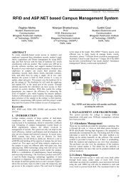
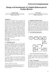
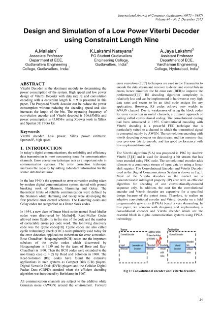
shift register. The Convolutional Encoder <strong>and</strong> <strong>Viterbi</strong> <strong>Decoder</strong><br />
used in the Digital Communications System is shown in Fig:1.<br />
Most <strong>of</strong> the <strong>Viterbi</strong> decoders in the market are a<br />
parameterizable intelligent property (IP) core with an efficient<br />
algorithm for decoding <strong>of</strong> one convolutionally-encoded<br />
sequence only. In addition, the cost for the convolutional<br />
encoder <strong>and</strong> <strong>Viterbi</strong> decoder are expensive for a specified<br />
design because <strong>of</strong> the patent issue. Therefore, to realize an<br />
adaptive convolutional encoder <strong>and</strong> <strong>Viterbi</strong> decoder on a field<br />
programmable gate array (FPGA) board is very dem<strong>and</strong>ing. In<br />
this paper, we concern with designing <strong>and</strong> implementing a<br />
convolutional encoder <strong>and</strong> <strong>Viterbi</strong> decoder which are the<br />
essential block in digital communication systems <strong>using</strong> FPGA<br />
technology.<br />
Fig 1: Convolutional encoder <strong>and</strong> <strong>Viterbi</strong> decoder.<br />
All communication channels are subject to the additive white<br />
Gaussian noise (AWGN) around the environment. Forward<br />
24
International Journal <strong>of</strong> Computer Applications (0975 – 8887)<br />
Volume 84 – No 2, December 2013<br />
2. CONVOLUTIONAL ENCODER<br />
A convolutional code is a type <strong>of</strong> error-correcting code which<br />
differs a lot from block codes[1]. First, the former does not<br />
have code words made up <strong>of</strong> distinct data sections <strong>and</strong> block<br />
sections. Instead, redundant bits are distributed throughout the<br />
coded data. Second, the encoder <strong>of</strong> the former contains<br />
memory <strong>and</strong> the n encoder outputs at any given time unit<br />
depend not only on the k inputs at that time unit but also on m<br />
previous input blocks. Convolutional codes are sometimes<br />
referred as trellis codes. Normally, convolutional encoding is<br />
simple, but decoding is much more difficult.<br />
Convolutional codes are usually characterized by two<br />
parameters <strong>and</strong> the patterns <strong>of</strong> n modulo-2 adders. The two<br />
important parameters are the code rate <strong>and</strong> constraint length.<br />
The code rate (k/n) where the number <strong>of</strong> output bits must equal<br />
or bigger than the input bits (n,k), is expressed as a ratio <strong>of</strong> the<br />
number <strong>of</strong> bits into the Convolutional encoder k to the number<br />
<strong>of</strong> channel symbols output by the Convolutional encoder n in a<br />
given encoder cycle[1]. To convolutionally encode data, start<br />
with m memory registers (flip flop), each holding 1 input bit.<br />
Unless if not fixed, all memory registers start with a value <strong>of</strong><br />
0.Theencoder has n modulo-2 adders, <strong>and</strong> n generator<br />
polynomials, one for each adder. An input bit m1 is fed into the<br />
left most register. Using the generator polynomials <strong>and</strong> the<br />
existing values in the remaining registers, the encoder outputs n<br />
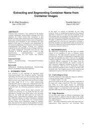
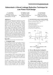
bits. As shown in Fig:2, where we have a general encoder<br />
designed with a code rate (k/n) <strong>of</strong> 1/2 <strong>and</strong> an information<br />
sequence that is being shifted in to the register m <strong>of</strong> 1 bit at a<br />
time. The shift register has a constraint length (K) <strong>of</strong> 3, equal to<br />
the number <strong>of</strong> stages in the register. The output from the<br />
encoder is called code symbols. At initialization all stages in<br />
the encoder shall be initially set to zero. The output <strong>of</strong> the<br />
encoder is determined by the generator polynomial equations.<br />
Since the complexity <strong>of</strong> the encoder increases exponentially<br />
with the constraint length, none <strong>of</strong> the encoders uses more than<br />
a constraint length <strong>of</strong> 9, for practical reasons.<br />
conversation on sequential decoding algorithms is further than<br />
the scope <strong>of</strong> this paper.<br />
<strong>Viterbi</strong> decoding has the advantage that it has a fixed<br />
decoding time[5][6]. It is well suited to hardware decoder<br />
execution. But its computational necessities grow exponentially<br />
as a function <strong>of</strong> the constraint length, so it is generally limited<br />
in practice to constraint lengths <strong>of</strong> K= 9 or less. Stanford<br />
Telecom produces a K= 9 <strong>Viterbi</strong> decoder that operates at rates<br />
up to 96 kbps, <strong>and</strong> a K=7<strong>Viterbi</strong> decoder that operates at up<br />
to 45Mbps.AdvancedWireless Technologies (AWT) <strong>of</strong>fers a<br />
K = 9 <strong>Viterbi</strong> decoder that operates at rates up to 2 Mbps.<br />
For years, convolutional coding with <strong>Viterbi</strong> decoding has been<br />
the predominant FEC technique used in space<br />
communications, particularly in geo stationary satellite<br />
communication networks, such as VSAT (very small<br />
aperture terminal) networks. I think the most common<br />
variant used in VSAT networks is rate 1/2 convolutional<br />
coding <strong>using</strong> a code with a constraint length K= 9. With this<br />
code, you can transmit binary or quaternary phase-shift-keyed<br />
(BPSK or QPSK) signals with at least 5 dB less power than<br />
you'd need without it. That is a reduction in watts <strong>of</strong> more than<br />
a factor <strong>of</strong> three.<br />
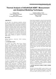
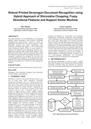
Fig 3: Block diagram <strong>of</strong> <strong>Viterbi</strong> decoder.<br />
4. IMPLEMENTATION OF VITERBI<br />
DECODER<br />
The major tasks in the <strong>Viterbi</strong> decoder process are as follows:<br />
• Branch metric unit<br />
• Add compare -select unit.<br />
• Path metric unit<br />
• Survivor metric unit<br />
Fig.3 shows the proposed <strong>Viterbi</strong> decoder. This section<br />
discusses the different parts <strong>of</strong> the <strong>Viterbi</strong> decoding process[7].<br />
Analog signals are quantized <strong>and</strong> converted into digital signals<br />
in the quantization block. The frame boundaries <strong>of</strong> code words<br />
<strong>and</strong> symbol boundaries were detected by the synchronization<br />
block. We assume that a <strong>Viterbi</strong> decoder receives parallel<br />
successive code symbols, in which the boundaries <strong>of</strong> the<br />
symbols <strong>and</strong> the frames have been identified.<br />
Fig 2: Convolutional encoder with data rate <strong>of</strong> 1/2 <strong>and</strong><br />
constraint length 3.<br />
3. VITERBI DECODING ALGORITHM<br />
<strong>Viterbi</strong> decoding is one <strong>of</strong> two types <strong>of</strong> decoding<br />
algorithms [3]used with convolutional encoding the other<br />
type is sequential decoding. Sequential decoding has the<br />
benefit <strong>of</strong> that it can perform very well with long-constraintlength<br />
convolution codes, but it has a variable decoding time. A<br />
4.1 Branch Metric Unit<br />
Branch metric unit is used to generate branch metrics[4], which<br />
are hamming distances <strong>of</strong> input data from 00, 01, 10 <strong>and</strong> 11.<br />
The BM unit is used to calculate branch metric for all trellis<br />
branches from the input data[5]. We choose absolute difference<br />
as measure for branch metric. These branch metrics are<br />
considered as equaling the weights <strong>of</strong> the branches<br />
4.2 ACS (Add Compare Select) Unit<br />
A new value <strong>of</strong> the state metrics has to be computed at each<br />
time instant. In other words, the state metrics have to be<br />
updated every clock cycle. Because <strong>of</strong> this recursion,<br />
25
International Journal <strong>of</strong> Computer Applications (0975 – 8887)<br />
Volume 84 – No 2, December 2013<br />
pipelining, a common approach to increase the throughput <strong>of</strong><br />
the system, is not applicable. The Add-Compare-Select (ACS)<br />
unit hence is the module that consumes the most power<br />
<strong>and</strong> area.<br />
Since the state metrics are always positive numbers <strong>and</strong><br />
since only positive branch metrics are added to them, the<br />
accumulated metrics would grow indefinitely without<br />
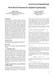
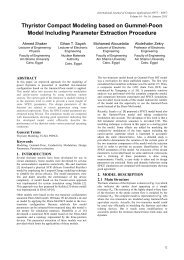
normalization. The operation <strong>of</strong> the ACS unit is shown in Fig.<br />
4. The new branch metrics are added to previous state metrics<br />
to form the c<strong>and</strong>idates for the new state metrics. The<br />
comparison can be done by <strong>using</strong> the subtraction <strong>of</strong> the two<br />
c<strong>and</strong>idate state metrics, <strong>and</strong> the MSB <strong>of</strong> the difference<br />
points to a larger one <strong>of</strong> two.<br />
5.1<strong>Simulation</strong>Waveforms <strong>of</strong> Convolution<br />
Encoder <strong>and</strong> <strong>Viterbi</strong> <strong>Decoder</strong><br />
The <strong>Simulation</strong> Waveform <strong>of</strong> <strong>Viterbi</strong> <strong>Decoder</strong> is shown in<br />
Figure 9 (For Rate ½ <strong>and</strong> K = 9). The simulation is done by<br />
<strong>using</strong> Modelsim <strong>and</strong> the speed <strong>and</strong> resource utilization is<br />
generated <strong>and</strong> synthesized <strong>using</strong> Xilinx Synthesis Tool (XST).<br />
Fig 5: <strong>Simulation</strong> result <strong>of</strong> convolution encoder<br />
Fig 4: ACS Unit.<br />
4.3 Path Metric unit<br />
Memory is required to store the survivor Path Matrix Unit<br />
(PMU)[2]. The word length <strong>of</strong> the memory depends on the<br />
number <strong>of</strong> the ACS sub-blocks used in the design or the total<br />
number <strong>of</strong> states in the decoder or k^2 (where k is the<br />
International Journal <strong>of</strong> Modeling <strong>and</strong> Optimization, Vol. 3,<br />
No. 1, February 2013 16constraint length, 5 in our case), <strong>and</strong><br />
the depth <strong>of</strong> the memory depends on the trellis length. The<br />
memory depth usually should be kept two times the trellis<br />
length or two blocks <strong>of</strong> memory equal to trellis length. We<br />
have for our project k = 5<strong>and</strong> trellis length equal to 32, so the<br />
memory block used is64x16. The memory used is dual port.<br />
One port for writing the data <strong>and</strong> other for reading the data, as<br />
we need to write <strong>and</strong> read the data simultaneously <strong>and</strong> that to<br />
from different addresses. Memory should write data<br />
synchronously but the reading <strong>of</strong> the data should be<br />
asynchronous to keep the latency low or better manage the<br />
synchronous behavior <strong>of</strong> the full system.<br />
4.4 Survivor metric unit<br />
In this the output data is obtained in survivor metric unit<br />
(SMU). In this survivor metric unit two bits obtained the LSB<br />
bits are neglected only the MSB bits are taken as output. So,<br />
smu is output decision unit.<br />
5. SIMULATION AND SYNTHESIS<br />
RESULTS<br />
Synthesis is a process <strong>of</strong> constructing a gate level netlist from a<br />
register transfer level model <strong>of</strong> a circuit described in Verilog<br />
HDL .Increase the design size <strong>and</strong> complexity, as well as<br />
improvement in design synthesis <strong>and</strong> simulation tools, have<br />
made Hardware Description Languages (HDLs) the preferred<br />
design languages <strong>of</strong> most integrated circuit designers. The two<br />
important HDL synthesis <strong>and</strong> simulation languages are Verilog<br />
<strong>and</strong> VHDL. Both have been adopted as IEEE st<strong>and</strong>ards.<br />
In the above simulation waveform the convolution encoder<br />
encoded <strong>and</strong> store the 256 bits in the one half <strong>of</strong> the cycle is<br />
shown in above fig:5.<br />
Fig 6: <strong>Simulation</strong> result <strong>of</strong> viterbi decoder.<br />
In the above simulation waveform the viterbi decoder decoded<br />
the encoded bit stream <strong>and</strong> give the output on the second half<br />
<strong>of</strong> the cycle is shown in above fig:6.<br />
5.2 Device Utilization Report<br />
This synthesis report is generated after the compilation <strong>of</strong><br />
<strong>Design</strong> for the targeted Xilinx SPARTAN 3E based Xc3s400a<br />
FPGA Device. Here, The <strong>Design</strong> unit is not implemented on<br />
targeted FPGA Device. This report contains about Timing <strong>and</strong><br />
power summary.<br />
26
International Journal <strong>of</strong> Computer Applications (0975 – 8887)<br />
Volume 84 – No 2, December 2013<br />
6. COMPARISON OF RESULTS<br />
TABLE 1<br />
Parameters Existing system Proposed system<br />
Data rate ¾ 1/2<br />
Constraint<br />
length<br />
No <strong>of</strong> bits<br />
stored for<br />
each cycle<br />
Frequency<br />
<strong>Power</strong><br />
7 9<br />
2^(7-1)=64 bits<br />
446.4MHz<br />
20.069mW<br />
2^(9-1)=256 bits<br />
306.65MHz<br />
45.01mW<br />
In this paper final result the data rate is decrease to 1/2 <strong>and</strong> the<br />
constraint length increases to 9, so at the output number <strong>of</strong> bits<br />
stored for each cycle increases to 256 bits. The frequency<br />
decreases to 306.65 MHz <strong>and</strong> the power consumption increases<br />
to 45.01mW.But when compared with the previous system the<br />
256 bits transmission power increases to 4times that is 81mW<br />
used but our proposed system only 45.01mW consumed so<br />
power reduced to 50%.<br />
7. CONCLUSIONS<br />
In this Paper Resource optimized <strong>Viterbi</strong> <strong>Decoder</strong> with rate 1/2<br />
<strong>and</strong> constraint length 9 has been proposed. The proposed<br />
<strong>Viterbi</strong> <strong>Decoder</strong> has been designed with Verilog <strong>using</strong> trace<br />
back method. The designed <strong>Viterbi</strong> <strong>Decoder</strong> has been<br />
simulated <strong>using</strong> Modelsim simulator <strong>and</strong> synthesized with<br />
Xilinx ISE. The simulated <strong>and</strong> synthesized results show that<br />
proposed design can work at an estimated frequency <strong>of</strong> 306.65<br />
MHz for constraint length 9 respectively by <strong>using</strong> considerable<br />
less resources <strong>of</strong> target FPGA device SPARTAN 3E. This<br />
Paper also shows impact <strong>of</strong> constraint length on the<br />
performance. The comparative analysis result shows that as<br />
constraint length increases VLSI hardware complexity<br />
increases <strong>and</strong> Max. Frequency decreases <strong>and</strong> constraint length<br />
increases bit error rate decreases.<br />
8. REFERENCES<br />
[1] A. J. <strong>Viterbi</strong>, ―Error bounds for convolutional<br />
codes <strong>and</strong> an asymptotically optimum<br />
decodingalgorithm,‖ IEEE Transactions on Information<br />
Theory, vol. 13, no. 2, pp. 260–269, April 1967.<br />
[2] G. Fettweis <strong>and</strong> H. Meyr., ―Parallel <strong>Viterbi</strong> decoding by<br />
breaking the compare select feedbackbottleneck,‖<br />
Communications, vol. 201, no.88, 1988.<br />
[3] J. He, Z. Wang, <strong>and</strong> H. Liu, “An efficient 4-D 8PSKTCM<br />
decoder architecture,” IEEE Trans. Very Large Scale<br />
Integr. (VLSI) Syst., vol.18, no. 5, pp. 808–817, May<br />
2010.<br />
[4] Jinjin He, Huaping Liu, Zhongfeng Wang, Xinming<br />
Huang, <strong>and</strong> Kai Zhang “High-Speed <strong>Low</strong>-<strong>Power</strong><br />
<strong>Viterbi</strong><strong>Decoder</strong> <strong>Design</strong> for TCM <strong>Decoder</strong>s”IEEE<br />
Transactions on very large scale integration (VLSI)<br />
systems, vol.20,no.4,april 2012.<br />
[5] J. Jin <strong>and</strong> C.-Y. Tsui, “<strong>Low</strong>-power limited-search parallel<br />
state viterbi decoder implementation based onscarece state<br />
transition,” IEEE Trans.Very Large Scale Integr. (VLSI)<br />
Syst., vol. 15, no. 11, pp. 1172–1176,Oct. 2007.<br />
[6] M. Boo, F. Arguello, J. D. Bruguera, R. Doallo, <strong>and</strong><br />
E. L. Zapata., ―High-performance VLSI architecture for<br />
the <strong>Viterbi</strong> algorithm,‖ IEEE Trans. on communications,<br />
vol. 45, no. 2, pp.168–176, 1997.<br />
[7] P.J. Black <strong>and</strong> T. H. Meng, ―A 1-Gb/s, four-state, sliding<br />
block <strong>Viterbi</strong> decoder,‖ IEEE Journal <strong>of</strong> Solid-State<br />
Circuits, vol. 32 no. 6, pp.797–805, 1997.<br />
[8] R. A. Abdallah <strong>and</strong> N. R. Shanbhag, “Error-resilient lowpower<br />
viterbi decoder architectures,”IEEE Trans. Signal<br />
Process., vol. 57, no. 12,pp. 4906–4917, Dec. 2009.<br />
[9] Russell Henning ,<strong>and</strong> ChaitaliChakrabarti“An Approach<br />
for Adaptively Approximating the<strong>Viterbi</strong> Algorithm to<br />
Reduce <strong>Power</strong> ConsumptionWhile Decoding<br />
Convolutional Codes” IEEE Trans. On Signal Processing,<br />
Vol. 52, No. 5, May 2004<br />
[10] V. Tomas, ―Decoding <strong>of</strong> convolutional codes over<br />
the erasure channel,‖ IEEE Trans. on Information<br />
Theory, vol. 58,no. 1, pp. 90-108, Jan. 2012.<br />
9. AUTHORS BIOGRAPHY<br />
A.Mallaiah received the M.E degree in Electronic<br />
Instrumentation from Andhra University, Visakhapatnam in<br />
2004, B.Tech degree in Electronics <strong>and</strong> Communication<br />
Engineering from R.V.R & J.C College <strong>of</strong> Engineering, Guntur<br />
in 2002. He is pursuing Ph.D from JNTUA, Anantapuramu. He<br />
is Associate Pr<strong>of</strong>essor, Department <strong>of</strong> Electronics <strong>and</strong><br />
Communication Engineering at Gudlavalleru Engineering<br />
College, Gudlavalleru. He has a total teaching experience <strong>of</strong> 10<br />
years. He has guided <strong>and</strong> co-guided 13 P.G students. His<br />
research areas include Embedded Systems, Molecular<br />
Electronics, Digital Signal Processing <strong>and</strong> Digital Image<br />
Processing.<br />
K.LakshmiNarayana obtained his Bachelor’s Degree from Sri<br />
Sunflower College <strong>of</strong> Engineering&Technology, lankapalli in<br />
2010. His Areas <strong>of</strong> interest in Digital Signal Processors <strong>and</strong><br />
Digital System <strong>Design</strong>, Embedded System<strong>Design</strong>, <strong>Low</strong> <strong>Power</strong><br />
VLSI <strong>Design</strong>. Presently he is doing M.Tech Digital Electronics<br />
<strong>and</strong> Communication Systems at Dept.<strong>of</strong> ECE, Gudlavalleru<br />
Engineering College, Gudlavalleru, India.<br />
A.Jaya Lakshmi received the M.E<br />
degree in Communication <strong>and</strong> Signal Processing<br />
fromVRSiddhartha engineering college, Vijayawada in 2010,<br />
B.Tech degree in Electronics <strong>and</strong> Communication Engineering<br />
fromNimra College <strong>of</strong> engineering <strong>and</strong> technology,Vijayawada<br />
in 2005.She is Assistant Pr<strong>of</strong>essor, Department <strong>of</strong> Electronics<br />
<strong>and</strong> Communication Engineering atVardhaman College <strong>of</strong><br />
engineering, Hyderabad. . She has a total teaching experience<br />
<strong>of</strong> 7 years. Her research areas include Embedded Systems,<br />
Digital Signal Processing <strong>and</strong> Digital Image Processing.<br />
IJCA TM : www.ijcaonline.org<br />
27