resolver decoder specifications - Steven Engineering
resolver decoder specifications - Steven Engineering
resolver decoder specifications - Steven Engineering

Create successful ePaper yourself
Turn your PDF publications into a flip-book with our unique Google optimized e-Paper software.
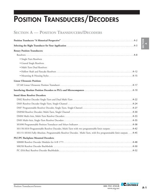
POSITION TRANSDUCERS/DECODERS<br />
SECTION A — POSITION TRANSDUCERS/DECODERS<br />
Position Tranducers “A Historical Perspective” . . . . . . . . . . . . . . . . . . . . . . . . . . . . . . . . . . . . . . . . . . . . . . . . . . . . . . . . A-2<br />
Selecting the Right Transducer for Your Application . . . . . . . . . . . . . . . . . . . . . . . . . . . . . . . . . . . . . . . . . . . . . . . . . . . . A-3<br />
Rotary Position Transducers:<br />
Resolvers. . . . . . . . . . . . . . . . . . . . . . . . . . . . . . . . . . . . . . . . . . . . . . . . . . . . . . . . . . . . . . . . . . . . . . . . . . . . . . . . . . . . A-8<br />
• Single-Turn Resolvers<br />
• Geared Single Resolvers<br />
• Multi-Turn Dual Resolvers<br />
• Hollow Shaft and Pancake Resolvers . . . . . . . . . . . . . . . . . . . . . . . . . . . . . . . . . . . . . . . . . . . . . . . . . . . . . . . . . . . A-12<br />
• Mounting & Housing Styles . . . . . . . . . . . . . . . . . . . . . . . . . . . . . . . . . . . . . . . . . . . . . . . . . . . . . . . . . . . . . . . . . A-15<br />
SECTION<br />
A<br />
Linear Ultrasonic Position:<br />
LT140 Linear Ultrasonic Position Transducer . . . . . . . . . . . . . . . . . . . . . . . . . . . . . . . . . . . . . . . . . . . . . . . . . . . . . . . . A-17<br />
Interfacing Absolute Position Decoders to PLCs and Microcomputers . . . . . . . . . . . . . . . . . . . . . . . . . . . . . . . . . . . . . A-19<br />
Stand Alone Resolver Decoders:<br />
DM2 Resolver Decoder Single-Turn and Dual Multi-Turn . . . . . . . . . . . . . . . . . . . . . . . . . . . . . . . . . . . . . . . . . . . . . . A-22<br />
DM5 Resolver Decoder Single-Turn, Single-Channel . . . . . . . . . . . . . . . . . . . . . . . . . . . . . . . . . . . . . . . . . . . . . . . . . . A-24<br />
DM7 Programmable Resolver Decoder, Single-Turn, Single-Channel. . . . . . . . . . . . . . . . . . . . . . . . . . . . . . . . . . . . . . . A-27<br />
DM960 Resolver Decoder: Multi-Turn, Single Channel . . . . . . . . . . . . . . . . . . . . . . . . . . . . . . . . . . . . . . . . . . . . . . . . A-30<br />
DMM Multi-Axis, Multi-Turn Resolver Decoders. . . . . . . . . . . . . . . . . . . . . . . . . . . . . . . . . . . . . . . . . . . . . . . . . . . . . A-33<br />
DMS Multi-Axis, Single-Turn Resolver Decoders . . . . . . . . . . . . . . . . . . . . . . . . . . . . . . . . . . . . . . . . . . . . . . . . . . . . . A-35<br />
M1890 Programmable Position Transducer and Selsyn Indicator . . . . . . . . . . . . . . . . . . . . . . . . . . . . . . . . . . . . . . . . . . A-38<br />
M1150-M10 Programmable Resolver Decoder, Multi-Turn with two programmable limit outputs . . . . . . . . . . . . . . . . . A-42<br />
M1151-M10A Fully-Absolute, Programmable Resolver Decoder, Multi-Turn, with five programmable limit outputs . . . A-45<br />
PLC/PC Backplane Mounted Decoders:<br />
M8000 Resolver Decoder Modules for A-B 1771 . . . . . . . . . . . . . . . . . . . . . . . . . . . . . . . . . . . . . . . . . . . . . . . . . . . . . A-48<br />
M8350 Resolver Decoder BusModule . . . . . . . . . . . . . . . . . . . . . . . . . . . . . . . . . . . . . . . . . . . . . . . . . . . . . . . . . . . . . A-50<br />
PC (ISA-Bus) Resolver Decoder BusModule . . . . . . . . . . . . . . . . . . . . . . . . . . . . . . . . . . . . . . . . . . . . . . . . . . . . . . . . . A-52<br />
Position Transducers/Sensors<br />
800-TEC-ENGR<br />
www.avg.net<br />
A-1
POSITION TRANSDUCERS<br />
A HISTORICAL PERSPECTIVE<br />
Since its inception in 1975 Autotech Controls division of<br />
AVG Automation has been in the forefront of developing<br />
<strong>resolver</strong> based technology for the industry. Through continuous<br />
innovation and by virtue of its vertical integration AVG<br />
Automation is able to bring to you the ruggedness and noise<br />
immunity of <strong>resolver</strong> based technology for the cost of optical<br />
encoders. Over half a million AVG <strong>resolver</strong>s are in use all over<br />
the world to provide position/motion feedback to such controls<br />
as PLCs, CNCs, computer based controls and definite<br />
purpose OEM controls.<br />
Back in 1985, AVG Automation revolutionized the encoder<br />
market by introducing the Digisolver; industry's first <strong>resolver</strong><br />
based digital encoder that combined the ruggedness of a<br />
<strong>resolver</strong> with the reliability of solid-state circuitry.<br />
In late 80's Autotech introduced the concept of <strong>resolver</strong><br />
<strong>decoder</strong> module that plugs directly into the PLCs eliminating<br />
the need of stand alone <strong>decoder</strong> module. In the world of proprietary<br />
PLCs and racks, these modules called BusModules<br />
provide the only "Universal" solution. These modules are universal<br />
as the same module can be used in any of the supported<br />
PLC racks offering a common user interface (for a function)<br />
across different PLCs.<br />
Today AVG Automation offers the broadest line of <strong>resolver</strong><br />
based encoders in the industry:<br />
❐ 4" housing; 5/8" shaft<br />
❐ 2.5" housing; 3/8" shaft<br />
❐ 2.5" housing; 1/4" shaft<br />
❐ 1.1" housing<br />
❐ Hollow shaft<br />
❐ Pancake <strong>resolver</strong>s<br />
❐ Single turn<br />
❐ Single turn geared<br />
❐ Multi-turn geared<br />
❐ NEMA4/NEMA4X/NEMA13/NEMA6P<br />
❐ Class 1, Div 1, groups B, C and D<br />
❐ FM approved<br />
❐ Intrinsically safe<br />
❐ Explosion proof<br />
❐ Binary/BCD/Gray Code outputs<br />
❐ PC handshake<br />
❐ Analog Velocity<br />
❐ PLC back plane mounted <strong>resolver</strong> encoders for:<br />
– AB 1771<br />
– Modicon 800<br />
– Modicon 984-A120<br />
– GE 9070<br />
– TI 505<br />
❐ Network <strong>resolver</strong>s:<br />
– DeviceNet<br />
– Profibus<br />
– Interbus<br />
A-2<br />
800-TEC-ENGR<br />
www.avg.net<br />
Position Transducers/Sensors
SELECTING THE RIGHT POSITION<br />
TRANSDUCER FOR YOUR APPLICATION<br />
Even though the position transducers are the most critical<br />
parts in a motion control system, many times they are left<br />
towards the end to be designed in. A control design engineer<br />
can save himself a lot of headache by considering the transducer<br />
features and trade-offs at the beginning of the project. The<br />
following discusses various types of position transducers and<br />
the factors to consider when making a selection.<br />
Many industrial control systems need position and speed feedback.<br />
Until a few years ago, tachometers provided the speed<br />
and limit switches provided the position information.<br />
However, with new requirements of higher accuracies, faster<br />
machine speeds, and greater reliability combined with technological<br />
breakthrough in the field of electronics, a variety of<br />
new designs of position transducers emerged. These transducers<br />
made it possible to know the machine position at all times,<br />
rather than waiting for a limit switch to give position indication<br />
at a predetermined point. This permitted faster machine<br />
operation and increased throughputs.<br />
In the initial stages, the position transducers consisted of<br />
potentiometers, brush encoders, magnetic encoders and rarely<br />
optical encoders and <strong>resolver</strong>s. Each device had certain limitations.<br />
The potentiometers and magnetic encoders had limited<br />
resolution. The brush encoders required frequent maintenance.<br />
The optical encoders used incandescent lamps, which were<br />
large in size and had limited life expectancy. The <strong>resolver</strong>s<br />
could offer better resolution and accuracy, but were very<br />
expensive due to the decoding electronics required.<br />
The recent technological developments have brought some<br />
improvements in the initial models. Today optical encoders and<br />
<strong>resolver</strong>s are more commonly used in industry. The magnetic<br />
and magnetoresistive encoders find applications less frequently.<br />
We will focus on two of the more popular types of position<br />
transducers: Optical Encoders and Resolvers.<br />
Optical encoders and <strong>resolver</strong>s are available in two major categories:<br />
Absolute and Incremental. The incremental encoder,<br />
when it rotates, generates pulses, which are counted to give<br />
position information relative to a known point, whereas an<br />
absolute encoder provides a unique value at each position and<br />
retains actual shaft position even if power fails. Multi-turn<br />
units with built-in gear trains are available for linear application<br />
where it takes several revolutions of the encoder shaft to<br />
complete one machine cycle.<br />
Optical Encoders<br />
The Optical Encoders typically consist of a rotating and a stationary<br />
member. The rotor is usually a metal, glass, or a plastic<br />
disc mounted on the encoder shaft. The disc has some kind of<br />
optical pattern, which is electronically decoded to generate<br />
position information. The rotor disc in absolute optical<br />
encoder uses opaque and transparent segments arranged in a<br />
gray-code pattern. The stator has corresponding pairs of LEDs<br />
and phototransistors arranged so that the LED light shines<br />
through the transparent sections of the rotor disc and received<br />
by phototransistors on the other side. See figure below.<br />
Depending upon the shaft position, the phototransistor output<br />
is modulated in a gray-code pattern, which can be converted<br />
internally to binary or BCD. Typically CMOS, TTL-, PNP-,<br />
and NPN-type outputs with 8- or 10-bit Gray-code, binary, or<br />
BCD formats are available.<br />
The incremental optical encoders (figure 1) use a much simpler<br />
disc pattern. This slotted rotor disc alternately interrupts<br />
the light beam between the LED transmitter-receiver pair and<br />
thus produces a pulse output. The number of pulses depends<br />
on the number of slots on the disc. The pulses are then fed to<br />
a counter, where they are counted to give position information.<br />
The pulse rate indicates shaft speed. An additional LED<br />
pair can also determine the direction of rotation. Some modules<br />
also provide a marker pulse output, which is generated<br />
once every revolution at a fixed shaft position and can be used<br />
to mark a zero reference point. Many different pulse configurations<br />
are available, but the most commonly known are the<br />
quadrature encoders, where two square wave pulses 90 degrees<br />
apart from each other are generated.<br />
SECTION<br />
A<br />
Position Transducers/Sensors<br />
800-TEC-ENGR<br />
www.avg.net<br />
A-3
As the shaft rotates, the output voltages of the stator<br />
windings vary as the sine and cosine of the<br />
shaft angle. See figure 2.<br />
The two induced stator voltages are a measure of<br />
the shaft angle and are converted to a digital signal<br />
in <strong>resolver</strong>-to-digital <strong>decoder</strong>. Among various<br />
R/D decoding methods available, the two most<br />
commonly used are:<br />
❐ Ratiometric Tracking Converter<br />
❐ Phase Method Converter.<br />
(Figure 1)<br />
Resolver Encoders<br />
Resolvers are essentially a rotary transformer, having one rotor<br />
winding and two stator windings. The stator windings are located<br />
90 degrees apart. Either rotor or stator winding can be used<br />
as primary. Typically, the rotor winding is driven by a reference<br />
voltage at a frequency ranging from 400 Hz to several KHz.<br />
Ratiometric Tracking Converter<br />
(A typical block diagram for a Ratiometric Tracking<br />
Converter is shown in figure 3.)<br />
The circuit features a Type II servo-loop that comprises of<br />
sine/cosine multiplier and an error amplifier together with<br />
phase sensitive demodulator, error processor, voltage controlled<br />
oscillator (VCO) and an up/down counter. Since the VCO is<br />
controlled by an error integrator, greater the lag between the<br />
actual shaft angle and the digital angle in the counter, faster<br />
will the counter be called upon to "catch-up" or "track" and<br />
eliminate the error.<br />
The information produced by this type of converter is always<br />
"fresh", being continually updated and always available at the<br />
output. As an added bonus, additional outputs, such as, an<br />
analog output proportional to the shaft RPM to eliminate<br />
external tachometers and a busy signal pulse for incremental<br />
pulse applications, are also available. The basis of determining<br />
the shaft angle in a ratiometric converter is the ratio between<br />
the two stator signals:<br />
From this relationship it can be noted that the angle is no longer<br />
a function of the induced rotor voltage Vr, but rather the ratio of<br />
V S1 and V S2 . Therefore, variations in the rotor voltage Vr, frequency<br />
and temperature are no longer factors in a ratiometric<br />
converter. This results in a highly accurate and repeatable <strong>resolver</strong>to-digital<br />
converter.<br />
(Figure 2)<br />
A-4<br />
800-TEC-ENGR<br />
www.avg.net<br />
Position Transducers/Sensors
SECTION<br />
A<br />
(Figure 3)<br />
Phase Method Decoder<br />
(A block diagram of a typical Phase Method Decoder is shown in<br />
figure 4.)<br />
The principle of operation is based on the fact that the phase<br />
difference between reference voltage and the voltage induced<br />
in the rotor is a direct measure of the shaft position. The stator<br />
windings are excited by two 90° phase-shifted voltages generated<br />
by a sine/cosine generator. The counter is preset to zero at<br />
zero crossing of the reference voltage and latched at zero crossing<br />
of the rotor voltage, and the difference between preset and<br />
latch gives the shaft angle. The phase method <strong>decoder</strong>s do not<br />
have the environmental immunity of the ratiometric converters.<br />
The trade-off is the relatively lesser cost of the phase<br />
method <strong>decoder</strong>s.<br />
The output of R/D converters can be offset, displayed and<br />
synchronized to interface with programmable controllers.<br />
The ratiometric <strong>decoder</strong>, though hooked-up to a simple singleturn<br />
<strong>resolver</strong>, can be programmed to operate in single-turn or<br />
multi-turn mode. Simple front panel set-up of counts per turn<br />
eliminates any mechanical gear trains. With program stored in<br />
non-volatile EEROM memory, it is presettable, prescalable,<br />
and still absolute (over half a turn). Parallel BCD output with<br />
built-in PC-Handshake and serial link facilitates direct interface<br />
to programmable controllers and computers.<br />
Position Transducers/Sensors<br />
800-TEC-ENGR<br />
www.avg.net<br />
A-5
(Figure 4)<br />
Factors to be considered for<br />
Selection of Position Transducers<br />
For an efficient control system, the right selection of a position<br />
transducer is as important as the signal processing itself. Here<br />
are some of the features and trade-Off to be considered to<br />
match the position transducer to your application.<br />
Optical Encoder vs. Resolver<br />
This decision is primarily based on the operating environment.<br />
The environmental integrity of a brushless <strong>resolver</strong> is<br />
unchallenged. Being simple rotary transformers, the <strong>resolver</strong>s<br />
can take much more abuse than optical encoders and exhibit<br />
no significant wear or aging. Especially, if the operating temperature<br />
is below freezing or above 150 °F, there is no other<br />
choice, but to go for <strong>resolver</strong>s. Operating temperature range of<br />
<strong>resolver</strong>s is typically between -67 °F to +248 °F. In extremely<br />
hostile environment such as continuous mechanical shock and<br />
vibrations, humidity, oil mist, coolants and solvents, <strong>resolver</strong> is<br />
the best choice.<br />
Incremental vs. Absolute<br />
Can you afford to lose position in case of power failure? If the<br />
answer is no, then you must use an absolute encoder. An incremental<br />
encoder simply generates pulses proportional to the<br />
position, whereas an absolute encoder generates a unique code<br />
for each position. After a power outage, with an absolute<br />
encoder the machine operation will pick up from where it had<br />
left off. In an incremental encoder the pulses generated are<br />
counted in a counter and at power loss it will lose the count<br />
and consequently you will have to home the machine before<br />
you can start the operation. Also, an incremental encoder is<br />
generally more susceptible to electrical noise. The absolute<br />
encoders are more expensive than the incremental encoders are.<br />
Therefore, a price/feature trade-off may be worth considering.<br />
A-6<br />
800-TEC-ENGR<br />
www.avg.net<br />
Position Transducers/Sensors
Single-Turn vs. Multi-Turn<br />
In a single-turn encoder, the encoder shaft makes one revolution<br />
for one complete cycle of machine operation, where as in<br />
a multi-turn application, the encoder shaft makes more than<br />
one revolutions to complete one machine cycle. Angular rotation<br />
of a crankshaft in a punch press or rotary indexing table<br />
are typical examples of single-turn applications. In linear positioning,<br />
where the encoder shaft makes several turns to complete<br />
total travel, a multi-turn encoder will be required.<br />
Absolute multi-turn encoders and <strong>resolver</strong>s are available with<br />
various built-in gear ratios. Incremental encoders can be used<br />
both in single-turn and multi-turn applications.<br />
Ratiometric vs. Phase Method Decoder<br />
The ratiometric converters can track the shaft movements<br />
faster and can be mounted at a greater distance from <strong>resolver</strong>s<br />
as compared to phase method <strong>decoder</strong>s. They are also more<br />
immune to electrical noise and variations of voltage, frequency,<br />
temperature, etc. Due to the more complex circuitry involved,<br />
the ratiometric converters are usually more expensive than<br />
phase method <strong>decoder</strong>s. In general, for more reliable operation,<br />
the ratiometric converter should be used. In some applications,<br />
where wiring run is short and well shielded, system<br />
speed is slow or slow reacting outputs like electromechanical<br />
relays are used and the installation is relatively free of electrical<br />
noise, the phase method <strong>decoder</strong> may be considered for a cost<br />
effective design.<br />
Built-in vs. Remote Decoder<br />
Usually, <strong>resolver</strong>-to-digital <strong>decoder</strong>s are housed in a separate<br />
enclosure, but <strong>resolver</strong>s with built-in <strong>decoder</strong>s are also available.<br />
The units with <strong>decoder</strong> circuitry packaged inside a<br />
<strong>resolver</strong>-housing combine the ruggedness of a <strong>resolver</strong> with<br />
simplicity of an optical encoder. However, due to the electronics<br />
present in the same housing, the operating temperature<br />
range is considerably reduced as compared to a <strong>resolver</strong> with<br />
separate <strong>decoder</strong>.<br />
The foregoing discussion is helpful in determining as to what<br />
type of transducer will be suitable for a particular application.<br />
But before one can finalize a transducer selection, one needs to<br />
obtain additional mechanical and electrical requirements of the<br />
system. Mechanical parameters to be determined are housing<br />
size, shaft size and loading requirements, mounting style,<br />
NEMA or explosion proof rating needed and system resolution.<br />
Electrical requirements are the power supply voltage and current,<br />
output type (TTL, CMOS, sinking, sourcing, etc), Analog<br />
or Digital outputs, output format (BCD, Binary, or Grey) etc.<br />
SECTION<br />
A<br />
Position Transducers/Sensors<br />
800-TEC-ENGR<br />
www.avg.net<br />
A-7
ROTARY POSITION TRANSDUCERS<br />
ABSOLUTE POSITION BRUSHLESS RESOLVERS:<br />
Single-Turn, Geared Single-Turn and Dual<br />
(Multi-turn) <strong>resolver</strong>s<br />
◆ Absolute shaft position<br />
◆ No internal electronics<br />
◆ Brushless <strong>resolver</strong><br />
◆ High-resistance to shock and vibrations<br />
◆ NEMA 13 housing provides protection against<br />
water, mist, oil, and dust<br />
◆ Broad temperature range, -67 °F to 248 °F (-55 °C to<br />
120 °C)<br />
◆ Remote ratiometric <strong>resolver</strong> <strong>decoder</strong> provides<br />
highly noise-immune encoder<br />
◆ Choice of heavy-duty, medium-duty and explosionproof<br />
FM-approved housings<br />
RESOLVERS—RUGGED AND RELIABLE<br />
The <strong>resolver</strong> is a highly accurate and highly dependable device<br />
for absolute position shaft encoding. Resolvers have a reliable<br />
track record of applications in aerospace, military, and industry,<br />
where they have been used for decades for position sensing.<br />
Some of the common applications are radar antenna position<br />
sensing, missile guidance systems, NC machine position<br />
feedback, automotive stamping presses, 2-piece-can manufacturing<br />
presses and packaging machines. The <strong>resolver</strong> is<br />
designed to operate reliably under extremely hostile environments<br />
such as continuous mechanical shock, vibration,<br />
extreme temperature and humidity changes, oil mist, coolants,<br />
and solvents. The <strong>resolver</strong> is a passive transducer. It is a brushless<br />
rotary transformer with one rotor and two stator windings.<br />
The stator windings are electrically 90° out-of-phase with each<br />
other. As the shaft rotates, the relative position of the rotor<br />
and the stator windings change. Either the rotor or the two<br />
stator windings together can be used as the primary of the<br />
rotary transformer and the secondary will then produce an<br />
analog-voltage corresponding to the shaft position.<br />
RL100 Resolver—The Workhorse of the<br />
Industry<br />
AVG Automation's model RL100 <strong>resolver</strong> is the most rugged<br />
<strong>resolver</strong> in the industry today. AVG Automation has over<br />
25,000 of these <strong>resolver</strong>s operating with extreme reliability in<br />
highly demanding applications in automotive, can-manufacturing<br />
and packing industries. Rugged, industrial housing,<br />
heavy-duty, double-row, ball bearing and an internal flexible<br />
coupling lend to an extremely reliable design.<br />
Rugged enclosure for<br />
industrial application<br />
Shaft seal against<br />
oil and water, etc.<br />
Size 11 <strong>resolver</strong><br />
Flexible coupling<br />
for isolation of<br />
shock and vibration<br />
A-8<br />
800-TEC-ENGR<br />
www.avg.net<br />
Position Transducers/Sensors
Built-In Gear Train for Multi-Turn Application<br />
Various <strong>resolver</strong> models from AVG Automation are available<br />
with a built-in precision gear train. The <strong>resolver</strong> makes one<br />
turn for many turns (see How to Order for gear ratios available)<br />
of the input shaft.<br />
Explosion-Proof, FM-Approved<br />
AVG Automation's series E8R <strong>resolver</strong> has FM approved,<br />
explosion-proof housing and meets the requirements as per<br />
Division 1, Class 1, Groups B, C, and D.<br />
Dual-Resolvers for Multi-Turn Application<br />
A multi-turn <strong>resolver</strong> consists of two <strong>resolver</strong>s coupled to each<br />
other through a gear train. One of the <strong>resolver</strong>s, called the fine<br />
<strong>resolver</strong>, is coupled to the machine shaft in such a way that it<br />
turns at the same rpm as the machine, while the other <strong>resolver</strong>,<br />
called the coarse <strong>resolver</strong>, is geared down by the gear ratio used.<br />
As the shaft of the multi-turn <strong>resolver</strong> turns with the machine<br />
movement, the coarse <strong>resolver</strong> keeps track of the number of<br />
revolutions and the fine <strong>resolver</strong> keeps track of the shaft position<br />
in each revolution. Thus, the combination of the two<br />
<strong>resolver</strong>-signals gives the absolute machine position. The gear<br />
train uses an antibacklash gear to eliminate backlash errors.<br />
SECTION<br />
A<br />
Electrical:<br />
Frequency: 2250 Hz Rotor Impedance with stator open circuit Zro: 180 + j256 ohms<br />
Input Volatage: 1.88 V Input Current: 6 mA<br />
DC Resistance (Rotor): 18.3 ohms Input Power: 6.5 mW<br />
Output Voltage (Stator): 2.63 V ±5% Transformation Ratio: 1.400:1<br />
Resolver<br />
Housing<br />
Max. Starting Torque<br />
oz. in. @ 77 °F:<br />
(gm/cm @ 25 °C):<br />
Moment of Inertia<br />
(gm/cm2):<br />
SAC-RL100<br />
SAC-RL210<br />
Size 40<br />
4.0" dia.(101.6 mm)<br />
8<br />
(576.1)<br />
Mechanical:<br />
E8R-RL101<br />
E8R-RL210-xxxMC<br />
Size 40 explosion-proof<br />
4.0" dia. (101.6 mm)<br />
8<br />
(576.1)<br />
E7R-RL101<br />
Size 25<br />
2.5" dia. (63.5 mm)<br />
5<br />
(360.04)<br />
SAC-RL101<br />
Size 11<br />
1.1" dia. (27.94 mm)<br />
0.07<br />
(5.04)<br />
45 45 45 3.3<br />
Max. Slew Speed: (RPM) 5000 5000 5000 3600<br />
Shaft Size: 5/8" (15.88 mm) 5/8" (15.88 mm) 3/8" (9.53 mm) 0.120" (3.05 mm)<br />
Max. Shaft Loading<br />
Axial :<br />
Radial:<br />
Bearing Life at Max.<br />
Mfr. Spec. (Rev.)<br />
50 lb. (22.68 kg)<br />
100 lb. (45.36 kg)<br />
50 lb. (22.68 kg)<br />
100 lb. (45.36 kg)<br />
40 lb. (18.14 kg)<br />
36 lb. (16.33 kg)<br />
0.3 lb.<br />
0.7 lb.(0.32 kg)<br />
2 x 10 9 2 x 10 9 2 x 10 8 2 x 10 9<br />
Approx. Weight: 6 lb. (2.72 kg) 8 lb. (3.62 kg) 1 lb. (0.45 kg) 0.25 lb. (0.11 kg)<br />
Environmental<br />
Shock: 200 g for 11 ms 50 g for 11 ms<br />
Vibration: 20 g to 2000 Hz 15 g to 2000 Hz<br />
Temperature:<br />
Operating:<br />
-67 °F to +248 °F (-55 °C to +120 °C)<br />
Storage:<br />
-85 °F to + 302 °F (-65 °C to +150 °C)<br />
Enclosure: NEMA 13 NEMA 4X (Div. I, Class 1, Groups B, C, and D) NEMA 13 NEMA 1<br />
Position Transducers/Sensors<br />
800-TEC-ENGR<br />
www.avg.net<br />
A-9
MOUNTING<br />
Autotech <strong>resolver</strong>s are designed to operate reliable under<br />
extremely hostile environments, such as: continuous mechanical<br />
shock, vibration, extreme temperature and humidity<br />
changes, oil mist, coolant and solvents. Still ordinary precautions<br />
to prevent damage to bearings of any rotation device<br />
should be followed to prolong their life.<br />
1. It is recommended that the Autotech encoder mounting<br />
bracket (MMB-EM359-010) be used, wherever possible, for<br />
size 40 <strong>resolver</strong>s.<br />
The servo-mount <strong>resolver</strong>s may be mounted either with traditional<br />
servo-clamps or through the four threaded mounting<br />
holes on the face of the <strong>resolver</strong>.<br />
The flange-mount <strong>resolver</strong>s are mounted using four mounting<br />
holes in the square flange.<br />
2. If the <strong>resolver</strong> is to be axially shaft driven, be sure that the<br />
shafts are aligned. Misaligned shafts can destroy <strong>resolver</strong><br />
bearings.<br />
3. If a pulley, coupling or sprocket is mounted to the <strong>resolver</strong><br />
shaft, DO NOT hammer or press on the shaft. DO NOT<br />
force fit anything on to or off of the <strong>resolver</strong> shaft.<br />
4. If the <strong>resolver</strong> is belt-driven or chain-driven, DO NOT<br />
OVERTIGHTEN the drive belt or chain. Too much side<br />
loading (radial) can destroy the <strong>resolver</strong> bearings. Side loading<br />
is not allowed for E6R and RL101 (size 11) <strong>resolver</strong>s.<br />
5. To maintain the NEMA 13 rating of the <strong>resolver</strong>, the following<br />
precautions must be taken: a) sealing compound<br />
must be used when fitting the conduit pipe; b) the bearing<br />
seal must be checked once every six months and replaced if<br />
necessary. Lubricating the bearing seal periodically prolongs<br />
its life.<br />
6. Zero Reference: For most <strong>resolver</strong> types, the approximately<br />
zero reference may be located by aligning the shafts as<br />
shown in the figures below.<br />
CAUTION:<br />
RL101 (size 11) <strong>resolver</strong>s must be coupled to an external shaft<br />
using a flexible coupling. See “How to Order” page.<br />
Zero Reference-Size 40 <strong>resolver</strong>s<br />
(SAC-RL100, E8R and SAC-RL210)<br />
Zero Reference-Size 25 <strong>resolver</strong>s<br />
(E7R)<br />
Servo Mount<br />
Flange Mount<br />
Size 40 <strong>resolver</strong>s are at approximately zero when the shaft<br />
key way is aligned with mounting hole and conduit fitting.<br />
Servo mount <strong>resolver</strong>s: Align shaft keyway with the face plate<br />
retaining screw which is in line with a mounting hole.<br />
Flange mount <strong>resolver</strong>: Align shaft keyway with the face plate<br />
retaining screw that lies midway between two mounting holes.<br />
A-10<br />
800-TEC-ENGR<br />
www.avg.net<br />
Position Transducers/Sensors
MOUNTING SPECIFICATIONS<br />
Resolver Mounting Table<br />
A<br />
C<br />
Resolver<br />
Part Number:<br />
SAC-RL100-XXX<br />
SAC-RL100-GXXX X<br />
MEASUREMENTS (inches & mm)<br />
A<br />
5.50<br />
(139.7)<br />
E8R-RL101-XXXMC<br />
E8R-RL210-XXXMC<br />
8.56<br />
(217.5)<br />
SAS-RL210-GXXX X<br />
SAC-RL210-GXXXX<br />
6.50<br />
(165.1)<br />
E1R-RL101-000 X X<br />
3.57<br />
(90.7)<br />
E7R-RL101-00 X X<br />
3.87<br />
(98.3)<br />
E9R-RL101-000 X X<br />
3.57<br />
(90.7)<br />
N<br />
L<br />
M<br />
B DIA.<br />
D<br />
SECTION<br />
A<br />
C<br />
B (dia.)<br />
Servo<br />
Mount<br />
Flange<br />
Mount<br />
D (dia.)<br />
4.0<br />
(101.6)<br />
1.25<br />
(31.8)<br />
—<br />
1.06<br />
(26.8)<br />
0.625<br />
(15.9)<br />
2.50<br />
(63.5)<br />
1.18<br />
(30.0)<br />
1.18<br />
(30.0)<br />
0.38<br />
(9.5)<br />
1.06<br />
(26.8)<br />
F<br />
Servo Mount<br />
KEYWAY FOR<br />
RL100 & RL210<br />
0.186 (4.72 mm)<br />
Aligned as shown<br />
for zero reference<br />
E DIA.<br />
E (dia.)<br />
2.50<br />
(63.5)<br />
— 2.00<br />
(63.5)<br />
—<br />
F 10-32 UNF — 4-40<br />
UNC<br />
G —<br />
1.03<br />
(26.2)<br />
—<br />
G<br />
H SQ.<br />
K DIA.<br />
H (sq.) —<br />
2.06<br />
(52.3)<br />
I —<br />
1.33<br />
(33.8)<br />
J SQ.<br />
I<br />
J (sq.) —<br />
2.66<br />
(67.6)<br />
2.65<br />
(67.3)<br />
K —<br />
0.22<br />
(5.54)<br />
2.66<br />
(67.6)<br />
Flange Mount<br />
L<br />
0.625<br />
(15.9)<br />
—<br />
M<br />
7.60<br />
(193.0)<br />
—<br />
8.60<br />
(218.4)<br />
— 5.98<br />
(151.8)<br />
—<br />
N * — * — * —<br />
* MS-CONNECTORS<br />
MS3116F-12-10S<br />
MS3112F-12-10P<br />
Size 11,<br />
SAC-RL101--010<br />
Resolver<br />
Position Transducers/Sensors<br />
800-TEC-ENGR<br />
www.avg.net<br />
A-11
RL500 HOLLOW SHAFT RESOLVER<br />
◆ Fits on 5 / 8 " (15.88 mm) dia. Shafts<br />
◆ Comes with 3 / 8 " (9.53 mm) Liquid-Tite Conduit<br />
RL500<br />
The RL500 Hollow Shaft Resolver is intended for those applications<br />
where there is a projecting 5 / 8 " (15.88 mm) diameter shaft<br />
(machine shaft, double-ended motor shaft, etc.) available at the<br />
point where the user wishes to take rotational readings. Instead<br />
of having to make provisions to install a traditional <strong>resolver</strong>,<br />
which has to be installed with a bracket and coupled to a shaft<br />
on the machine, as long as there is a 3" (76.2 mm) shaft projection,<br />
the RL500 can be mounted directly to the machine.<br />
A-12<br />
800-TEC-ENGR<br />
www.avg.net<br />
Position Transducers/Sensors
RL500 SPECIFICATIONS<br />
ELECTRICAL:<br />
Frequency: 2250 Hz<br />
Input Voltage: 1.88 V<br />
Input Current: 6 mA<br />
Input Power: 6.5 mW<br />
Open Circuit Zro: 180+j256 Ω<br />
DC Resistance(Rotor): 18.3 Ω<br />
Output Voltage (Stator): 2.63 V ±5%<br />
Transformation Ratio: 1.400:1<br />
SECTION<br />
A<br />
MECHANICAL:<br />
Max. Slew Speed: 5000 RPM<br />
Max. Shaft Loading:<br />
Axial: 50 lb. (22.68 kg)<br />
Radial: 100 lb. (45.36 kg)<br />
Bearing Life at Max. Mfr. Spec. (Rev): 2 x 10 9<br />
Approx. Weight: 7 lb. (3.18 kg)<br />
Diameter: 3" (76.2 mm)<br />
Height: 3" (76.2 mm)<br />
Internal Diameter: 0.708"(18.0 mm)<br />
ENVIRONMENTAL:<br />
Shock: 200 g for 11 ms<br />
Vibration: 20 g to 2000 Hz<br />
Operating Temperature:<br />
-67 °F to +248 °F (-55 °C to +120 °C)<br />
Storage Temperature:<br />
-85 °F to +302 °F (-65 °C to +150 °C)<br />
Enclosure Rating: NEMA 13<br />
Position Transducers/Sensors<br />
800-TEC-ENGR<br />
www.avg.net<br />
A-13
RL501 "PANCAKE" RESOLVER<br />
◆ Fits on 1 / 2 " (12.7 mm) dia. Shafts<br />
◆ Designed for use in "cramped" quarters, where<br />
installation space is at a premium.<br />
The RL501 Pancake Resolver is intended for those applications<br />
where there is a projecting 1 / 2 " (12.7 mm) diameter shaft<br />
(machine shaft, double-ended motor shaft, etc.) available at<br />
the point where the user wishes to take rotational readings.<br />
Only 1" (25.4 mm) thick, the RL501 can be installed in applications<br />
where space is very constricted. Instead of having to<br />
make provisions to install a traditional <strong>resolver</strong> which has to<br />
couple to a shaft on the machine, as long as there is a 1" (25.4<br />
mm) shaft projection, the RL501 can be mounted directly to<br />
the machine.<br />
RL501 SPECIFICATIONS<br />
ELECTRICAL:<br />
Frequency: 2250 Hz<br />
Input Voltage: 1.88 V<br />
Input Current: 6 mA<br />
Input Power: 6.5 mW<br />
Open Circuit Zro: 180+j256 Ω<br />
DC Resistance (Rotor): 18.3 Ω<br />
Output Voltage (Stator): 2.63 V ±5%<br />
Transformation Ratio: 1.400:1<br />
MECHANICAL:<br />
Max. Slew Speed: 5000 RPM<br />
Max. Shaft Loading:<br />
Axial: 50 lb. (22.68 kg)<br />
Radial: 100 lb. (45.36 kg)<br />
Bearing Life at Max. Mfr. Spec. (Rev): 2 x 10 9<br />
Approx. Weight: 7 lb. (3.18 kg)<br />
Diameter: 2.062" (52.37 mm)<br />
Height: 1.062" (26.97 mm)<br />
Internal Diameter: 0.500" (12.7 mm)<br />
ENVIRONMENTAL:<br />
Shock: 200 g for 11 ms<br />
Vibration: 20 g to 2000 Hz<br />
Operating Temperature:<br />
-67 °F to +248 °F (-55 °C to +120 °C)<br />
Storage Temperature:<br />
-85 °F to +302 °F (-65 °C to +150 °C)<br />
Enclosure Rating: NEMA 13<br />
A-14<br />
800-TEC-ENGR<br />
www.avg.net<br />
Position Transducers/Sensors
MOUNTING & HOUSING STYLES<br />
SIZE 25, FLANGE MOUNT (2.5" diameter)<br />
Side Mount Connector<br />
End Mount Connector<br />
SECTION<br />
A<br />
3/8" Shaft<br />
3/8" Shaft<br />
SIZE 25, SERVO MOUNT (2.5" diameter)<br />
Side Mount Connector<br />
End Mount Connector<br />
3/8" Shaft<br />
3/8" Shaft<br />
SIZE 11 (1.1" diameter housing)<br />
Position Transducers/Sensors<br />
800-TEC-ENGR<br />
www.avg.net<br />
A-15
MOUNTING & HOUSING STYLES<br />
SIZE 40 (4" diameter)<br />
Conduit Fitting<br />
5/8" Shaft<br />
SIZE 40 (4" diameter)<br />
5/8" Shaft<br />
End Mount Connector<br />
SIZE 40, EXPLOSION PROOF (4" diameter)<br />
Conduit Fitting<br />
5/8" Shaft<br />
A-16<br />
800-TEC-ENGR<br />
www.avg.net<br />
Position Transducers/Sensors
LT140 LINEAR ULTRASONIC POSITION<br />
TRANSDUCER<br />
ABSOLUTE POSITION TRANSDUCER<br />
◆ Absolute linear position<br />
◆ Ultrasonic position sensing; no moving parts<br />
◆ Easy to install<br />
SECTION<br />
A<br />
◆ Accurate to 0.001" (0.025 mm)<br />
LT140<br />
Principle of Operation<br />
An ultrasonic linear transducer consists of an interface control<br />
module, a nonmagnetic stainless steel rod with sensing head<br />
and a "doughnut" magnet. An electrical interrogating pulse,<br />
generated in the interface control module, creates a magnetic<br />
field around the conducting element housed inside a waveguide<br />
which in turn is enclosed in the nonmagnetic stainless<br />
steel transducer rod. The "doughnut-shaped" permanent magnet,<br />
mechanically representative of machine position, reacts<br />
with this generated field producing a mechanical force at right<br />
angle to the conducting element. This force causes a twist (torsional<br />
strain) which travels back the length of the rod. These<br />
strain pulses arrive at a fixed reference a certain time interval<br />
later and this time delay from the interrogating pulse indicates<br />
the linear position of the "doughnut" magnet. These precise<br />
time-based pulses are then converted to digital output inside a<br />
linear <strong>decoder</strong> or a linear PLS.<br />
Magnetic fields normally generated by 60 or 400 Hz equipment<br />
will not affect the operation because these frequencies<br />
will be rejected by the narrow bandwidth detector used.<br />
Normally the transducer rod is fixed and the "doughnut" magnet<br />
moves with the moving part of the machine. However, this<br />
can be reversed if desired. The relative displacement between<br />
the two parts provides the output signal.<br />
Position Transducers/Sensors<br />
800-TEC-ENGR<br />
www.avg.net<br />
A-17
LT140 SPECIFICATIONS<br />
Working stroke length: 12-108" (304.8-2743.2 mm) in 1-foot<br />
(304.8 mm) increment<br />
Scan rate: 3.5 ms up to 100" (2540 mm) length;<br />
7 ms above 100" (2540 mm) length.<br />
Linearity: 0.05% of full stroke<br />
Repeatability: 0.002% of full stroke<br />
Temperature coefficient: 0.0005% per °F of reading<br />
Resolution: 0.001" (0.025 mm) over 100" (2540 mm) length<br />
Operating temperature: 0 °F to 185 °F (-17.8 °C to +85 °C)<br />
Mechanical zero Reference: Approximately 2" (50.4 mm) from<br />
mounting surface<br />
Over all rod length: Stroke length +7" (177.8 mm)<br />
Rod material: Nonabrasive stainless steel<br />
A-18<br />
800-TEC-ENGR<br />
www.avg.net<br />
Position Transducers/Sensors
INTERFACING ABSOLUTE POSITION<br />
DECODERS TO PLCS AND<br />
MICROCOMPUTERS<br />
Microcomputers and PLCs are sequential logic devices. In<br />
contrast to a real-time hardware logic, which can perform<br />
many operations at the same time, a PLC can perform only a<br />
single operation before proceeding to the next logical step. The<br />
figure describes the logical<br />
operation of a PLC,<br />
which is cyclic in nature.<br />
During the I/O scan, the<br />
PLC looks at the input<br />
data available at the input<br />
terminals and activates<br />
the outputs based on the<br />
ladder logic. During the<br />
processor scan, the new<br />
input data is processed by<br />
the Central Processing Unit (CPU) according to the ladder<br />
program and the outputs are updated during the next I/O<br />
scan. This cycle repeats again and again.<br />
The expression "garbage in, garbage out" fits very well to the<br />
PLC. If the input data is invalid or incorrect, the corresponding<br />
machine operation will also be incorrect. Therefore, it is<br />
very important that when the PLC reads the <strong>decoder</strong> input<br />
during the I/O scan, the <strong>decoder</strong> data is valid and free of any<br />
ambiguities.<br />
There are two main inherent characteristics of electronic<br />
devices that could cause wrong <strong>decoder</strong> data into the PLC:<br />
a) PLC Reading the Changing Bit Pattern:<br />
As we all know, a BCD, binary, or gray code number is composed<br />
of various bits that change state when <strong>decoder</strong> position<br />
passes from one number to the next. Inherently, in Gray Code<br />
only 1 bit changes state when changing from one number to<br />
the next, while in BCD or Binary data more than one bits<br />
may change for each number change. Let us consider the<br />
example of changing <strong>decoder</strong> position from 199° to 200 °. In<br />
a BCD code, for this 1° change of position, 6 bits will change<br />
state, i.e., 100, 80, 10, 8, and 1 bits will go LOW and 200 bit<br />
will go HIGH. And, due to the reaction time of electronic<br />
components, all these bits do not change state at the same<br />
time. At a given time when PLC reads the data, some bits<br />
might have gone LOW while others may still be HIGH.<br />
Therefore, while reading the above changing bit pattern the<br />
PLC is liable to read a wrong number.<br />
b) Reaction Time of PLC Input Modules:<br />
PLC I/O modules, even the TTL compatible ones, have<br />
lengthy and inconsistent time delays when they change their<br />
logic state. This inconsistency gets further compounded by<br />
long wiring runs between the <strong>decoder</strong> and the PLC, and also<br />
the limited current drive capability of the <strong>decoder</strong> outputs. In<br />
the above example, when the input to the I/O module goes<br />
from 199° to 200°, the output may stay at 000 for a time,<br />
depending on the I/O module reaction time.<br />
An I/O scan during this time (2 to 10 ms in typical installations)<br />
will read false data to the PLC. The solid line is the field<br />
side of the I/O module and the dashed line the PLC side.<br />
During the switching time (TS), the <strong>decoder</strong> information as<br />
seen on the PLC side is 0, which is invalid.<br />
Even dedicated microprocessor controls with faster scan times<br />
are faced with the above two problems, though to a lesser<br />
degree. In microprocessors the TS is in microseconds (µs)<br />
instead of milliseconds (ms) and software can be designed to<br />
ignore inconsistent data. If your microprocessor does not have<br />
this software provision or if you are using a PLC, the hardware<br />
synchronization described below must be used to assure the<br />
integrity of the incoming <strong>decoder</strong> data.<br />
SECTION<br />
A<br />
Position Transducers/Sensors<br />
800-TEC-ENGR<br />
www.avg.net<br />
A-19
PLC Synchronization<br />
(PC-Handshake):<br />
Whenever the PLC scans the <strong>decoder</strong> input, it must see stable<br />
data. In order to ensure this, the PLC gives a data transfer<br />
command and a predetermined time later the PLC synch circuit<br />
stabilizes the data for the PLC to read. This time is<br />
adjustable on some AVG Automation units (2 µs to 30 ms),<br />
where as it is fixed on others (50 µs, 100 µs, etc.). The variable<br />
time feature, when available, can be used to provide the most<br />
fresh data to the PLC.<br />
For example, the time interval between the data transfer and<br />
read commands might be 12 ms and say the time delay is set<br />
at 5 ms. After 5 ms of the data transfer command the stable<br />
data is available to the input modules of the PLC and when<br />
the PLC commands the data to be read 12 ms later, it is stable<br />
and valid.<br />
A-20<br />
800-TEC-ENGR<br />
www.avg.net<br />
Position Transducers/Sensors
Microcomputer Synchronization<br />
(Microfreeze):<br />
The Microfreeze can also be called as transparent PC-<br />
Handshake. This feature is particularly useful when interfacing<br />
data directly to a microcomputer where speed of operation is<br />
much higher. In this case the <strong>decoder</strong> position data is continuously<br />
updated at full speed. The data are frozen for 100 µs<br />
±10% after a delay of 10 µs from either transition edge of data<br />
transfer command. The microcomputer can read stable data<br />
during these 100 µs and it automatically unlatches.<br />
Decoder<br />
µ<br />
µ<br />
Software Filtering:<br />
The problem of synchronizing BCD data to a PLC can also be<br />
addressed by software filtering. Software filtering is usually<br />
done in one of the following two ways:<br />
1. A window is created around the last correct reading based<br />
on the known operating speed of the <strong>decoder</strong>. If new position<br />
is outside of this window, the data is rejected.<br />
2. Three samples of position data are taken, of which two<br />
must agree before data is accepted.<br />
Either of these approaches will increase the scan time of the<br />
PLC. Since scan time is an important factor in system speed<br />
and resolution, the software approach is usually not a viable<br />
approach.<br />
Notes:<br />
1) The synchronization problem does not exist when using<br />
Gray Code absolute <strong>decoder</strong>s because only one bit changes<br />
state at a time.<br />
2) The synchronization process described above does not result<br />
in faster machine operation. The system resolution and permissible<br />
<strong>decoder</strong> speed will still be limited by the PLC scan<br />
time. As a rule of thumb, a PLC with 16.67 ms (One AC<br />
cycle) scan time will permit 1° resolution at 10 RPM (The<br />
rule of 10:1:1).<br />
SECTION<br />
A<br />
Position Transducers/Sensors<br />
800-TEC-ENGR<br />
www.avg.net<br />
A-21
DM2 SINGLE-TURN RESOLVER DECODER<br />
SNAP TRACK MOUNT<br />
Models DM2-STRAK-xxxxx and DS2-STRAK-xxxxx<br />
◆ Decoder for single twin <strong>resolver</strong><br />
◆ Short circuit proof <strong>resolver</strong> interface<br />
◆ Broken <strong>resolver</strong> cable indication<br />
◆ PNP sourcing, NPN sinking or TTL outputs<br />
◆ Short circuit protected outputs and output shorted<br />
indicator (only with P & N type of outputs)<br />
DESCRIPTION<br />
Autotech's Single Resolver Decoder model<br />
DM2-STRAK-xxxxx is a snap track mounted single <strong>resolver</strong><br />
<strong>decoder</strong> especially designed for OEMs. The unit can be<br />
ordered with PNP sourcing, NPN sinking (high or low true<br />
logic), or with TTL type of outputs. It operates from an<br />
11-28 VDC input power. The <strong>decoder</strong> provides<br />
complimentary quadrature phase outputs.<br />
The unit has built-in diagnostics for broken <strong>resolver</strong> cable and<br />
for shorted outputs (P and N outputs only). Two LED indicators<br />
provide positive indication of a properly working unit.<br />
The <strong>resolver</strong> interface is short circuit proof.<br />
DM2 SNAP TRACK MOUNT SINGLE RESOLVER DECODER SPECIFICATIONS<br />
Input Power: 11-28 VAC, 6 W<br />
Operating Temperature: -10 °F to +130 °F (-23 °C to +55 °C)<br />
Position Transducer: AVG Automation's single turn <strong>resolver</strong><br />
such as RL100, RL101, RL500, RL501, E1R, E7R, E8R, or E9R<br />
series<br />
Maximum Cable Length between Resolver and DM2: 2500 ft,<br />
shielded<br />
Output Formats: Factory scale quadrature<br />
Output Type:<br />
P: PNP sourcing:<br />
Logic TRUE: Transistor ON, 1.7 V drop @ 100 mA<br />
Logic FALSE: Transistor OFF, 0.2 mA leakage @ 50 VDC<br />
N: NPN sinking (LOW TRUE LOGIC):<br />
Logic TRUE: Transistor ON, 1.1 V max. @ 100 mA<br />
Logic FALSE: Collector open, 0.1 mA leakage @ 50 VDC<br />
C: NPN sinking (HIGH TRUE LOGIC):<br />
Logic TRUE: Collector open, 0.1 mA leakage @ 50 VDC<br />
Logic FALSE: 1.1 V drop @ 100 mA<br />
T: TTL output, 5V logic with multiplexing:<br />
Logic TRUE: 3.00 mA max, 2V min.<br />
Logic FALSE: 24.0 mA max, 0.8V max<br />
Transparent: Output data is continuously updated. The data is<br />
latched for 100 +/- 10 usec within 30 usec of a transfer input.<br />
PC Handshake: Edge triggered (Low to high as well as high to<br />
low); 30 usec minimum strobe width; The data is stabilized<br />
within 100 usec of any triggering edge, and remains frozen<br />
until next triggering edge comes in.<br />
Slave Systems: Slave units must be used in conjunction with an<br />
Autotech Master Unit. They cannot be used as stand-along<br />
units. Up to seven slaves may be added to one master unit.<br />
The slave shares the position transducer with the master.<br />
A-22<br />
800-TEC-ENGR<br />
www.avg.net<br />
Position Transducers/Sensors
DM2 DUAL RESOLVER DECODER<br />
SNAP TRACK MOUNT<br />
◆ Decoder for dual <strong>resolver</strong><br />
◆ Field selectable 16:1, 32:1, 64:1 or 128:1 gear ratio<br />
◆ Field selectable Binary, BCD or Gray Code output<br />
◆ 1024 counts per turn (1000 in case of BCD)<br />
SECTION<br />
A<br />
◆ Short circuit proof <strong>resolver</strong> interface<br />
◆ Broken <strong>resolver</strong> cable indication<br />
◆ PNP sourcing, NPN sinking or TTL outputs<br />
◆ Short circuit protected outputs and output shorted<br />
indicator (only with P & N type of outputs)<br />
◆ Field selectable PC Handshake or transparent<br />
operation<br />
DESCRIPTION<br />
Autotech's Dual Resolver Decoder model DM2-DTRAK-0X<br />
is a snap track mounted dual <strong>resolver</strong> <strong>decoder</strong> especially<br />
designed for OEMs. The unit can be ordered with PNP<br />
sourcing, NPN sinking, or with TTL type of outputs, and<br />
operates from 11-28 VDC input power. The standard unit<br />
supports gear ratios of 16:1, 32:1, 64:1 and 128:1 between<br />
fine and coarse <strong>resolver</strong>s. The <strong>decoder</strong> provides BCD, Binary<br />
or Gray code outputs. The outputs are updated transparently<br />
or by an external data transfer input. The gear ratio, output<br />
code and the output update method are field selectable by dip<br />
switches.<br />
The unit has built-in diagnostics for broken <strong>resolver</strong> cable and<br />
for shorted outputs (P and N outputs only). Two LED indicators<br />
provide positive indication of a properly working unit.<br />
The <strong>resolver</strong> interface is short circuit proof.<br />
DM2 DUAL RESOLVER DECODER SPECIFICATIONS<br />
Input Power: 11-28 VAC, 6 W<br />
Operating Temperature: -10 °F to +130 °F (-23 °C to +55 °C)<br />
Position Transducer: AVG Automation's RL210 dual <strong>resolver</strong>s.<br />
Maximum Cable Length between Resolver and DM2: 2500 ft,<br />
shielded<br />
Standard gear ratios: Field selectabel 16:1, 32:1, 64:1, and 128:1<br />
Output Formats: Field selectable BDC, Binary or Gray<br />
Output data update: Switch selectable between transparent<br />
and PC Handshake<br />
Output Type:<br />
P: PNP sourcing:<br />
Logic TRUE: Transistor ON, 1.7 V drop @ 100 mA<br />
Logic FALSE: Transistor OFF, 0.2 mA leakage @ 50 VDC<br />
N: NPN sinking:<br />
Logic TRUE: Transistor ON, 1.1 V max. @ 100 mA<br />
Logic FALSE: Collector open, 0.1 mA leakage @ 50 VDC<br />
C: NPN sinking (HIGH TRUE LOGIC):<br />
Logic TRUE: Collector open, 0.1 mA leakage @ 50 VDC<br />
Logic FALSE: 1.1 V drop @ 100 mA<br />
T: TTL output:<br />
Logic TRUE: -300 mA max<br />
Logic FALSE: 24.0 mA max<br />
PC Handshake: Edge triggered (Low to high as well as high to<br />
low); 30 usec minimum strobe width; The data is stabilized<br />
within 100 usec of any triggering edge, and remains frozen<br />
until next triggering edge comes in.<br />
Transparent: Output data is continuously updated. The data is<br />
latched for 100 +/- 10 usec within 30 usec of a transfer input.<br />
Data transfer input: 10-28 VDC input<br />
Position Transducers/Sensors<br />
800-TEC-ENGR<br />
www.avg.net<br />
A-23
DM5 RESOLVER DECODER SINGLE-TURN,<br />
SINGLE-CHANNEL<br />
◆ Resolver based, single-turn, absolute position. No<br />
loss of position under any situation<br />
◆ Programmable full scale zero offset for easy set-up<br />
◆ Variety of outputs, built-in PC-Handshake, permit<br />
interfacing to any PLC<br />
◆ Multiplexing capability<br />
◆ Up to 8192 counts-per-turn resolution at 1800 rpm<br />
◆ Highly noise-immune ratiometric tracking<br />
converter<br />
◆ Extremely rugged and reliable <strong>resolver</strong> as position<br />
transducer<br />
◆ Optically isolated outputs<br />
THE DM5 DECODER<br />
Principle of Operation<br />
The DM5 series <strong>resolver</strong> <strong>decoder</strong> provides an absolute encoder<br />
system in conjunction with any one of the AVG Automation's<br />
single-turn <strong>resolver</strong>s. As shown in the diagram on the next<br />
page, the <strong>resolver</strong> rotor winding is excited from a reference<br />
sinusoidal generator inside the DM5 unit. The analog output<br />
signals from the <strong>resolver</strong> stator windings, after signal conditioning<br />
in the buffer amplifiers, are decoded to digital format<br />
in the Ratiometric Tracking Converter. The zero offset, set by<br />
the front panel thumbwheels, is continuously added to this<br />
value and the resultant position is displayed on the front panel<br />
of the unit. The position information is also made available in<br />
a parallel format for external devices, such as PLCs, remote<br />
displays etc.<br />
Programmable Full Scale Offset for<br />
Easy Set-Up<br />
You can mount the <strong>resolver</strong> on the machine without any concern<br />
for mechanically matching the <strong>resolver</strong> zero to the<br />
machine zero. Once the <strong>resolver</strong> is coupled to the machine<br />
shaft, the only thing you have to do is to bring the machine to<br />
a known position, say home position, and set an offset number<br />
using the front panel thumbwheel switches until the display<br />
reads zero. Now the <strong>resolver</strong> zero is aligned with the machine<br />
zero. This is especially useful during initial start-up in that it<br />
reduces the set-up time. The offset can also be used to compensate<br />
for any wear on the machine.<br />
Variety of Outputs, Built-in PC-Handshake,<br />
permit Interface to any PLC<br />
BCD, natural Binary, or Gray Code output formats are available<br />
with a choice of TTL, PNP (sourcing) transistor or NPN<br />
(sinking) transistor outputs. Optional PLC synchronization<br />
circuit provides an error-free method of interfacing BCD position<br />
data from the <strong>decoder</strong> to any PLC in the market. Upon<br />
receipt of a data transfer command from the PLC, the stable<br />
data is latched and made available to the PLC<br />
Multiplexing Capability<br />
The TTL type of outputs have multiplexing capability, which<br />
allows more than one <strong>decoder</strong> to be connected to the same<br />
control unit for multi-axis applications. For multiplexing PNP<br />
or NPN type outputs, consult the factory.<br />
A-24<br />
800-TEC-ENGR<br />
www.avg.net<br />
Position Transducers/Sensors
Up to 8192 Counts-per-turn Resolution at<br />
1800 RPM<br />
The DM5 series <strong>resolver</strong> <strong>decoder</strong>s are available with resolutions<br />
ranging from 256 to 8192 counts-per-turn to match<br />
unlimited control needs. The high-performance ratiometrictracking<br />
converter assures exacting performance at speeds up<br />
to 1800 rpm.<br />
Highly Noise-immune Circuitry<br />
The ratiometric tracking converter technique employed for<br />
<strong>resolver</strong>-to-digital (R/D) decoding provides the best protection<br />
against electrical noise generated by power line transients,<br />
radio frequency interference, and varying ground potentials. A<br />
ratiometric converter is practically immune to temperature<br />
variations and line frequency changes. Optional optical isolation<br />
adds another layer of protection and enhances system<br />
integrity.<br />
Extremely Rugged and Reliable Resolver as<br />
Position Transducer<br />
The DM5 series of <strong>resolver</strong> <strong>decoder</strong>s combines the ruggedness<br />
of a <strong>resolver</strong> and reliability of an advanced solid-state control.<br />
The rugged heavy-duty NEMA 13 (IP54) <strong>resolver</strong> can be<br />
mounted on a machine shaft in any hostile industrial environment,<br />
such as mechanical shock, vibrations, extreme humidity<br />
and temperature changes, oil mists, coolants, solvents, etc.;<br />
and the <strong>resolver</strong>-to-digital <strong>decoder</strong> can be mounted up to<br />
2500 ft (762 m) away in a control panel.<br />
SECTION<br />
A<br />
Position Transducers/Sensors<br />
800-TEC-ENGR<br />
www.avg.net<br />
A-25
DM5 SPECIFICATIONS<br />
Input Power:<br />
AC: 105-135 VAC or 210-270 VAC, 50/60 Hz, 5 W<br />
DC: 8-30 VDC @ 0.25 A exclusive of load (without optical<br />
isolation, an external power supply is needed only for PNP<br />
outputs)<br />
Operating Temperature: -10 °F to +130 °F (-23 °C to +55 °C)<br />
Position Transducer: AVG Automation's RL100, E7R, E8R, or<br />
RL101 single-turn <strong>resolver</strong>s.<br />
Output Format and Resolution:<br />
BCD: 0360, 1000 or 3600 counts-per-turn<br />
Natural Binary: 1000, 1024, 3600, 4096, or 8192 counts-perturn<br />
Gray code: 0256, 0360, 0512, 1000, 1024, 3600, 4096, or 8192<br />
counts-per-turn<br />
Maximum Cable Length between Resolver and DM5: 2500 ft,<br />
shielded<br />
Resolver shaft speed: 3600 RPM (max.)<br />
Resolver-to-digital <strong>decoder</strong> tracking speed: 1800 RPM<br />
Display: 3- or 4-digits, 0.3" (7.62 mm) LEDS<br />
Offset Capability: Programmable full scale<br />
PLC Synch Circuit (optional):<br />
Input Logic: 0 to 24 VDC logic<br />
Logic False: 0 to 0.8 V @ 3.2 mA<br />
Logic True: 2.4 V @ 0.4 mA, Positive- and negative-edge<br />
triggered.<br />
PC Handshake strobe: 30 µs minimum width<br />
Data Latch Delay: Adjustable 200 µs to 30 ms. Factory set at<br />
3 ms ±20%<br />
Optical Isolation (optional): 2500 Volts, on all I/Os except<br />
<strong>resolver</strong><br />
Output<br />
Type<br />
Logic TRUE<br />
Logic FALSE<br />
T:TTL *<br />
(74LS645)<br />
2 VDC @ 15 mA 2.4 V @ 3 mA<br />
(20 µA leakage when Tristated)<br />
0.35 V @ 24 mA<br />
(0.4 mA leakage when Tristated)<br />
P: PNP Source<br />
Transistor<br />
(Sprague UDN-2981A)<br />
Transistor ON<br />
1.7 V drop @ 100 mA<br />
Transistor OFF<br />
0.2 mA leakage @ 50 VDC<br />
N: NPN Sink<br />
Transistor<br />
Low TRUE<br />
(Sprague ULN-2803A)<br />
Transistor ON<br />
1.1 V @ 100 mA<br />
C: NPN Sink<br />
Transistor<br />
High TRUE<br />
(Sprague ULN-2803A)<br />
Collector Open<br />
0.1 mA leakage @ 50 VDC<br />
Collector Open<br />
Transistor ON 1.1 V @ 100 mA<br />
0.1 mA leakage @ 50 VDC<br />
* Note: Multiplexing or Tristating Input = Low active TTL level (i.e., Logic TRUE: 0-0.8 V; Logic FALSE: 2 VDC)<br />
A-26<br />
800-TEC-ENGR<br />
www.avg.net<br />
Position Transducers/Sensors
DM7 PROGRAMMABLE RESOLVER<br />
DECODER<br />
SINGLE-TURN, SINGLE-CHANNEL<br />
The most versatile <strong>resolver</strong>-to-digital <strong>decoder</strong><br />
◆ Fully absolute position, no loss of position under<br />
any situation<br />
SECTION<br />
A<br />
◆ Incredibly small size; only 9 sq.in. panel space<br />
◆ Full-scale programmable zero offset for easy set-up<br />
◆ Programmable resolution; 20-4096 counts-per-turn<br />
◆ Front panel selectable output formats: BCD, Binary,<br />
or Gray code<br />
◆ Built-in PC sync circuit permits interface to any PLC<br />
◆ Built-in digital tach and over-, under-speed switch<br />
◆ Direction output and zero marker pulse<br />
◆ Self-diagnostics with fault output<br />
◆ Optically isolated outputs<br />
◆ Highly noise immune ratiometric tracking<br />
converter<br />
◆ Extremely rugged and reliable <strong>resolver</strong> as position<br />
transducer<br />
THE DM7 DECODER<br />
Principle of operation<br />
The DM7 series <strong>resolver</strong>-to-digital <strong>decoder</strong> provides an<br />
absolute encoder system in conjunction with any one of AVG<br />
Automation's single-turn <strong>resolver</strong>s. As shown in the diagram<br />
on the next page, the <strong>resolver</strong> rotor winding is excited from a<br />
reference sinusoidal generator inside the DM7 unit. The analog<br />
output signals from the <strong>resolver</strong> stator windings, after signal<br />
conditioning in the buffer amplifiers, are decoded to digital<br />
format in the ratiometric-tracking converter. The zero-offset<br />
entered from the front panel keypad is continuously added<br />
to this digital value. The offset digital data is scaled, converted<br />
to the digital format as selected from the keypad and displayed<br />
on the front panel of the unit. The position information is also<br />
made available in a parallel format for external devices, such as<br />
PLC remote displays, etc.<br />
Versatile<br />
Programmable Full-Scale Offset for Easy Set-Up<br />
The <strong>resolver</strong> can be mounted on the machine without any<br />
concern for mechanically aligning the <strong>resolver</strong> zero to the<br />
machine zero. Once the <strong>resolver</strong> is coupled to the machine<br />
Position Transducers/Sensors<br />
shaft, the only thing you have to do is to bring the machine to<br />
a known position, say home position, and set an offset number<br />
from the front panel keypad until the display reads zero position.<br />
This is especially useful during initial start up in that it<br />
reduces the set-up time. The offset can also be used to compensate<br />
for any machine wear.<br />
Programmable Resolution: 20-4096 Countsper-Turn<br />
The programmable scale factor feature provides you the flexibility<br />
of selecting the resolution in the field. Now you do not<br />
have to worry about defining the resolution at the time of<br />
ordering the unit. The scale factor can be programmed from<br />
the front panel and can be any number between 19 and 4095<br />
resulting in resolution of 20 to 4096 counts per turn. This feature<br />
allows you to scale the position to desired engineering<br />
units (inches, mm, etc.), if required.<br />
800-TEC-ENGR<br />
www.avg.net<br />
A-27
Front-Panel-Selectable Output Formats: BCD,<br />
Binary, or Gray Code<br />
The DM7 is an extremely versatile <strong>resolver</strong> to digital <strong>decoder</strong>.<br />
Now you do not have to define the output format at the time<br />
of ordering the unit. Depending upon your application, the<br />
output format such as BCD, Natural Binary, or Gray code can<br />
simply be selected from the front panel keypad. This means<br />
one unit for various applications.<br />
Built-in PC synchronization<br />
PC synchronization is built in as standard in DM7 <strong>resolver</strong>-todigital<br />
<strong>decoder</strong>. Depending upon the application it can be<br />
selected from the front panel keypad to operate with or without<br />
PLC synch circuit. When selected to operate with PLC<br />
synch circuit, it provides an error-free method of interfacing<br />
BCD or binary position data from the <strong>decoder</strong> to any PLC in<br />
the market. Upon receipt of a data transfer command from the<br />
PLC the stable data is latched and made available to the PLC.<br />
When selected to operate without PLC synch circuit (transparent<br />
or Microfreeze mode), the position data is continuously<br />
updated. At the data transfer command from a microcomputer,<br />
the data is latched for 100 ±10 µs to enable the microcomputer<br />
to read the information.<br />
Self-Diagnostics with Fault Output<br />
The DM7 is provided with an<br />
internal self-check circuit that continuously<br />
monitors if the microprocessor<br />
is not in reset, input 120<br />
VAC power, DC power supplies,<br />
<strong>resolver</strong> cable, and output enable<br />
circuit. In case a fault occurs in any<br />
one of the above critical functions,<br />
the unit goes into fault mode and a<br />
transistor output changes state<br />
from ON to OFF. For failsafe operation,<br />
the fault output is ON for<br />
normal operation and turns OFF<br />
when a fault occurs. During the<br />
fault mode all outputs are disabled<br />
automatically.<br />
immune to temperature changes and line frequency variations.<br />
The optical isolation adds an additional layer of protection<br />
against electrical noise and enhances the environmental integrity<br />
of the system.<br />
Built-in Tachometer & Over/Under Speed<br />
Switch<br />
The shaft RPM is continuously displayed on the front panel.<br />
Two additional outputs, one over-speed and the other underspeed,<br />
are provided. The reference speed values are entered<br />
from the front panel.<br />
Program Security<br />
A supervisory input is needed to make any changes to the program<br />
to protect against unauthorized tampering.<br />
Rugged and Reliable Resolver as Position<br />
Transducer<br />
The DM7 series of <strong>resolver</strong> <strong>decoder</strong> combines the ruggedness<br />
of a <strong>resolver</strong> and reliability of an advanced solid-state control.<br />
The rugged, heavy-duty NEMA 13 IP54 <strong>resolver</strong> can be<br />
mounted on a machine in any hostile industrial environment<br />
such as mechanical shock vibrations, extreme humidity and<br />
temperature changes, oil mist, coolants, solvents, etc. And the<br />
<strong>resolver</strong>-to-digital <strong>decoder</strong> can be mounted up to 2500 feet<br />
away in a control panel.<br />
Highly Noise Immune<br />
Circuitry<br />
The ratiometric tracking converter<br />
technique employed for <strong>resolver</strong>-todigital<br />
decoding provides the best<br />
protection against electrical noise<br />
generated by power line transients<br />
and varying ground potentials. This<br />
decoding method is inherently<br />
A-28<br />
800-TEC-ENGR<br />
www.avg.net<br />
Position Transducers/Sensors
DM7 SPECIFICATIONS<br />
Input Power:<br />
AC: 105 to 135 VAC, 7 VA; Optional 220, 240 VAC<br />
DC: 11 to 28 VDC, 100 mA (typical) exclusive of load<br />
Operating Temperature: -10 °F to +130 °F (-23 °C to +55 °C)<br />
Position Transducer: AVG Automation's series RL100, E7R, E8R,<br />
or RL101 <strong>resolver</strong>s<br />
Signal Resolution: 4096 counts/turn<br />
Scale Factor: 20 to 4096, programmable<br />
Output Update rate: 200 µs<br />
Programmable Offset: Full revolution<br />
Decimal Point: Programmable after any digit<br />
Resolver Cable length: 2500 ft. (762 m) max., shielded<br />
Outputs:<br />
(All outputs have to be same type)<br />
Type of Outputs:<br />
Output Interface: T, P, N, or C<br />
T: LS TTL (74LS645):<br />
Logic TRUE: 2 VDC @ 15 mA, 20 mA leakage when tristated<br />
Logic FALSE: 0.35 V @ 24 mA, 0.4 mA leakage when tristated<br />
MUX Input: Low active TTL level<br />
Logic TRUE: 0-0.8 V<br />
Logic FALSE: 2-5 V<br />
P: PNP source transistor:<br />
Logic TRUE: Transistor ON, 1.7 V drop @ 100 mA<br />
Logic FALSE: Transistor OFF, 0.2 mA leakage @ 50 V<br />
N: NPN sink transistor:<br />
Logic TRUE: Transistor ON, 1.1 V max. @ 100 mA<br />
Logic FALSE: Transistor OFF, 0.1 mA leakage @ 50 V<br />
C: NPN sink transistor:<br />
Logic TRUE: Transistor OFF, 0.1 mA leakage @ 50 V<br />
Logic FALSE: Transistor ON, 1.1 V max. @ 100 mA<br />
Position Output Format: Front panel selectable BCD, Gray<br />
code, Binary<br />
Motion Outputs: Two; Over-speed & Under-speed; active high<br />
Direction Output: Logic TRUE for increasing position<br />
Marker Pulse: Zero crossing pulse 200 µs min. to 1.0 ms max.<br />
Output Isolation: All outputs optically isolated up to 2500 Volts<br />
Inputs:<br />
Program Enable, Output Enable, and Data Transfer Logic<br />
of inputs determined by output option.<br />
For P-type units:<br />
Enable or TRUE: 11.0 to 28.0 VDC @ 13.5 mA max.<br />
or tied to Vs+<br />
Disable or FALSE: 2.0 VDC @ 0.2 mA max. or open circuit<br />
For N-type units:<br />
Enable or TRUE: 1.0 VDC @ -3.0 mA max. or tie to Vs-<br />
Disable or FALSE: 3.8V DC to 28 VDC Max @ -0.2 mA max. or<br />
open circuit<br />
Data Transfer Input:<br />
0-24 VDC logic: Edge-triggered (i.e., data transfer on both<br />
rising and falling edges)<br />
Low-Level: 0 to 0.8 V @ 3.2 mA<br />
High-Level: 2.4 V @ 0.4 mA<br />
Minimum pulse width: 30 µs<br />
Timing: Depends upon the PC sync option selected from<br />
keyboard:<br />
PC Synchronization mode: Updates position output within<br />
150 µs of a transition edge (LOW-to-HIGH, or HIGH-to-LOW)<br />
at data transfer input.<br />
Transparent Mode/Microfreeze: Output data is<br />
continuously updated at full speed. The data is latched for<br />
100 µs ±10% within 10 µs of a transition (HIGH-to-LOW or<br />
LOW-to-HIGH) at data transfer input.<br />
SECTION<br />
A<br />
Position Transducers/Sensors<br />
800-TEC-ENGR<br />
www.avg.net<br />
A-29
DM960 RESOLVER DECODER:<br />
MULTI-TURN, SINGLE-CHANNEL<br />
◆ Resolver-based, multi-turn, absolute position. No<br />
loss of position under any situation<br />
◆ Programmable full scale zero offset for easy set-up<br />
◆ Variety of outputs, built-in PC-Handshake, permit<br />
interface to any PLC<br />
◆ Multiplexing capability<br />
◆ High resolution; Up to 17-bits over total travel<br />
◆ Highly noise immune ratiometric tracking<br />
converter<br />
◆ Extremely rugged and reliable <strong>resolver</strong> as a<br />
position transducer<br />
◆ Optically isolated outputs<br />
THE DM960<br />
Principle of Operation<br />
The DM960 <strong>resolver</strong> <strong>decoder</strong> provides an absolute multi-turn<br />
encoder in conjunction with AVG Automation's RL210 series<br />
multi-turn <strong>resolver</strong>, which has two <strong>resolver</strong>s: coarse and fine.<br />
The fine <strong>resolver</strong> is driven directly from the RL210 shaft,<br />
which in turn is directly coupled to the machine shaft. The<br />
coarse <strong>resolver</strong> is coupled to the main shaft through a 64:1 or<br />
128:1 gear train. The gear train uses an antibacklash precision<br />
gear to assure full accuracy over the entire range. Thus the<br />
coarse <strong>resolver</strong> makes one revolution for 64 or 128 turns of the<br />
fine <strong>resolver</strong>. The coarse <strong>resolver</strong> counts the number of turns,<br />
while the fine <strong>resolver</strong> keeps track of the position in the last<br />
revolution and the two signals combined give absolute linear<br />
position over multiple revolutions. As shown in the diagram,<br />
the coarse and fine <strong>resolver</strong> rotor windings are excited from a<br />
common reference sinusoidal generator. The <strong>resolver</strong> analog<br />
output signals from the stator windings, after signal conditioning<br />
in the buffer amplifiers, are decoded to digital format in<br />
two independent Ratiometric Tracking Converters. The digital<br />
information from coarse (i.e., number of revolutions) and fine<br />
(i.e., position in the last revolution) <strong>resolver</strong>s is then superimposed<br />
in the coarse-fine alignment circuitry to determine the<br />
actual absolute position. The zero offset set by the front panel<br />
thumbwheels is continuously added to this value and the<br />
resultant position is, displayed on the front panel display. The<br />
position information is also made available in a parallel format<br />
for external devices such as PLC's remote displays etc.<br />
Programmable Full Scale Offset for<br />
Easy Set-Up<br />
You can mount the <strong>resolver</strong> on the machine without any concern<br />
for mechanically matching the <strong>resolver</strong> zero to the<br />
machine zero. Once the <strong>resolver</strong> is coupled to the machine<br />
shaft, the only thing you have to do is to bring the machine to<br />
a known position, say home position, and set an offset number<br />
using the front panel thumbwheel switches until the display<br />
reads zero. Now the <strong>resolver</strong> zero is aligned with the machine<br />
zero. This is especially useful during initial start-up in that it<br />
reduces the set-up time. The offset can also be used to compensate<br />
for any wear on the machine.<br />
Variety of Outputs, Built-In PC-Handshake<br />
Permit Interface to Any PLC<br />
BCD, natural Binary, or Gray Code output formats are available<br />
with a choice of TTL, PNP (sourcing) transistor, or NPN<br />
(sinking) transistor outputs. Optional PLC synchronization<br />
circuit provides an error-free method of interfacing BCD position<br />
data from the <strong>decoder</strong> to any PLC in the market. Upon<br />
A-30<br />
800-TEC-ENGR<br />
www.avg.net<br />
Position Transducers/Sensors
eceipt of a data transfer command from the PLC, the stable<br />
data is latched and made available to the PLC. The PC-<br />
Handshake, being an edge-triggered device, allows stable data<br />
to be read every scan by a PLC.<br />
Multiplexing Capability<br />
The TTL-type of outputs have multiplexing capability, which<br />
allows more than one <strong>decoder</strong> to be connected to the same<br />
control unit for multi-axis applications. For multiplexing<br />
PNP- or NPN-type outputs, consult the factory.<br />
High-Resolution, Up to 17-bit Total<br />
The DM960 is a multi-turn system with a resolution of 10-<br />
bits-per-turn over 64 or 128 turns. This means 17-bit resolution<br />
over total travel with 128-turn system or 16-bit resolution<br />
with 64-turn system. The high-speed ratiometric-tracking converter<br />
utilized in the DM960 <strong>decoder</strong> series permits operation<br />
at speeds up to 1800 rpm and still assures 1 part in 1000 per<br />
turn resolution.<br />
Highly Noise Immune Circuitry<br />
Ratiometric tracking converter technique employed for<br />
<strong>resolver</strong>-to-digital decoding provides the best protection<br />
against electrical noise generated by power line transients,<br />
radio frequency interference, and varying ground potentials. A<br />
ratiometric converter is practically immune to temperature<br />
variations and line frequency changes. Optional optical isolation<br />
adds another layer of protection and enhances system<br />
integrity.<br />
Extremely Rugged and Reliable Resolver as<br />
Position Transducer<br />
The DM960 <strong>resolver</strong> <strong>decoder</strong> combines the ruggedness of<br />
<strong>resolver</strong> and reliability of an advanced solid-state control. The<br />
rugged heavy-duty NEMA 13 (IP54) <strong>resolver</strong> can be mounted<br />
on a machine shaft in any hostile industrial environment, such<br />
as mechanical shock, vibrations, extreme humidity and temperature<br />
changes, oil mists, coolants, solvents, etc. And the<br />
<strong>resolver</strong>-to-digital <strong>decoder</strong> can be mounted up to<br />
2500 ft (762 m) away in a control panel.<br />
SECTION<br />
A<br />
Position Transducers/Sensors<br />
800-TEC-ENGR<br />
www.avg.net<br />
A-31
DM960 SPECIFICATIONS<br />
Input Power:<br />
AC: 105-135 VAC or 210-270 VAC, 50/60 Hz, 5 W<br />
DC: 8-30 VDC @ 0.25 A exclusive of load without optical<br />
isolation, an external power supply is needed only for PNP<br />
(sourcing) outputs<br />
Operating Temperature:<br />
-10 °F to 130 °F (-23 °C to 55 °C)<br />
Position Transducer:<br />
AVG Automation's RL210-G128 (128 Turns) or RL210-G064<br />
(64 Turns)<br />
Resolution: 10-bit-per-turn, 17-bits total over 128 turns<br />
Output Format: BCD, Natural Binary, or Gray code<br />
Maximum Cable Length between Resolver and DM960: 2500<br />
ft (762 m) shielded<br />
Resolver shaft speed: 3600 RPM (Max)<br />
Resolver-to-digital <strong>decoder</strong> tracking speed: 1800 RPM<br />
Display: 6-digit, 0.3" (7.62 mm) LEDS<br />
Offset Capability: up to 128000 counts<br />
PLC Synch Circuit (optional):<br />
Input Logic: 0 to 24 VDC logic<br />
Logic False: 0 to 0.8 V @ 3.2 mA<br />
Logic True: 2.4 V @ 0.4 mA; Positive- and negative-edge<br />
triggered.<br />
PC Handshake strobe: 30-µs minimum width.<br />
Data Latch Delay: Adjustable 200 µs to 30 ms. Factory set<br />
at 3 ms ±20%<br />
Optical Isolation (optional): 2500 Volts, on all I/Os except<br />
<strong>resolver</strong><br />
A-32<br />
800-TEC-ENGR<br />
www.avg.net<br />
Position Transducers/Sensors
DMM MULTI-AXIS MULTI-TURN<br />
RESOLVER DECODERS<br />
THE DMM<br />
Principle of Operation<br />
The DMM <strong>decoder</strong>s are available with either output or input<br />
multiplexing. The <strong>resolver</strong> analog signals are converted to the<br />
output digital format by a tracking <strong>resolver</strong>-to-digital converter.<br />
With input multiplexing, the analog signals are multiplexed<br />
to a single digital converter. In output multiplexing, multiple<br />
<strong>decoder</strong>s are multiplexed to the parallel digital output port.<br />
The binary code at the input selects a particular <strong>resolver</strong> for<br />
output, as well as the gear ratio for the selected <strong>resolver</strong>.<br />
Output multiplexing allows for a fast response and is recommended<br />
for high-speed operations. In the input multiplexing<br />
versions, there is a 100 msec settling time after a change in<br />
<strong>resolver</strong> selection before the data is stable. The output multiplexing<br />
has only 15 µs settling time.<br />
Variety of Outputs, Built-in PC-Handshake<br />
permit Interface to any PLC<br />
BCD, natural Binary, or Gray Code output formats are available<br />
with a choice of TTL, PNP (sourcing) transistor, or NPN<br />
(sinking) transistor outputs. Optional PLC synchronization<br />
circuit provides an error-free method of interfacing output<br />
position data from the <strong>decoder</strong> to any PLC. Upon receipt of a<br />
data transfer command from the PLC, the stable data is<br />
latched and made available to the PLC.<br />
Multiplexing Capability<br />
The TTL- type of outputs have multiplexing capability, which<br />
allows more than one <strong>decoder</strong> to be connected to the same<br />
control unit for multi-axis applications. For multiplexing<br />
PNP- or NPN-type outputs, consult the factory.<br />
Up to 1024 Counts-per-Turn Resolution at<br />
1800 RPM<br />
The DMM series <strong>resolver</strong> <strong>decoder</strong>s are available with resolutions<br />
of 1000 or 1024 counts-per-turn to match many control<br />
needs. The high-performance ratiometric-tracking converter<br />
assures exacting performance at speed up to 1800 rpm.<br />
Selectable Resolver Gear Ratios<br />
All DMM series <strong>resolver</strong> <strong>decoder</strong>s are equipped with a standard,<br />
user-selectable <strong>resolver</strong> gear ratio feature. This allows<br />
<strong>resolver</strong>s with differing gear ratios to be connected to a single<br />
DMM, providing maximum machine application flexibility.<br />
Resolver gear ratios supported by the DMM include 16:1,<br />
32:1, 64:1, and 128:1.<br />
Highly Noise-Immune Circuitry<br />
The ratiometric-tracking converter technique employed for<br />
<strong>resolver</strong>-to-digital decoding provides the best protection<br />
against electrical noise generated by power line transients,<br />
radio frequency interference, and varying ground potentials.<br />
The ratiometric converter is practically immune to temperature<br />
variations and line frequency changes.<br />
Optional optical isolation adds another layer of protection and<br />
enhances system integrity.<br />
Extremely Rugged and Reliable Resolver as<br />
Position Transducer<br />
The DMM series of <strong>resolver</strong> <strong>decoder</strong>s combines the ruggedness<br />
of a <strong>resolver</strong> and reliability of an advanced solid-state control.<br />
The rugged, heavy-duty NEMA 13 (IP54) <strong>resolver</strong> can be<br />
mounted on a machine shaft in any hostile industrial environment,<br />
such as mechanical shock, vibrations, extreme humidity<br />
and temperature changes, oil mists, coolants, solvents, etc. The<br />
DMM <strong>decoder</strong> can be mounted up to 2500 ft (762 m) from<br />
the <strong>resolver</strong> in a control panel.<br />
SECTION<br />
A<br />
Position Transducers/Sensors<br />
800-TEC-ENGR<br />
www.avg.net<br />
A-33
DMM SPECIFICATIONS<br />
Input Power:<br />
AC: 105-135 V or 210-270 V, 50/60 Hz, 5 W<br />
DC: 8 -30 VDC @ 0.25 A, exclusive of load (without using<br />
optical isolation, an external power supply is needed only for<br />
PNP outputs)<br />
Operating Temperature: -10 °F to +130 °F (-2 °C to +55 °C)<br />
Position Transducer: AVG Automation's RL100, E7R, E8R, or<br />
RL101 single-turn <strong>resolver</strong>s.<br />
Maximum Cable Length between Resolver and DMS: 2500 ft<br />
(762 m), shielded twisted-pair<br />
Output Format and Resolution:<br />
BCD: 360, 1000, or 3600 counts-per-turn<br />
Natural Binary: 1000, 1024, 3600 or 4096 counts-per-turn<br />
Gray code: 256, 360, 512, 1000, 1024, 3600, or 4096 countsper-turn<br />
Resolver shaft speed: 3600 RPM (max.)<br />
Resolver-to-digital <strong>decoder</strong> tracking speed: 1800 RPM<br />
Display: 3 or 4 digits, 0.25" (6.35 mm) LEDs<br />
PLC Sync. Input: (option)<br />
Positive-edge: (LOW to HIGH) and<br />
Negative-edge: (HIGH to LOW) triggered.<br />
(See Input Logic for Voltage and Current specification: )<br />
PC-handshake strobe: 30 µs minimum width<br />
Strobe Delay to Latch Data: 100 µs<br />
Transparent Mode/Microfreeze (Standard):<br />
Output data is continuously updated at full speed. The data is<br />
latched for 100 ±10 µs within 30 µs of a transition (HIGH to<br />
LOW or LOW to HIGH) at data transfer input.<br />
Optical Isolation (Optional): 2500 Volts, on all I/Os except<br />
<strong>resolver</strong><br />
Input Logic (Channel Select, PLC Sync; Gear Select):<br />
28 VDC Max:<br />
P-type:<br />
Logic FALSE: 0 to 0.8 V @ 4 mA;<br />
Logic TRUE: 2.4 V @ 3.2 mA<br />
N-type:<br />
Logic FALSE: 3.8 V @ 0.4 mA;<br />
Logic TRUE: 0 to 0.8 V @ 3.2 mA<br />
C-type:<br />
Logic FALSE: 0 to 0.8 V @ 3.2 mA;<br />
Logic TRUE: 3.8 V @ 0.4 mA<br />
0 to 5 VDC Logic:<br />
T-type:<br />
Logic FALSE: 0 to 0.8 V @ 3.2mA;<br />
Logic TRUE: 2.4 V @ 0.4 mA<br />
Channel Select Timing:<br />
Input Multiplexing: 100 ms from channel select<br />
Output Multiplexing: 15 µs from channel select<br />
Gear Select Timing: 15 µs from gear ratio select input<br />
Output<br />
Type<br />
Logic TRUE<br />
Logic FALSE<br />
T:TTL *<br />
(74LS645)<br />
2 VDC @ 15 mA 2.4 V @ 3 mA<br />
(20 µA leakage when Tristated)<br />
0.35 V @ 24 mA<br />
(0.4 mA leakage when Tristated)<br />
P: PNP Source<br />
Transistor<br />
(Sprague UDN-2981A)<br />
Transistor ON<br />
1.7 V drop @ 100 mA<br />
Transistor OFF<br />
0.2 mA leakage @ 50 VDC<br />
N: NPN Sink<br />
Transistor<br />
Low TRUE<br />
(Sprague ULN-2803A)<br />
Transistor ON<br />
1.1 V @ 100 mA<br />
C: NPN Sink<br />
Transistor<br />
High TRUE<br />
(Sprague ULN-2803A)<br />
Collector Open<br />
0.1 mA leakage @ 50 VDC<br />
Collector Open<br />
Transistor ON 1.1 V @ 100 mA<br />
0.1 mA leakage @ 50 VDC<br />
* Note: Multiplexing or Tristating Input = Low active TTL level (i.e., Logic TRUE: 0-0.8 V; Logic FALSE: 2 VDC)<br />
A-34<br />
800-TEC-ENGR<br />
www.avg.net<br />
Position Transducers/Sensors
DMS MULTI-AXIS SINGLE-TURN<br />
RESOLVER DECODERS<br />
◆ Single-turn, Multiplexed, Absolute-position<br />
Resolver Decoder<br />
◆ 8-axis single-turn, accepts up to eight <strong>resolver</strong><br />
inputs<br />
SECTION<br />
A<br />
◆ Reduce cost and save space by interfacing multiple<br />
axes to one computer or PLC card<br />
◆ Optically isolated outputs available<br />
◆ High-resolution: Up to 4096 counts/turn<br />
◆ Position display for easy setup and troubleshooting<br />
◆ Variety of outputs and PC-handshake allowinterface<br />
to any PLC or computer<br />
– Optional PLC synchronization<br />
– Optional Microfreeze for computer interface<br />
– BCD, Binary, or Gray Code output formats<br />
– TTL, PNP (sourcing), or NPN (sinking)<br />
transistor output drivers<br />
◆ Fast: Operation to 1800 rpm<br />
◆ Rugged and Reliable: The DMS series <strong>resolver</strong><br />
<strong>decoder</strong>s combine the ruggedness of a <strong>resolver</strong> and<br />
reliability of an advanced solid-state control<br />
THE DMS<br />
The DMS <strong>decoder</strong>s are available with either output or input<br />
multiplexing. The <strong>resolver</strong> analog signals are converted to the<br />
output digital format by a tracking <strong>resolver</strong>-to-digital converter.<br />
With input multiplexing, the analog signals are multiplexed<br />
to a single digital converter. In output multiplexing, multiple<br />
<strong>decoder</strong>s are multiplexed to the parallel digital output port.<br />
The binary code at the input selects a particular <strong>resolver</strong> for<br />
output. Output multiplexing allows for a fast response and is<br />
recommended for high-speed operations. In the input multiplexing<br />
versions, there is a 100 ms settling time after a change<br />
in <strong>resolver</strong> selection before the data is stable. The output multiplexing<br />
has only 15 µs settling time.<br />
Variety of Outputs, Built-in PC-Handshake<br />
Permit Interface to Any PLC<br />
BCD, natural Binary, or Gray Code output formats are available<br />
with a choice of TTL, PNP (sourcing) transistor, or NPN<br />
(sinking) transistor outputs. Optional PLC synchronization<br />
circuit provides an error-free method of interfacing output<br />
position data from the <strong>decoder</strong> to any programmable controller.<br />
Upon receipt of a data transfer command from the<br />
PLC, the stable data is latched and made available to the PLC<br />
Multiplexing Capability<br />
The TTL type of outputs have multiplexing capability, which<br />
allows more than one <strong>decoder</strong> to be connected to the same<br />
control unit for multi-axis applications. For multiplexing PNP<br />
(sourcing)- or NPN (sinking)-type outputs, consult the factory.<br />
Up to 4096 Counts-per-Turn Resolution at<br />
1800 RPM<br />
The DMS series <strong>resolver</strong> <strong>decoder</strong>s are available with resolutions<br />
ranging from 256 to 4096 counts-per-turn to match<br />
unlimited control needs. The high-performance ratiometrictracking<br />
converter assures exacting performance at speed up to<br />
1800 rpm.<br />
Position Transducers/Sensors<br />
800-TEC-ENGR<br />
www.avg.net<br />
A-35
Highly Noise Immune Circuitry<br />
The ratiometric tracking converter technique employed for<br />
<strong>resolver</strong>-to-digital decoding provides the best protection against<br />
electrical noise generated by power line transients, radio frequency<br />
interference, and varying ground potentials. The ratiometric<br />
converter is practically immune to temperature variations<br />
and line frequency changes. Optional optical isolation<br />
adds another layer of protection and enhances system integrity.<br />
Extremely Rugged and Reliable Resolver As<br />
Position Transducer<br />
The DMS series of <strong>resolver</strong> <strong>decoder</strong>s combines the ruggedness<br />
of a <strong>resolver</strong> and reliability of an advanced solid-state control.<br />
The rugged heavy-duty NEMA 13 (IP54) <strong>resolver</strong> can be<br />
mounted on a machine shaft in any hostile industrial environment,<br />
such as mechanical shock, vibrations, extreme humidity<br />
and temperature changes, oil mists, coolants, solvents, etc. The<br />
DMS <strong>decoder</strong> can be mounted up to 2500 ft (762 m) from<br />
the <strong>resolver</strong> in a control panel.<br />
A-36<br />
800-TEC-ENGR<br />
www.avg.net<br />
Position Transducers/Sensors
DMS SPECIFICATIONS<br />
Input Power:<br />
AC: 105-135 V or 210-270 V, 50/60 Hz, 5 W<br />
DC: 8 -30 VDC @ 0.25 A, exclusive of load (without using<br />
optical isolation, an external power supply is needed only for<br />
PNP outputs)<br />
Operating Temperature: -10 °F to +130 °F (-2 °C to +55 °C)<br />
Position Transducer: AVG Automation's RL100, E7R, E8R, or<br />
RL101 single-turn <strong>resolver</strong>s.<br />
Maximum Cable Length between Resolver and DMS: 2500 ft<br />
(762 m), shielded twisted-pair<br />
Output Format and Resolution:<br />
BCD: 360, 1000, or 3600 counts-per-turn<br />
Natural Binary: 1000, 1024, 3600 or 4096 counts-per-turn<br />
Gray code: 256, 360, 512, 1000, 1024, 3600, or 4096 countsper-turn<br />
Resolver shaft speed: 3600 RPM (max.)<br />
Resolver-to-digital <strong>decoder</strong> tracking speed: 1800 RPM<br />
Display: 3 or 4 digits, 0.25" (6.35 mm) LEDs<br />
PLC Sync. Input: (option)<br />
Positive-edge: (LOW to HIGH) and<br />
Negative-edge: (HIGH to LOW) triggered.<br />
(See Input Logic for Voltage and Current specification: )<br />
PC-handshake strobe: 30 µs minimum width<br />
Strobe Delay to Latch Data: 100 µs<br />
Transparent Mode/Microfreeze (Standard):<br />
Output data is continuously updated at full speed. The data is<br />
latched for 100 ±10 µs within 30 µs of a transition (HIGH to<br />
LOW or LOW to HIGH) at data transfer input.<br />
Optical Isolation (Optional):<br />
<strong>resolver</strong><br />
Input Logic (Channel Select, PLC Sync):<br />
28 VDC Max:<br />
P-type:<br />
Logic FALSE: 0 to 0.8 V @ 4 mA;<br />
Logic TRUE: 2.4 V @ 3.2 mA<br />
N-type:<br />
Logic FALSE: 3.8 V @ 0.4 mA;<br />
Logic TRUE: 0 to 0.8 V @ 3.2 mA<br />
C-type:<br />
Logic FALSE: 0 to 0.8 V @ 3.2 mA;<br />
Logic TRUE: 3.8 V @ 0.4 mA<br />
0 to 5 VDC Logic:<br />
T-type:<br />
Logic FALSE: 0 to 0.8 V @ 3.2mA;<br />
Logic TRUE: 2.4 V @ 0.4 mA<br />
2500 Volts, on all I/Os except<br />
Channel Select Timing:<br />
Input Multiplexing: 100 ms from channel select<br />
Output Multiplexing: 15 µs from channel select<br />
SECTION<br />
A<br />
Output<br />
Type<br />
Logic TRUE<br />
Logic FALSE<br />
T:TTL *<br />
(74LS645)<br />
2 VDC @ 15 mA 2.4 V @ 3 mA<br />
(20 µA leakage when Tristated)<br />
0.35 V @ 24 mA<br />
(0.4 mA leakage when Tristated)<br />
P: PNP Source<br />
Transistor<br />
(Sprague UDN-2981A)<br />
Transistor ON<br />
1.7 V drop @ 100 mA<br />
Transistor OFF<br />
0.2 mA leakage @ 50 VDC<br />
N: NPN Sink<br />
Transistor<br />
Low TRUE<br />
(Sprague ULN-2803A)<br />
Transistor ON<br />
1.1 V @ 100 mA<br />
C: NPN Sink<br />
Transistor<br />
High TRUE<br />
(Sprague ULN-2803A)<br />
Collector Open<br />
0.1 mA leakage @ 50 VDC<br />
Collector Open<br />
Transistor ON 1.1 V @ 100 mA<br />
0.1 mA leakage @ 50 VDC<br />
* Note: Multiplexing or Tristating Input = Low active TTL level (i.e., Logic TRUE: 0-0.8 V; Logic FALSE: 2 VDC)<br />
Position Transducers/Sensors<br />
800-TEC-ENGR<br />
www.avg.net<br />
A-37
M1890 PROGRAMMABLE POSITION<br />
TRANSDUCER AND PROGRAMMABLE<br />
SELSYN INDICATOR<br />
◆ M1890-R Programmable absolute position sensor,<br />
<strong>resolver</strong> input, 5-digit BCD output<br />
◆ M1890-S Solid-state replacement for<br />
electromechanical Selsyn systems<br />
◆ Prescalable, presettable; yet absolute<br />
◆ Simple front panel programming of counts-perturn,<br />
no mechanical gear trains<br />
◆ No batteries, nonvolatile EEROM memory<br />
◆ PC handshake for PLC synchronization<br />
◆ Reliable under extreme environments, splash-proof<br />
oil-tight front plate<br />
◆ 1 Part in 100,000 resolution and repeatability<br />
◆ Add limit settings externally<br />
◆ Optional serial link to computers or remote<br />
displays<br />
THE M1890-R<br />
AVG Automation would like to introduce you to a unique<br />
position encoder, the Programmable Position Transducer or<br />
PPT. The PPT is an absolute position sensing device which<br />
accepts <strong>resolver</strong> inputs, converts position data to 5-digit BCD<br />
output, and is prescalable and presettable over a wide-range of<br />
electronic gear ratios. It operates in a single-or multi-turn<br />
mode with high-accuracy and can resolve linear distances of 1<br />
part in 100,000 whether it be 0.001" (0.025 mm) over 100"<br />
(2540 mm) or 1 foot (304.8 mm) over 18.93 miles (30.46<br />
km) of travel. The versatile electronic design assures simple<br />
interface to other limit setting or control devices.<br />
The PPT consists of two parts, one is a position sensor<br />
mounted on the machine shaft and the other is a programmable<br />
unit mounted in the machine control panel. The position<br />
data from the sensor is converted to binary data by an internal<br />
ratiometric converter in the programmable unit, processed in<br />
the microprocessor together with other program variables and<br />
displayed on the front panel display. A parallel BCD output is<br />
also made available to provide information to other systems<br />
requiring positional data.<br />
Prescalable, Presettable; Yet Absolute<br />
A wide-range of easy to set programmable scale factors eliminates<br />
the need of mechanical gear trains and prescales the display<br />
to readout directly in engineering units. Any preset number<br />
can be jammed into the position "counter" by a front<br />
panel switch or an external signal, thus "offsetting" or "rezeroing"<br />
the machine in no time.<br />
The PPT is unique in that it can be prescaled and preset and<br />
still is absolute over the entire-range in single-turn operation.<br />
In multi-turn applications it keeps track of the true position, if<br />
the <strong>resolver</strong> movement does not exceed half-a-revolution<br />
(
No Batteries,<br />
Nonvolatile Memory<br />
Nonvolatile EEROM memory<br />
retains information<br />
indefinitely after power loss<br />
or machine shutdown,<br />
eliminating batteries and<br />
related hazards.<br />
Replacing<br />
Electromechanical<br />
Selsyn Systems<br />
In new installations, the<br />
M1890-R together with<br />
AVG Automation's brushless<br />
<strong>resolver</strong> series RL100 is<br />
a 100% solid-state replacement<br />
for electromechanical<br />
Selsyn systems. In existing<br />
Selsyn installations, the<br />
model M1890-S can be<br />
used.<br />
SECTION<br />
A<br />
PC-Handshake for<br />
PLC Synchronization<br />
On an external command,<br />
such as data transfer command<br />
from a PLC, the digital<br />
shaft-angle position can be "frozen" at the input of the PC<br />
in order to ensure that the data is not sampled during transition<br />
from one angle to the next, and that the PLC always<br />
reads a valid data.<br />
Reliable Under Extreme Environments<br />
The PPT combines the ruggedness of a brushless <strong>resolver</strong> and<br />
reliability of a solid-state control. The <strong>resolver</strong> can be mounted<br />
on a machine shaft in any hostile environments such as<br />
mechanical shock, vibrations, extreme humidity and temperature<br />
changes, oil mists, coolants, solvents, etc., and the programmable<br />
unit M1890 can be mounted up to 2500 ft (762<br />
m) away in control panel. The splash-proof, oil-tight front<br />
plate of the M1890 unit guarantees perfect operation even in<br />
unfavorable conditions like steel mills. The ratiometric converter<br />
assures high-tracking speed (1800 RPM) and high-noise<br />
immunity. The power-interruption relay with 1 Form C contact<br />
can be used for remote indication, alarm or trip. The<br />
operation mode (single- or multi-turn) and resolution (8-, 10-,<br />
or 12-bit) can be selected from the front panel "Select<br />
Function Switch."<br />
Add Limit Settings Externally<br />
A parallel BCD output for AVG Automation's 1855 bus is<br />
provided, which permits setting of limits or trip points externally<br />
using 1855 series limit modules as shown in the accompanying<br />
diagram.<br />
Options<br />
The following optional features provide additional versatility<br />
to the unit:<br />
❐ Serial link options (RS-232C, RS-422A or others) for<br />
remote display, remote command panel, or computer interface<br />
are available.<br />
❐ Additional parallel port in either BCD, or BINARY, or<br />
GRAY Code format with choice of sourcing, sinking or the<br />
TTL-type outputs.<br />
Remote Display, 1890-D<br />
This unit connects to the master 1890-R/1890-S unit via<br />
RS-422A or RS-232C serial port to provide remote<br />
indications if needed.<br />
Position Transducers/Sensors<br />
800-TEC-ENGR<br />
www.avg.net<br />
A-39
The M1890-S<br />
Replacing Electromechanical Selsyn Systems<br />
AVG Automation's M1890-S Programmable Selsyn Indicator<br />
(PSI) is designed to replace electromechanical Selsyn torque<br />
receivers driving mechanical production meters. It is completely<br />
solid-state and fully compatible with existing Selsyn systems.<br />
It can be connected directly to Selsyn transmitter, differential<br />
pair, or in parallel with mechanical indicators without loading<br />
and needs no changes in the existing cables. The PSI derives<br />
its power from the Selsyn reference voltage. The position<br />
information from the Selsyn transmitter is converted to binary<br />
data by an internal ratiometric converter and processed in the<br />
microprocessor together with other program variables like scale<br />
factor, preset number, etc. The actual position is then displayed<br />
on the front panel 5-digit display and parallel BCD<br />
output is made available to provide information to other systems<br />
requiring positional data.<br />
All the features described for 1890-R are also available for<br />
1890-S model.<br />
A-40<br />
800-TEC-ENGR<br />
www.avg.net<br />
Position Transducers/Sensors
M1890 SPECIFICATIONS<br />
Input Power:<br />
105-135 V; 50/60 Hz, 35 VA max.<br />
Operating Temperature:<br />
-10 °F to +130 °F (-23.3 °C to 54.4 °C)<br />
INPUT SIGNAL:<br />
M1890-R: Resolver Input<br />
AVG Automation's RL100, E7R, E8R, or RL101 series<br />
M1890-S: Selsyn Input<br />
Signal: 3-wire, 148 kΩ impedance, 48-90 V, L-L<br />
Reference: 2-wire, 105-135 V, 50/60 Hz, 35 VA max.<br />
Tracking Speed: 1800 RPM max<br />
Resolution: 8-, 10-, or 12-bits-per-revolution; 1 part in 100,000<br />
total<br />
PROGRAMMING:<br />
Scale Factors: 0.001 to 65,535.999 in increments of 0.001<br />
Preset Numbers:<br />
Multi-turn: 0 to 99,999<br />
Single-turn: 0 to (Scale factor-0.001)<br />
Decimal Point: After any digit<br />
Freeze, Preset, Reset, and Supervisory Inputs:<br />
Contact closure to signal reference or 5 V logic<br />
Logic TRUE: 0-1 VDC (4.7 kΩ internal pull-up resistors)<br />
Logic FALSE: 4-5 VDC<br />
Power Interruption and Watch-dog Relay:<br />
1 Form C contact, 120 VAC, 1 A<br />
PARALLEL POSITION OUTPUTS:<br />
a) 1855 Parallel Bus (Standard):<br />
Compatible with AVG Automation's 1855 bus; 5-digit BCD; 5<br />
V CMOS logic; Fan out of 1 driving LS TTL load; High Logic<br />
TRUE<br />
Logic TRUE: 2.4 V @ 1.6 mA PNP (sourcing) current<br />
Logic FALSE: 0.4 V @ 1.6 mA NPN (sinking) current<br />
Output Supply Current:<br />
100 mA @ 5 VDC for logic<br />
750 mA @ 12 VDC for limit outputs<br />
Data Update Rate: 4 ms; Data on 1855 Bus is frozen when<br />
freeze input goes TRUE (30 ms).<br />
Maximum distance between M1890 and 1855 limit<br />
modules:<br />
3 ft (914.4 mm) ribbon (isolated from other wiring) and 100 ft<br />
(30.48 m) shielded cable (with CBL-E34MF)<br />
b) Additional Parallel Output (Optional):<br />
Output Format: BCD, Binary, or Gray Code<br />
Output Interface: T, P, N, or C<br />
T: LS TTL (74LS645):<br />
Logic TRUE: 2 VDC @ 15 mA, 20 mA leakage when tristated;<br />
Logic FALSE: 0.35 V @ 24 mA, 0.4 mA leakage when tristated<br />
MUX Input: Low-active TTL-level (i.e., Logic TRUE: 0-0.8 V<br />
max; Logic FALSE: 2-5V)<br />
P: PNP source transistor:<br />
Logic TRUE: Transistor ON, 1.7 V drop @ 100 mA<br />
Logic FALSE: Transistor OFF, 0.2 mA leakage @ 50 V max.<br />
N: NPN (sinking) transistor:<br />
Logic TRUE: Transistor ON, 1.1 V max @ 100 Ma<br />
Logic FALSE: Transistor OFF, 0.1 mA leakage @ 50 V max.<br />
C: NPN sink transistor:<br />
Logic TRUE: Transistor OFF, 0.1 mA leakage @ 50V<br />
Logic FALSE: Transistor ON, 1.1 V max. @ 100 mA<br />
Data Update Rate: 4 ms<br />
Data Transfer Signal:<br />
Logic HIGH: 4 to 5 V<br />
Logic LOW: 0 to 1 V (edge-triggered)<br />
Transmission Distance: 50 feet (max.)<br />
c) Serial Output (Optional):<br />
Output-types: RS-232C or RS-422A<br />
Transmission Distance:<br />
RS-232C: 50 ft (15.24 m) max.<br />
RS-422A: 2000 ft (609.6 m) max., with shielded cable.<br />
Character Protocol: User-Definable<br />
Baud Rate: Field-selectable 300, 600, 1200, 2400, 4800, and<br />
9600 bps.<br />
SECTION<br />
A<br />
Position Transducers/Sensors<br />
800-TEC-ENGR<br />
www.avg.net<br />
A-41
M1150-M10 PROGRAMMABLE RESOLVER<br />
DECODER MULTI-TURN WITH LIMITS<br />
◆ Programmable semiabsolute position encoder,<br />
<strong>resolver</strong> input, 6-digit BCD output<br />
◆ Built-in two PLS outputs<br />
◆ Motion output<br />
◆ Solid-state replacement for electromechanical<br />
Selsyn systems<br />
◆ Prescalable, presettable<br />
◆ Simple, front panel programming of counts-perturn,<br />
no mechanical gear trains<br />
◆ No batteries, nonvolatile EEROM memory<br />
◆ PC-handshake for PLC synchronization<br />
◆ 1 part in 1,000,000 resolution and repeatability<br />
◆ Extremely small 1 / 8 - DIN package, reliable under<br />
extreme environments, splash-proof oil-tight<br />
front plate<br />
◆ System security to prevent against program<br />
tampering<br />
◆ Optically isolated outputs-provide high-systemintegrity<br />
under noise conditions<br />
◆ Self-diagnostics<br />
◆ Tachometer<br />
M1150-M10<br />
The M1150-M10 is a multi-turn programmable <strong>decoder</strong>. It<br />
takes the input from a single turn <strong>resolver</strong> like AVG<br />
Automation's series RL100, which is mounted on the shaft of<br />
the rotating machinery. The M1150-M10 decodes the <strong>resolver</strong><br />
signals using highly noise immune ratiometric decoding technique,<br />
scales the digital data based on the programmed Scale<br />
Factor and displays it on the front panel. The position information<br />
is also made available to the output port in BCD format<br />
for connecting to a remote display or a PLC The position<br />
information is continuously compared to two programmable<br />
preset limits and the outputs are activated when limit conditions<br />
are satisfied. All outputs of the M1150-M10 are optically<br />
isolated and the <strong>resolver</strong> inputs are differential, insuring<br />
extremely reliable operation of the unit even in the harshest of<br />
industrial conditions.<br />
The M1150-M10 will decode the shaft angle to 1/4096th of a<br />
revolution (12-bits) and keep track of multiple revolutions. The<br />
<strong>decoder</strong> also features tachometer and motion detector, fractional<br />
scaling, preprogrammed preset value with an external trigger,<br />
two channels of PLS outputs, full decimal point control, and<br />
PLC synchronization/handshaking for the BCD outputs.<br />
Prescalable, Presettable; Yet Absolute<br />
A wide-range of easy-to-set programmable Scale Factors (0.3-<br />
4095.999) eliminates the need of mechanical gear trains and<br />
prescales the display to readout directly in engineering units.<br />
Any preset number can be jammed into the position "counter"<br />
by an external signal, thus "offsetting" or "rezeroing" the<br />
machine in no time.<br />
The M1150-M10 is unique in that it can be prescaled and<br />
preset and still is absolute over the entire range in single-turn<br />
operation. In multi-turn applications it keeps track of the<br />
TRUE position, if the <strong>resolver</strong> movement does not exceed half<br />
a revolution after power loss.<br />
Simple, Front Panel Programming<br />
The M1150-M10 is fully front panel programmable for all<br />
variables, yet secure against any unauthorized program<br />
changes. Opening of an external user-provided keyswitch<br />
inhibits any program changes on the front panel.<br />
A-42<br />
800-TEC-ENGR<br />
www.avg.net<br />
Position Transducers/Sensors
No Batteries, Nonvolatile Memory<br />
Nonvolatile EEROM memory retains information indefinitely<br />
after power loss or machine shutdown, eliminating batteries<br />
and related hazards.<br />
Replacing Electromechanical Selsyn Systems<br />
In new installations, the M1150-M10, together with AVG<br />
Automation's brushless <strong>resolver</strong> series RL100, is a 100% solidstate<br />
replacement for electromechanical Selsyn systems.<br />
PC-Handshake for PLC Synchronization<br />
On an external command, such as data transfer command<br />
from a PLC, the digital shaft angle position can be "frozen" at<br />
the input of the PLC. This ensures that the data are not sampled<br />
during transition from one angle to the next, and that the<br />
PLC always reads valid data. The unit may be set-up in transparent<br />
mode using keyboard commands.<br />
Reliable Under Extreme Environments<br />
The M1150-M10 combines the ruggedness of a brushless<br />
<strong>resolver</strong> and reliability of a solid-state control. The <strong>resolver</strong> can<br />
be mounted on a machine shaft in any hostile environments<br />
such as mechanical shock, vibrations, extreme humidity and<br />
temperature changes, oil mists, coolants, solvents, etc. And the<br />
programmable unit, M1150-M10, can be mounted up to<br />
2500 ft (762 m) away in control panel. The splash-proof oiltight<br />
front plate of the M1150-M10 unit guarantees perfect<br />
operation even in unfavorable conditions like steel mills. The<br />
ratiometric converter assures high tracking speed (700 RPM)<br />
and high noise immunity.<br />
Built-in Tachometer and Motion Detector<br />
The shaft RPM is displayed continuously on the front panel.<br />
The motion detector output is energized when the shaft is<br />
rotating within programmed motion limits.<br />
SECTION<br />
A<br />
Position Transducers/Sensors<br />
800-TEC-ENGR<br />
www.avg.net<br />
A-43
M1150-M10 SPECIFICATIONS<br />
Input Power:<br />
AC: 120 VAC ±10%, 7 VA; Optional 220, 240 VAC<br />
DC: 11-28 VDC, 100 mA (typical) exclusive of load<br />
Operating Temperature: -10 °F to 130 °F (-23 °C to 55 °C)<br />
Position Transducer: AVG Automation's series RL100, E6R, E7R,<br />
E8R, or RL101 <strong>resolver</strong>s<br />
Signal Resolution: 4096 counts/turn<br />
Scale Factor: 0.300-4095.999, programmable<br />
Output Update rate: 1.4 ms<br />
Preset: 6 digits<br />
Decimal Point: Fully Programmable<br />
Resolver Cable length: 2500 ft. (762 m) max., shielded<br />
OUTPUTS: (All outputs have to be same type)<br />
Type of Outputs: T, P, N, or C<br />
T: LS TTL (74LS645):<br />
Logic TRUE: 2 VDC @ 15 mA, 20 mA leakage, when tristated<br />
Logic FALSE: 0.35 V @ 24 mA, 0.4 mA leakage, when tristated<br />
MUX Input: Low active TTL level<br />
Logic TRUE: 0-0.8 V<br />
Logic FALSE: 2-5 V<br />
P: PNP (sourcing) transistor:<br />
Logic TRUE: Transistor ON, 1.7 V drop @ 100 mA<br />
Logic FALSE: Transistor OFF, 0.2 mA leakage @ 50<br />
N: NPN (sinking) transistor:<br />
Logic TRUE: Transistor ON, 1.1 V max. @ 100 mA<br />
Logic FALSE: Transistor OFF, 0.1 mA leakage @ 50 V<br />
C: NPN (sinking) transistor:<br />
Logic TRUE: Transistor OFF, 0.1 mA leakage @ 50 V<br />
Logic FALSE: Transistor ON, 1.1 V max. @ 100 mA<br />
Output Format: BCD<br />
Motion Outputs: Logic TRUE when shaft within programmed<br />
limits<br />
Output Isolation: All outputs optically isolated up to 2500 V<br />
N, C, T:<br />
Enable: 0.8 V max. @ 5 mA<br />
Disable: 4-28 VDC<br />
P:<br />
Enable: 11 to 28 VDC max. @ 13.5 mA max.<br />
Disable: 2 V or open-circuit<br />
Data Transfer Input: 0 to 28 VDC logic; Edge triggered (i.e., data<br />
transfer on both rising and falling edges)<br />
Low Level: 0 to 0.8 V @ 3.2 mA<br />
High Level: 2.4 V @ 0.4 mA<br />
Minimum pulse width: 30 µs<br />
Timing: Depends upon the PC sync option selected from<br />
keyboard<br />
PC Synchronization mode: Updates position output within 150<br />
µs of a transition edge (LOW-to-HIGH, or HIGH-to-LOW) at<br />
data transfer input.<br />
Transparent Mode/Microfreeze: Output data are continuously<br />
updated at full speed. The data are latched for 100 µs ±10%<br />
within 10 µs of a transition (HIGH-to-LOW or LOW-to-HIGH)<br />
at data transfer input.<br />
INPUTS:<br />
Program Enable Input, Preset Input, Output Enable Input<br />
A-44<br />
800-TEC-ENGR<br />
www.avg.net<br />
Position Transducers/Sensors
M1151-M10A PROGRAMMABLE<br />
RESOLVER DECODER<br />
MULTI-TURN PROGRAMMABLE RESOLVER DECODER WITH LIMITS<br />
◆ Fully absolute position; no loss of position under<br />
power loss<br />
◆ Multi-turn (dual) <strong>resolver</strong> as position sensor<br />
SECTION<br />
A<br />
◆ Programmable gear ratio (8, 16, 32, 64, 128, or<br />
256:1 gear ratio)<br />
◆ Fail-safe broken <strong>resolver</strong> cable fault output<br />
◆ Ideal for shut-height indication on process<br />
◆ Very-easy-to-calibrate—no calculations required<br />
◆ Fail-safe upper- and lower-safety-limit outputs<br />
◆ Three PLS outputs<br />
◆ Two Safety Limit outputs<br />
◆ Motion output<br />
THE M1151-M10A<br />
The M1151-M10A is a multi-turn programmable <strong>decoder</strong>. It<br />
takes the input from multi-turn <strong>resolver</strong> like AVG<br />
Automation's series RL210, which is mounted on the shaft of<br />
the rotating machinery. The M1151-M10A decodes the<br />
<strong>resolver</strong> signals using highly noise-immune ratiometric-decoding;<br />
scales the digital data, based on the programmed scale factor;<br />
and displays it on the front panel.<br />
The position information is also made available to the output<br />
port in BCD format for connecting to a remote display or a<br />
PLC. In each of the three PLS channels, the position information<br />
is continuously compared to programmable ON and OFF<br />
limits called "setpoints". The outputs are activated when limitconditions<br />
are satisfied. All outputs of the M1151-M10A are<br />
optically isolated and the <strong>resolver</strong> inputs are differential, insuring<br />
extremely reliable operation of the unit even in the harshest<br />
of industrial conditions.<br />
The M1151-M10A will decode the shaft angle to 1/4096th of<br />
a revolution (12-bit resolution) and turns up to gear ratio. The<br />
<strong>decoder</strong> also features motion detection, three channels of PLS<br />
outputs, two safety limit outputs, and PLC<br />
synchronization/handshaking for the BCD outputs, upperand<br />
lower-safety-limit to outputs.<br />
Simple Front-Panel Programming<br />
The M1151-M10A is fully front-panel programmable for all<br />
variables and yet secure against any unauthorized program<br />
changes. Opening of an external user-provided keyswitch<br />
inhibits any program changes on the front panel.<br />
No Batteries, Nonvolatile Memory<br />
Nonvolatile EEROM memory retains information indefinitely<br />
after power loss or machine shutdown, eliminating batteries<br />
and related hazards.<br />
Replacing Electromechanical Selsyn Systems<br />
In new installations, the M1151-M10A together with AVG<br />
Automation's brushless <strong>resolver</strong> series RL210 is a 100% solidstate<br />
replacement for electromechanical Selsyn systems.<br />
PC-Handshake for PLC Synchronization<br />
On an external data transfer command from a PLC, the digital<br />
shaft angle position can be "frozen" at the input of the PLC in<br />
order to ensure that the data is not sampled during transition<br />
from one angle to the next and that the PLC always reads<br />
valid data.<br />
Position Transducers/Sensors<br />
800-TEC-ENGR<br />
www.avg.net<br />
A-45
Reliable Under Extreme Environments<br />
The M1151-M10A combines the ruggedness of a brushless<br />
<strong>resolver</strong> and reliability of a solid-state control. The <strong>resolver</strong> can<br />
be mounted on a machine shaft in any hostile environment,<br />
such as mechanical shock, vibration, extreme humidity and<br />
temperature changes, oil mists, coolants, solvents, etc., and the<br />
programmable unit M1151-M10A can be mounted up to<br />
2500 ft (762 m) away in a control panel. The ratiometric converter<br />
assures high-tracking-speed and high-noise-immunity.<br />
Built-in Motion Detector<br />
Motion detector output is energized when the shaft is rotating<br />
in excess of 5 RPM.<br />
Ideal Solution for Shut Height Indication<br />
The M1151-M10A, along with a dual-<strong>resolver</strong>, provides an<br />
ideal solution for shut-height indication. Because of absolute<br />
nature of the <strong>resolver</strong>, the position is retained even during<br />
power loss.<br />
Self-Diagnostics with Healthy Output<br />
The M1151-M10A is provided with an internal self-check circuit<br />
that continuously monitors if the microprocessor is not in<br />
reset, input 120 VAC power, DC power supplies, <strong>resolver</strong><br />
cable, and output-enable circuit. In case a fault occurs in any<br />
one of the above critical functions, the unit goes into fault<br />
mode and a transistor output changes state from ON to OFF.<br />
For fail-safe operation, the healthy output is ON for normal<br />
operation and OFF when a fault occurs.<br />
A-46<br />
800-TEC-ENGR<br />
www.avg.net<br />
Position Transducers/Sensors
M1151-M10A SPECIFICATIONS<br />
Input Power:<br />
AC: 120 VAC ±10%, 7 VA: Optional 220, 240 VAC<br />
DC: 11-28 VDC, l00 mA (typical) exclusive of load, for<br />
outputs and control input<br />
Operating Temperature: -10 °F to +130 °F (-23 °C to +55 °C)<br />
Position Transducer: AVG Automation's dual-<strong>resolver</strong> series,<br />
such as RL210.<br />
Max. Resolution: 4096 counts/turn<br />
Scale Factor: automatic<br />
Output Update Rate: 1.4 ms<br />
Display Range: 6 digits (000.000 to 999.999)<br />
Decimal Point: fixed<br />
Position Sensor: Multi-turn (dual) <strong>resolver</strong> with gear ratio 4, 8,<br />
16, 32, 64, 128, or 256:1, such as AVG Automation's RL210<br />
Resolver Cable Length: 2500 ft. (762 m) max., shielded<br />
OUTPUTS:<br />
All outputs must be the same type; control inputs depend upon<br />
the type of outputs<br />
Type of Outputs: P & N<br />
P: PNP (sourcing) transistor:<br />
Logic TRUE: Transistor ON, 1.7 V drop @ 100 mA<br />
Logic FALSE: Transistor OFF, 0.2 mA leakage @ 50 V<br />
N: NPN (sinking) transistor:<br />
Logic TRUE: Transistor ON, 1.1 V, max. @ 100 mA<br />
Logic FALSE: Transistor OFF, 0.1 mA leakage @ 50 V<br />
Position Output Format: BCD<br />
PLS Outputs: 3 channels, 1 setpoint pair per channel<br />
Motion Outputs:<br />
Logic TRUE: When shaft exceeds 5 RPM<br />
Output Isolation: All outputs optically isolated up to 2500 V<br />
Upper- and Lower-Safety-Limits Output:<br />
TRUE: When press ram is positioned within the safe range<br />
(between the programmed upper- and lower-safety-limits)<br />
FALSE: When the press ram is positioned above or below<br />
the programmed upper- or lower-safety-limits<br />
Control Inputs:<br />
Program Enable, Data Transfer, Output Enable Inputs<br />
ELECTRICAL SPECIFICATIONS:<br />
For units with P-Type output:<br />
TRUE: 10-28 VDC max. @ 13.5 mA max.<br />
FALSE:
M8000 RESOLVER DECODER INPUT<br />
MODULES<br />
Allen-Bradley 1771 Rack Compatible<br />
◆ Fully absolute position; No loss of position under<br />
any situation<br />
◆ Choice of 360, 1,000, or 3,600 counts-per-turn for<br />
single-turn models<br />
◆ Choice of 16-bit or 17-bit resolution for multi-turn<br />
models<br />
◆ Built-in offset for quick set-up<br />
◆ Bright LED position display<br />
◆ BCD position output for external devices<br />
◆ Highly noise immune ratiometric <strong>decoder</strong>, ensures<br />
optimum performance under noisy conditions<br />
◆ Rugged <strong>resolver</strong> as input device, can be mounted<br />
2,500 ft (762 m) away<br />
THE SERIES 8000 MODULES<br />
The series 8000 Single-Turn and Multi-turn (dual) Resolver<br />
Decoder Input Modules use state-of-the-art CMOS circuits to<br />
provide high-noise-immunity and low-backplane-current<br />
requirement. These modules are used to decode <strong>resolver</strong> signals<br />
and provide decoded digital position information to an Allen-<br />
Bradley PLC*.<br />
Single and Multi-Turn<br />
The single-turn module decodes <strong>resolver</strong> signals into 3 or<br />
4-digit BCD rotary position and the multi-turn module provides<br />
6-digit BCD linear position. All models feature digital<br />
static-offset thumbwheels to facilitate aligning <strong>resolver</strong> zero<br />
during machine set-up. In addition, these modules have a<br />
bright-LED display, a built-in BCD remote display driver bus<br />
for each digit (compatible with AVG Automation 1855D<br />
remote display).<br />
Allen-Bradley-Compatible<br />
The Resolver Decoder Input Modules are fully Allen-Bradleycompatible<br />
and plug directly into any A-B 1771 I/O rack. The<br />
single-turn modules use single-turn <strong>resolver</strong>s such as the AVG<br />
Automation RL100, RL101, E7R, or E8R.<br />
The multi-turn modules use multi-turn (dual) <strong>resolver</strong>s such<br />
as the AVG Automation SAC-RL210. The single-turn 3 and<br />
4-digit input modules occupy two I/O slots (1 word) and<br />
the multi-turn 6-digit input modules occupy three I/O slots<br />
(1 1 / 2 words).<br />
Fully Absolute Rugged Encoder<br />
Series 8000 <strong>resolver</strong> <strong>decoder</strong>, in conjunction with AVG<br />
Automation's <strong>resolver</strong>s, provides a fully absolute encoder.<br />
Even if a machine moves during power outage the <strong>resolver</strong><br />
always knows its true position when the power is restored.<br />
The NEMA 13 <strong>resolver</strong> can withstand hostile environment<br />
such as mechanical shock, vibration, extreme humidity &<br />
temperature changes, oil mists, coolants, solvents, and can be<br />
mounted 2,500 ft (762 m) away from the <strong>decoder</strong>. The ratiometric<br />
converter assures high tracking speed of 1,800 RPM<br />
and very-high noise-immunity.<br />
Variety of Models<br />
A variety of <strong>resolver</strong> <strong>decoder</strong> input models are available to<br />
meet the requirements of different application needs.<br />
A-48<br />
800-TEC-ENGR<br />
www.avg.net<br />
Position Transducers/Sensors
Single-Turn Models:<br />
ASY-M8000-D360: 3-digit with resolution of 360<br />
counts/turn of <strong>resolver</strong> shaft<br />
ASY-M8000-D360T: 3-digit with resolution of 360 BCD<br />
counts-per-turn of <strong>resolver</strong> shaft with built-in tach<br />
ASY-M8000-D1000: 3-digit with resolution of 1000<br />
counts/turn of <strong>resolver</strong> shaft<br />
ASY-M8000-D3600: 4-digit with resolution of 3600<br />
counts/turn of <strong>resolver</strong> shaft<br />
Multi-Turn Models:<br />
ASY-M8000-D6,10: 6-digit with 64:1 gear ratio with 1000<br />
counts/turn of <strong>resolver</strong> shaft (64,000 total counts)<br />
ASY-M8000-D7,10: 6-digit with 128:1 gear ratio with 1000<br />
counts/turn of <strong>resolver</strong> shaft (128,000 total counts)<br />
Note: Allen-Bradley is a trademark of Rockwell Automation.<br />
Rockwell Automation does not warrant or support this product,<br />
nor has this product been technically approved by Rockwell<br />
Automation for use in the 1771 system.<br />
SECTION<br />
A<br />
M8000 MODULE SPECIFICATIONS<br />
M8000 Resolver Decoder Input Modules:<br />
Customer Power Input Requirements:<br />
Single-Turn Models:<br />
ASY-M8000-D360T: 8-28 VDC, 0.14 A @28 VDC input, 0.43 A<br />
@8 VDC<br />
ASY-M8000-D360, D1000, D3600: 12 VDC ±10%, (10.8-13.2<br />
VDC), 0.4 Ampere Typical<br />
Multi-Turn (dual) Models:<br />
ASY-M8000-D6,10, -D7,10: 12 VDC ±10%, (10.8-13.2 VDC),<br />
0.6 Ampere Typical<br />
Chassis Power Requirements:<br />
Single-Turn Models: 0.17 Ampere Typical<br />
Multi-Turn (dual) Models: 0.23 Ampere Typical<br />
Number of Digits:<br />
M8000-D360, M8000-D360T, M8000-D1000: 3-digits<br />
(3/4 full word)<br />
M8000-D3600: 4-digits (1 full word)<br />
M8000-D6, 10 and M8000-D7, 10: 6-Digits (11/2 full words)<br />
Remote Display Bus:<br />
BCD 5 VDC logic (TTL Level), positive TRUE Logic, for each<br />
digit. Compatible with AVG Automation M1855D remote<br />
display.<br />
Tachometer Update Time:<br />
(ASY-M8000-D360T—Only) Varies with <strong>resolver</strong> shaft RPM.<br />
Approx. 1 ms @ 120 RPM, 120 µs @ 999 RPM.<br />
Update time = 60 ÷ (RPM x 512)<br />
Front Panel Thumbwheel Offsets:<br />
Full-scale thumbwheel programmable.<br />
Rotor Excitation Voltage:<br />
2.5 VAC at 2.5 kHz Typical<br />
Stator Signals:<br />
2.5 VAC sine-cosine, typical<br />
Ambient Temperature:<br />
32 to 131 °F (0 to 55 °C)<br />
Humidity:<br />
5 to 95% noncondensing<br />
Position Transducers/Sensors<br />
800-TEC-ENGR<br />
www.avg.net<br />
A-49
M8350 RESOLVER DECODER BUSMODULE<br />
◆ Fully Absolute Position; No Loss of Position Under<br />
Any Situation<br />
◆ Programmable scale up to 4096<br />
◆ Programmable Offset for Quick Set-Up<br />
◆ Bright LED Position Display<br />
◆ Highly Noise Immune Ratiometric Decoder, Ensures<br />
Optimum Performance Under Electrically Noisy<br />
Conditions<br />
◆ Cradles for popular PLC’s<br />
BUSMODULES<br />
AVG Automation has continuously set the standard for speed,<br />
precision, reliability, and product features in the <strong>resolver</strong><br />
<strong>decoder</strong> and programmable limit switch (PLS) marketplaces.<br />
In the past, to implement such functions, the user purchased a<br />
stand-alone Resolver Decoder or PLS, and connected it to the<br />
machine. With the advent of the programmable logic controller<br />
(PLC), users now want to integrate such functionality<br />
with their PLCs.<br />
Also, users don't want to tie-up their PLC's CPU with the<br />
necessity of performing all the data processing, calculation, signal<br />
conditioning, and scaling of a <strong>resolver</strong>'s input in order to<br />
implement motion control actions.<br />
Now, users of Allen-Bradley 1771 I/O, GE Fanuc 9070<br />
VMEbus, and Siemens TI-505 PLCs can simply plug such<br />
functionality directly into their PLCs—forever freeing the<br />
PLC's CPU to perform other control functions.<br />
RESOLVER DECODER FUNCTION MODULE<br />
The M8350-010 Resolver Decoder Module is an intelligent<br />
I/O module used with PLCs. All the parameters contained<br />
within the Resolver Decoder can be accessed or programmed<br />
through a series of commands. These commands can be easily<br />
implemented by users in Relay Ladder Logic.<br />
The M8350 Resolver Decoder communicates with the PLC<br />
through INPUT and OUTPUT registers. To read information<br />
from the M8350, or to write information to the M8350, the<br />
PLC issues a command by writing to output registers. If a<br />
response is required, it is read from the input registers.<br />
Features include:<br />
❐ Self-Monitoring Diagnostics with Fault Output<br />
❐ Broken <strong>resolver</strong> wire detection<br />
❐ Hardware-based microprocessor monitoring<br />
❐ Simultaneous display of RPM and Position data<br />
❐ Position and output status available to backplane every 700 µs<br />
❐ Programmable motion detector (under-/over-speed switch)<br />
❐ Fully absolute position; no loss of position under<br />
any condition<br />
❐ Programmable resolution; 20-4096 counts-per-turn<br />
❐ Uses input from single-turn <strong>resolver</strong><br />
Function Module<br />
A-50<br />
800-TEC-ENGR<br />
www.avg.net<br />
Position Transducers/Sensors
SPECIFICATIONS<br />
A complete functional Decoder consists of a Cradle<br />
(specific to the programmable controller type), a Decoder Module<br />
(ASY-M8350-010), and a Filler Module (ASY-M8250-FIL). If fault<br />
and/or motion outputs need to be directly wired to field devices,<br />
an output module (such as, ASY-M8250-XOUT) must be used in<br />
place of the filler module. Consult Autotech for <strong>specifications</strong> on<br />
output module.<br />
Card Location: Uses one or two slots (any location) in an I/O rack.<br />
PLC Communication: Command-based communication using<br />
standard program controller logic.<br />
Power Requirements:<br />
Backplane: 5 VDC @ 650mA<br />
Customer (Input Power): 24 VDC ± 100mA<br />
Environment Conditions:<br />
Operating Temperature: -10° to +130° F (-23° to +55° F)<br />
Relative Humidity: 5 to 95% non-condensing<br />
RESOLVER INTERFACE:<br />
Position Transducer: Autotech's series RL 100, E7R, E8R, or RL101,<br />
RL500 or equivalent <strong>resolver</strong>s.<br />
Cable Length between Resolver and M8350: 2500 feet max,<br />
shielded.<br />
Resolver Cable: Overall foil shielded, twisted pair, such as<br />
Autotech's cable (CBL-10T22-xxxx).<br />
PROGRAMMING:<br />
All features programmable from keypad or through backplane.<br />
Scale Factor: Programmable from 19 to 4095 (Resolution 20-4096<br />
counts per turn).<br />
Offset: Programmable from 0 to scale factor value.<br />
OUTPUTS:<br />
RPM Format: Binary<br />
Fault Detector: —TRUE (active) on power-up —FALSE if broken<br />
<strong>resolver</strong> wire or internal fault is detected.<br />
Motion Detector: —Low and high motion limits are<br />
programmable from 0 to 1999 RPM —motion detector is TRUE<br />
when the machine's RPM is within the programmed limits —<br />
motion detector's status is available on the backplane.<br />
Direction: CW (clockwise) or CCW (counterclockwise) indication.<br />
On is CCW, Off is CW.<br />
RESPONSE TIMES:<br />
Tach Update Time: 15ms<br />
Position, Tach and Output Status available to Backplane:<br />
Every 700 µs typical<br />
CONTROL INPUTS:<br />
Program Enable (PE): PE must be TRUE for programming.<br />
ELECTRICAL SPECIFICATIONS:<br />
Optical Isolation: 2500 VAC RMS<br />
Input Current: 3mA typical @ 24 VDC<br />
Logic Levels: —TRUE: 21 to 27 VDC (not to exceed V+<br />
relative to V-) —FALSE:
PC(ISA-BUS) RESOLVER DECODER BUSMODULE<br />
BRING MACHINE CONTROL FUNCTIONS TO YOUR IBM PC, OR EQUIVALENT<br />
◆ 8-bit ISA bus interface<br />
◆ Cradle covers 2 ISA slots<br />
◆ Protocol for ISA bus-to-cradle communications<br />
emulates PGI-to-cradle protocol<br />
◆ Cradle supports 2 C-bus slot connections (function<br />
module and I/O card)<br />
◆ All function and I/O module field connections are<br />
via 37-pin female sub D connector<br />
With the increasing use of industrial PCs (IPCs) for machine<br />
control, has come a need for PLS, <strong>resolver</strong> <strong>decoder</strong>, shutheight,<br />
die protection, and tonnage functions. Now, AVG<br />
Automation brings these functions to the industrial IBM PC<br />
(or equivalent) platform. Covering 2 ISA slots in width, users<br />
can now take advantage of these proven technologies on their<br />
IPCs.<br />
AVG Automation's C-Bus is a series of function and output<br />
modules. This offers the user flexibility by allowing them to<br />
customize their plug-in cards by mixing and matching the<br />
function module and output module to meet their application's<br />
unique requirements.<br />
Resolver Decoder:<br />
A <strong>resolver</strong> <strong>decoder</strong> is an analog-to-digital (A/D) converter that<br />
converts the <strong>resolver</strong> signals corresponding to shaft position<br />
into digital data. AVG Automation's <strong>resolver</strong> <strong>decoder</strong>s use<br />
Ratiometric decoding.<br />
Resolver Decoder features include:<br />
❐ Fully absolute position; no loss of position under any<br />
condition<br />
❐ Programmable resolution:<br />
– Single-turn: 20-1024 counts-per-turn<br />
– Multi-turn: 0-127 (coarse) and 0-1023 (fine) counts<br />
per turn<br />
❐ Programmable motion detector (under/over speed switch)<br />
❐ Fully isolated I/O<br />
❐ Full scale electronic offset for easy machine setup<br />
❐ Broken <strong>resolver</strong> wire detection<br />
❐ Hardware-based microprocessor monitoring<br />
PC(ISA-BUS) RESOLVER DECODER SPECIFICATIONS<br />
ISA bus Interface: 8 bit, 4k byte window at a switch selectable<br />
address between A0000 to FF000<br />
ISA slots: 2<br />
Connections: All function and I/O module field connections are<br />
through a 37-pin female sub D connector<br />
Dimensions: