Encoder / Decoder IC's RF803
Encoder / Decoder IC's RF803
Encoder / Decoder IC's RF803

Create successful ePaper yourself
Turn your PDF publications into a flip-book with our unique Google optimized e-Paper software.
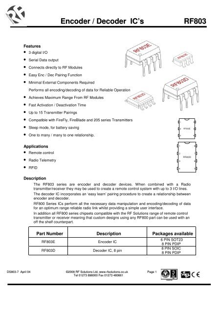
<strong>Encoder</strong> / <strong>Decoder</strong> IC’s<br />
<strong>RF803</strong><br />
Features<br />
• 3 digital I/O<br />
• Serial Data output<br />
• Connects directly to RF Modules<br />
• Easy Enc / Dec Pairing Function<br />
• Minimal External Components Required<br />
• Performs all encoding/decoding of data for Reliable Operation.<br />
• Achieves Maximum Range From RF Modules<br />
• Fast Activation / Deactivation Time<br />
• Up to 15 Transmitter Pairings<br />
• Compatible with FireFly, FireBlade and 205 series Transmitters<br />
• Sleep mode, for battery saving<br />
1 6<br />
2 <strong>RF803</strong>E 5<br />
• One to many / many to one relationship.<br />
3<br />
4<br />
Applications<br />
• Remote control<br />
• Radio Telemetry<br />
• RFID<br />
1 8<br />
2<br />
7<br />
<strong>RF803</strong>D<br />
3<br />
6<br />
4 5<br />
Description<br />
The <strong>RF803</strong> series are encoder and decoder devices. When combined with a Radio<br />
transmitter/receiver they may be used to create a remote control system with up to 3 I/O lines.<br />
The decoder IC incorporates an ‘easy learn’ pairing procedure to create a relationship between<br />
encoder and decoder.<br />
RF800 Series ICs perform all the necessary data manipulation and encoding/decoding of data<br />
for an optimum range reliable radio link whilst providing a simple user interface.<br />
In addition all RF800 series chipsets compatible with the RF Solutions range of remote control<br />
transmitter or receiver meaning that custom designs using any RF800 part can be used with an<br />
off the shelf counterpart.<br />
Part Number Description Packages available<br />
<strong>RF803</strong>E<br />
<strong>RF803</strong>D<br />
<strong>Encoder</strong> IC<br />
<strong>Decoder</strong> IC, 8 pin<br />
6 PIN SOT23<br />
8 PIN PDIP<br />
8 PIN SOIC<br />
8 PIN PDIP<br />
DS803-7 April 04 ©2008 RF Solutions Ltd, www.rfsolutions.co.uk Page 1<br />
Tel 01273 898000 Fax 01273 480661
<strong>Encoder</strong> / <strong>Decoder</strong> IC’s<br />
<strong>RF803</strong><br />
Transmitter <strong>Encoder</strong> <strong>RF803</strong>E<br />
Functional Description<br />
The <strong>RF803</strong>E is a simple device to use. As shown in the application circuit below, it requires only the<br />
addition of input switches and RF circuitry for use as the transmitter in the end application.<br />
Transmission is automatic without user intervention.<br />
On detecting a switch closure The <strong>RF803</strong>E will wake up transmit a secure data packet on the TX<br />
output.<br />
The <strong>RF803</strong>E uses a fully balanced Manchester encoded data protocol designed for optimum use of<br />
the radio transmission path.<br />
Each <strong>RF803</strong>E is programmed at the time of manufacture with a unique 16-bit serial number, which<br />
provides a secure way of addressing RF800 series devices. This provides up to 65,536 possible<br />
addresses.<br />
Compatibility with RF Solutions Receivers<br />
The <strong>RF803</strong> series are compatible with the FireFly/FireBlade series and 210-433/525/458 series of<br />
ready to operate receiver decoder units.<br />
This enables a designer to easily integrate a remote control function into an application using a<br />
ready made receiver<br />
DS803-7 April 04 ©2008 RF Solutions Ltd, www.rfsolutions.co.uk Page 2<br />
Tel 01273 898000 Fax 01273 480661
<strong>Encoder</strong> / <strong>Decoder</strong> IC’s<br />
<strong>RF803</strong><br />
Pin Descriptions <strong>RF803</strong>E<br />
See Page 8 for typical application circuit<br />
N/C<br />
1 8<br />
IP 3<br />
VCC<br />
TX<br />
2<br />
3<br />
<strong>RF803</strong>E<br />
PDIP<br />
DFN<br />
7<br />
6<br />
GND<br />
N/C<br />
IP 2<br />
4 5 IP1<br />
SOT23<br />
Pin<br />
Number<br />
Name<br />
Input /<br />
Output<br />
Description<br />
1 IP 1 IP Switch input 1 (active low)<br />
3 IP 2 IP Switch input 2 (active low)<br />
6 IP 3 IP Switch input 3 (active low)<br />
2 GND IP Supply GND<br />
4 TX OP Data output<br />
5 Vcc IP Supply Voltage<br />
PDIP<br />
Pin<br />
Input /<br />
Name<br />
Number<br />
Output<br />
Description<br />
1 - - Not Connected<br />
2 Vcc IP Supply Voltage<br />
3 TX OP Data output<br />
4 IP 2 IP Switch input 2 (active low)<br />
5 IP1 IP Switch Input 1 (active low)<br />
6 - - Not Connected<br />
7 GDN OP Ground Connection<br />
8 IP3 IP Switch Input 3 (active low)<br />
IP 1-3<br />
These are the switch inputs which when operated wake up the <strong>RF803</strong>E and cause transmission.<br />
They may be switched directly to Ground. Transmission occurs for the duration of the switch<br />
operation.<br />
Vcc<br />
The power supply needs to be a stable regulated voltage between 2.5 and 5.5V with
<strong>Encoder</strong> / <strong>Decoder</strong> IC’s<br />
<strong>RF803</strong><br />
Receiver <strong>Decoder</strong> <strong>RF803</strong>D<br />
Functional Description<br />
The <strong>RF803</strong>D is simple to use. As shown in the typical application circuits, in the stand alone<br />
operation the <strong>RF803</strong>D has the capability to learn up to 15 unique <strong>RF803</strong>E transmitters.<br />
Vcc<br />
STATUS LED<br />
LEARN<br />
SERIAL DATA<br />
MOM/LATCH<br />
RF806D<br />
O/P 1<br />
O/P 2<br />
O/P 3<br />
DATA IN<br />
GND<br />
The <strong>RF803</strong>D is connected directly to the data output of a radio receiver module and upon detection<br />
of a valid data packet it will decode the data stream. The <strong>RF803</strong>D will then assert its digital outputs<br />
which will match the state of the <strong>RF803</strong>E encoders’ learnt at the time of transmission.<br />
The digital outputs may be configured as latching or momentary action.<br />
Latch = the output will change state on each successive transmit of the encoder.<br />
Momentary = the output will only operate for as long as the <strong>RF803</strong>E encoder is transmitting.<br />
The <strong>RF803</strong>D requires only the addition of the following components<br />
1. A ‘Learn’ switch which is used in the process of learning a transmitter/encoder to the decoder<br />
and also to initiate erasure of encoder information.<br />
2. An LED which indicates the status of the learn process, the erase process and also data<br />
reception status.<br />
3. An Option link which configures the action of the digital outputs. This input may simply be tied<br />
to Vcc or GND.<br />
Compatibility with RF Solutions Transmitters:<br />
The <strong>RF803</strong> series are compatible with the FireFly/FireBlade series and 205 series of ready to<br />
operate transmitter encoders (when using FM)<br />
This enables a designer to integrate a remote control function into an application easily, by using a<br />
ready made transmitter.<br />
DS803-7 April 04 ©2008 RF Solutions Ltd, www.rfsolutions.co.uk Page 4<br />
Tel 01273 898000 Fax 01273 480661
<strong>Encoder</strong> / <strong>Decoder</strong> IC’s<br />
<strong>RF803</strong><br />
Pin Descriptions <strong>RF803</strong>D<br />
See Page 8 for application circuit example<br />
SOIC / PDIP<br />
Pin<br />
Number<br />
Name<br />
Input /<br />
Output<br />
7 OP1 Out Digital Output 1<br />
6 OP2 Out Digital Output 2<br />
5 OP3 Out Digital Output 3<br />
1 Vcc In Supply Voltage<br />
8 Vss In Supply GND<br />
Description<br />
2 SD/ML In/Out Serial Data Output / Momentary / Latching setting<br />
3 LRN In/Out Learn / Erase Function<br />
4 Rx In Rx Data input<br />
Vcc<br />
2.5-5.5V DC input. The power supply needs to be a stable regulated voltage with
<strong>Encoder</strong> / <strong>Decoder</strong> IC’s<br />
<strong>RF803</strong><br />
System and Functional operation<br />
Pairing a Transmitter to a Receiver<br />
Each transmitter has a unique identity. Each time a switch is pressed, the transmitter emits a highly<br />
secure RF signal. The Receiver can learn this signal and allocate to an output.<br />
Any transmitter switch may be paired to one or many of the receiver’s outputs, or a transmitter<br />
single switch may be paired to any number of receiver’s outputs to enable a powerful and flexible<br />
remote control system.<br />
The only limitation is that each receiver has a maximum capacity of 15 pairings, these can be from<br />
the same or any number of transmitters.<br />
Hint: the same transmitter may be taught to any number of receivers to create ‘master keys’.<br />
Learn Mode: Learn input activation is achieved by pulling this input to GND briefly<br />
To learn a new transmitter switch follow this procedure (as application circuit)<br />
Any <strong>Encoder</strong> input can be learnt to one or many of the receiver outputs.<br />
Each input must be learnt to each output individually by following this procedure:<br />
1. Select the receiver output to learn:<br />
a. Briefly operate the receiver Learn switch (SW1) once<br />
b. The Learn LED will flash once to indicate that output 1 is selected<br />
c. After the LED stops flashing, press the Learn switch again to select the next output<br />
channel<br />
d. Repeat step c until the required output is selected.<br />
2. Operate whichever input on the encoder you want to learn to the selected decoder output.<br />
3. The Learn LED will then illuminate, within 10secs, operate the same encoder input again.<br />
4. The Learn LED will then flash to indicate learning is complete.<br />
Erase Mode (As application circuit): is achieved by pulling this input to GND for >8 seconds. This<br />
causes the internal EEPROM to be erased of all pre-learnt <strong>RF803</strong>E encoders.<br />
During Erase the Learn LED will activate, it will extinguish when erase is complete.<br />
Mom / Latch<br />
This high impedance input is used to set the digital outputs to momentary or latched actions<br />
LKIN Status<br />
Open<br />
Closed<br />
Digital Outputs<br />
Function<br />
Latching<br />
Momentary<br />
Serial Data Output<br />
The <strong>RF803</strong>D has a serial data output. This outputs the serial number, button and battery status of<br />
the transmitter encoder (<strong>RF803</strong>E). This data may be fed directly to a microcontroller or RS232 type<br />
driver circuit which may then be fed directly to a PC serial port.<br />
Serial data is output initially and again every ½ second whilst data is being received from the<br />
<strong>RF803</strong>E transmitter. i.e. this output is valid regardless of whether the <strong>RF803</strong>E encoder has been<br />
learnt to the <strong>RF803</strong>D decoder or not. The serial data packet contains a learn bit to show if an<br />
encoder input is learnt.<br />
DS803-7 April 04 ©2008 RF Solutions Ltd, www.rfsolutions.co.uk Page 6<br />
Tel 01273 898000 Fax 01273 480661
<strong>Encoder</strong> / <strong>Decoder</strong> IC’s<br />
<strong>RF803</strong><br />
Serial Data Format<br />
Serial Data is sent every 1/2 second as a stream of 7 bytes at 9.6K baud. The serial data format is:<br />
8 data bits with 1 stop bit, no parity.<br />
Serial data is output form the <strong>Decoder</strong> chip whenever a valid data packet from an RF80n or other<br />
compatible RF Solutions transmitter is received regardless of learn<br />
N N X X STAT $0D $0A<br />
7 bytes of data transmitted<br />
LF Line feed (last character)<br />
CR Carriage return<br />
Battery Status / Learn Status<br />
<strong>Encoder</strong> Input information<br />
Output from Serial Data pin<br />
<strong>Encoder</strong> serial number<br />
<strong>Encoder</strong> Serial Number [NN]: made up of two 8-bit bytes where the most significant byte is<br />
transmitted first.<br />
This provides a total of 65,536 possible serial numbers.<br />
Example:<br />
12AB (hexadecimal) or 0001 0010 1010 1011 (binary)<br />
<strong>Encoder</strong> Input Information [XX]: made up of two 8-bit bytes.<br />
The high order byte is sent first representing inputs 16 down to 9 where the MSb is input 16 and the<br />
LSb is input 9.<br />
The low order byte is sent next representing inputs 8 down to 1 where the MSb is input 8 and the<br />
LSb is input 1.<br />
A bit at state 1 represents an encoder input as active.<br />
Using this method inputs can be multiplexed giving maximum versatility.<br />
Example:<br />
00000000 00001000 - Shows input 4 active.<br />
00000001 00000000 – Shows input 9 active<br />
10000001 00000001 – Shows inputs 16, 9 and 1 active<br />
Status [STAT]: The status byte is made up of an 8-bit byte as follows:<br />
BIT Description Details<br />
Bit-7 down to 2 Reserved For future usage<br />
Bit 1 Learn status 1 = encoder has been learnt<br />
Bit 0 Battery status 0 = encoder battery is OK<br />
1 = encoder battery is low<br />
Example:<br />
00000010 = encoder battery ok, encoder has been learnt<br />
00000001 = encoder battery low, encoder has not been learnt<br />
DS803-7 April 04 ©2008 RF Solutions Ltd, www.rfsolutions.co.uk Page 7<br />
Tel 01273 898000 Fax 01273 480661
<strong>Encoder</strong> / <strong>Decoder</strong> IC’s<br />
<strong>RF803</strong><br />
Carriage Return [CR] and Line feed [LF]<br />
To mark the end of the serial packet ascii characters for carriage return (hex 0D) are sent followed<br />
by LF (hex 0A).<br />
Custom Versions<br />
Custom versions of the <strong>RF803</strong>E / <strong>RF803</strong>D chipset are available to provide a bespoke remote<br />
chipset for OEM applications. Please contact our sales department for further information.<br />
*NOTE: Serial Data output is common across the entire RF80n range, therefore up to 16<br />
inputs states are sent. When using encoders with lower numbers of inputs the un-used bits<br />
are set to 0.<br />
DS803-7 April 04 ©2008 RF Solutions Ltd, www.rfsolutions.co.uk Page 8<br />
Tel 01273 898000 Fax 01273 480661
<strong>Encoder</strong> / <strong>Decoder</strong> IC’s<br />
<strong>RF803</strong><br />
Typical Applications:<br />
<strong>RF803</strong>D<br />
<strong>RF803</strong>E<br />
Vcc<br />
ANTENNA<br />
0.1uF,<br />
25V<br />
1 ENABLE<br />
ANT 6<br />
<strong>RF803</strong>E<br />
2 IN RTFQ1 GND 5<br />
` 3 GND Vcc 4<br />
0.1uF,<br />
25V<br />
1 N/C I/ P 3 8<br />
2 VCC<br />
3 TX<br />
GND 7<br />
N/C 6<br />
4 I/P 2 I/P 1 5<br />
GND<br />
GND<br />
NAND<br />
Gate<br />
I/P 2<br />
I/P 1<br />
I/P 3<br />
GND<br />
DS803-7 April 04 ©2008 RF Solutions Ltd, www.rfsolutions.co.uk Page 9<br />
Tel 01273 898000 Fax 01273 480661
<strong>Encoder</strong> / <strong>Decoder</strong> IC’s<br />
<strong>RF803</strong><br />
Technical Specifications:<br />
Absolute Maximum Ratings 803E and 803D<br />
Note: Stresses above those listed under “Absolute Maximum Ratings” may cause permanent damage to the device.<br />
Item Rating Units<br />
Supply voltage 2.0 – 5.5 V<br />
Max output current 80 mA<br />
Storage temperature -65 to +150 °C (Note)<br />
Lead soldering temp<br />
ESD rating<br />
°C (Note)<br />
Max O/P current sunk by any I/O pin 25 mA<br />
Max O/P current sourced by any I/O pin 25 mA<br />
<strong>RF803</strong>E<br />
Electrical Characteristics Min Typical Max Unit<br />
Operating current(average)<br />
Vdd = 5V<br />
603 645 689 µA<br />
Standby current .1 µA<br />
High level Input voltage 2.0 VDD V<br />
Low level input voltage VSS 0.8 V<br />
High level output voltage VDD - .7 V<br />
Low level output voltage 0.6 V<br />
Output Pin Current rating 25 mA<br />
LED sink current 75 mA<br />
<strong>RF803</strong>D<br />
Electrical Characteristics Min Typical Max Unit<br />
Operating current(average)<br />
Vdd = 2V<br />
1 mA<br />
Standby current - µA<br />
High level Input voltage 2.0 V<br />
Low level input voltage VSS 0.8 V<br />
High level output voltage VDD - .7 V<br />
Low level output voltage 0.6 V<br />
Output Pin Current rating 25 mA<br />
LED sink current 75 mA<br />
V<br />
DS803-7 April 04 ©2008 RF Solutions Ltd, www.rfsolutions.co.uk Page 10<br />
Tel 01273 898000 Fax 01273 480661
<strong>Encoder</strong> / <strong>Decoder</strong> IC’s<br />
<strong>RF803</strong><br />
Appendix – Package types<br />
6 PIN SOT-23 PACKAGE<br />
DS803-7 April 04 ©2008 RF Solutions Ltd, www.rfsolutions.co.uk Page 11<br />
Tel 01273 898000 Fax 01273 480661
<strong>Encoder</strong> / <strong>Decoder</strong> IC’s<br />
<strong>RF803</strong><br />
8 PIN SOIC PACKAGE<br />
DS803-7 April 04 ©2008 RF Solutions Ltd, www.rfsolutions.co.uk Page 12<br />
Tel 01273 898000 Fax 01273 480661
<strong>Encoder</strong> / <strong>Decoder</strong> IC’s<br />
<strong>RF803</strong><br />
8 PIN PDIP PACKAGE<br />
DS803-7 April 04 ©2008 RF Solutions Ltd, www.rfsolutions.co.uk Page 13<br />
Tel 01273 898000 Fax 01273 480661