DS-C-DO8RH/S, DS-C-DO8RH DS-C-DO8R Datenblatt ... - DEOS AG
DS-C-DO8RH/S, DS-C-DO8RH DS-C-DO8R Datenblatt ... - DEOS AG
DS-C-DO8RH/S, DS-C-DO8RH DS-C-DO8R Datenblatt ... - DEOS AG

Create successful ePaper yourself
Turn your PDF publications into a flip-book with our unique Google optimized e-Paper software.
<strong>Datenblatt</strong> / Data sheet <strong>DS</strong>-C-<strong><strong>DO8R</strong>H</strong>/S, <strong>DS</strong>-C-<strong><strong>DO8R</strong>H</strong><br />
OPEN IO Modul - CAN-Bus<br />
Technische Änderungen und Irrtümer vorbehalten. Stand: 30.10.2013<br />
<strong>DS</strong>-C-<strong>DO8R</strong><br />
OPEN IO Module - CAN-bus<br />
Errors and changes excepted. Issue date: 30.10.2013<br />
Seite 1<br />
page 1<br />
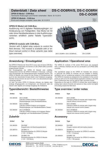
OPEN IO Modul mit CAN-Bus.<br />
Ausführung mit 8 digitalen Relaisausgängen zur<br />
Ansteuerung von Feldgeräten. Das Modul ist mit<br />
oder ohne Handbedienebene in drei Ausführungsvarianten<br />
erhältlich (siehe Tabelle Typenübersicht).<br />
OPEN IO module with CAN-Bus.<br />
Version with 8 digital relay outputs to control the<br />
fi eld devices. The module is available with or without<br />
manual control in three variants (see table<br />
type overview).<br />
<strong>DS</strong>-C-<strong><strong>DO8R</strong>H</strong> / <strong>DS</strong>-C-<strong><strong>DO8R</strong>H</strong>/S<br />
<strong>DS</strong>-C-<strong>DO8R</strong><br />
Anwendung / Einsatzgebiet<br />
Application / Operational area<br />
© <strong>DEOS</strong> control systems GmbH 2013. Technische Änderungen und Irrtümer vorbehalten / Errors and changes excepted.<br />
Die OPEN IO Module der Serie <strong>DS</strong>-C-xxxxx sind mit einer CAN-Bus<br />
Schnittstelle ausgerüstet und können an alle OPEN EMS Controller<br />
angeschlossen werden.<br />
Die Einsatzgebiete der OPEN IO Module sind vielfältig.<br />
Insbesondere können die OPEN IO Module in Heizungs-, Lüftungsoder<br />
Klimaanlagen der Gebäudeautomation eingesetzt werden. Die<br />
OPEN IO Module sind sowohl für den Einbau im Schaltschrank als<br />
auch für den dezentralen Einsatz direkt in der Feldebene ausgelegt.<br />
Darüber hinaus können sie auch für Licht- und Jalousiesteuerungen<br />
verwendet werden.<br />
Je nach Typ eines OPEN IO Modules erfassen sie digitale oder<br />
analoge Eingangswerte von Ereignissen und Sensoren oder sie<br />
steuern über digitale und analoge Ausgänge die Feldebene.<br />
Typenübersicht / Bestellhinweise<br />
Artikel<br />
<strong>DS</strong>-390038<br />
<strong>DS</strong>-390039<br />
<strong>DS</strong>-390040<br />
Zubehör<br />
Artikel<br />
Typ<br />
<strong>DS</strong>-C-<strong>DO8R</strong><br />
CAN-Bus OPEN IO Modul mit 8 digitalen<br />
Relaisausgängen ohne Handbedienebene.<br />
<strong>DS</strong>-C-<strong><strong>DO8R</strong>H</strong><br />
CAN-Bus OPEN IO Modul mit 8 digitalen<br />
Relaisausgängen und Handbedienebene (Taster).<br />
<strong>DS</strong>-C-<strong><strong>DO8R</strong>H</strong>/S<br />
CAN-Bus OPEN IO Modul mit 8 digitalen Relaisausgängen<br />
und Handbedienebene (Schalter).<br />
Typ<br />
<strong>DS</strong>-390024 <strong>DS</strong>-PKM<br />
Koppelmodul mit Abschlusswiderstand<br />
<strong>DS</strong>-390019 <strong>DS</strong>-BBS 10<br />
Brückenbusstecker für OPEN IO Module<br />
(1 VE = 10 Stück)<br />
<strong>DS</strong>-390020 <strong>DS</strong>-BBS 100<br />
Brückenbusstecker für OPEN IO Module<br />
(1 VE = 100 Stück)<br />
The OPEN IO modules of the series <strong>DS</strong>-C-xxxxx are equipped<br />
with a CAN-Bus interface and can be connected to all OPEN EMS<br />
controller.<br />
The operational areas of the OPEN IO modules are various.<br />
In particular the OPEN IO modules can be installed in heating,<br />
ventilation and air conditioning systems in the building automation.<br />
The OPEN IO modules are designed for the installation in the control<br />
panel as well as for the decentralized application directly in the fi eld<br />
level. Furthermore they can be used for light- and blind control.<br />
Depending on the type of a OPEN IO module they record digital or<br />
analog input values of events and sensors or they control via digital<br />
and analog outputs the fi eld level.<br />
Type overview / order notes<br />
Article<br />
<strong>DS</strong>-390038<br />
<strong>DS</strong>-390039<br />
<strong>DS</strong>-390040<br />
Accessory<br />
Article<br />
Type<br />
<strong>DS</strong>-C-<strong>DO8R</strong><br />
CAN-Bus OPEN IO module with 8 digital relay<br />
outputs without manual control.<br />
<strong>DS</strong>-C-<strong><strong>DO8R</strong>H</strong><br />
CAN-Bus OPEN IO module with 8 digital relay<br />
outputs and manual control (taster).<br />
<strong>DS</strong>-C-<strong><strong>DO8R</strong>H</strong>/S<br />
CAN-Bus OPEN IO module with 8 digital relay<br />
outputs and manual control (switch).<br />
Type<br />
<strong>DS</strong>-390024 <strong>DS</strong>-PKM<br />
Coupler module with terminating resistor<br />
<strong>DS</strong>-390019 <strong>DS</strong>-BBS 10<br />
Bridge bus connector for OPEN IO modules<br />
(1 PU = 10 pieces)<br />
<strong>DS</strong>-390020 <strong>DS</strong>-BBS 100<br />
Bridge bus connector for OPEN IO modules<br />
(1 PU = 100 pieces)<br />
<strong>DEOS</strong> control systems GmbH<br />
48432 Rheine Tel.: +49 5971 911332-0 E-Mail: info@deos-ag.com<br />
Birkenallee 113 Fax: +49 5971 911332-995 www.deos-ag.com<br />
Ein Unternehmen der
<strong>Datenblatt</strong> / Data sheet <strong>DS</strong>-C-<strong><strong>DO8R</strong>H</strong>/S, <strong>DS</strong>-C-<strong><strong>DO8R</strong>H</strong><br />
OPEN IO Modul - CAN-Bus<br />
Technische Änderungen und Irrtümer vorbehalten. Stand: 30.10.2013<br />
<strong>DS</strong>-C-<strong>DO8R</strong><br />
OPEN IO Module - CAN-bus<br />
Errors and changes excepted. Issue date: 30.10.2013<br />
Seite 2<br />
page 2<br />
© <strong>DEOS</strong> control systems GmbH 2013. Technische Änderungen und Irrtümer vorbehalten / Errors and changes excepted.<br />
Sicherheitshinweis<br />
Der Umgang mit diesem Gerät darf nur durch entsprechend<br />
geschultes Personal erfolgen, das berechtigt ist, Arbeiten an<br />
elektrischen Anlagen auszuführen.<br />
Die Geräte dürfen nicht in Verbindung mit Geräten benutzt<br />
werden, die direkt oder indirekt menschlichen, gesundheits- oder<br />
lebenssichernden Zwecken dienen oder durch deren Betrieb<br />
Gefahren für Menschen, Tiere oder Sachwerte entstehen können.<br />
Das Gerät muss außer Betrieb gesetzt werden, wenn ein gefahrloser<br />
Betrieb (z.B. sichtbare Beschädigungen) nicht mehr gewährleistet<br />
ist. Der Garantieanspruch erlischt beim Öffnen des Gerätes.<br />
Elektrischer Anschluss<br />
Die Geräte sind für den Betrieb an Kleinspannung ausgelegt.<br />
Beim elektrischen Anschluss der Geräte sind die techn. Daten zu<br />
berücksichtigen.<br />
Die Geräte müssen bei einer konstanten Betriebsspannung<br />
betrieben werden. Strom-/Spannungsspitzen beim Ein-/Ausschalten<br />
der Versorgungsspannung müssen bauseits vermieden werden.<br />
Die Versorgungs- und Signalleitungen müssen nach dem<br />
aktuellen Stand der Technik angeschlossen und verlegt werden.<br />
Insbesondere sind bei der Verlegung von Sensorleitungen mögliche<br />
Störeinkopplungen durch parallel verlaufende Fremdleitungen zu<br />
vermeiden.<br />
Für die Verlegung der CAN-Bus Leitungen ist auf die Einhaltung der<br />
Spezifikationen für den Aufbau eines CAN-Bus-Systems zu achten.<br />
Montagehinweise<br />
Die Montage ist nach gültigen Installationsstandards durch<br />
geschultes Personal auszuführen.<br />
Die Montage der Geräte erfolgt auf Standard-(Norm) Hutschiene 35<br />
mm in Schaltschränken.<br />
Bei der Festlegung des Montageortes ist zu beachten, dass die<br />
Grenzen der Betriebstemperatur nicht überschritten werden.<br />
Für die Montage in Zwischendecken sind geeignete Gehäuse<br />
vorzusehen. Nötigenfalls sind Revisionsöffnungen einzuplanen.<br />
Bei der Montage ist darauf zu achten, dass die offenen Teile des<br />
Gerätes frei von Verschmutzungen sind - insbesondere kann das<br />
Gerät durch Eindringen von Metallspänen zerstört werden.<br />
Hinweis:<br />
Bei Verwendung von Schraubklemmen, darf das maximale<br />
Anzugsmoment der Schraubklemmen 0,4 Nm nicht übersteigen.<br />
Das Überschreiten des max. Anzugsmomentes kann zur Zerstörung<br />
der Klemme führen. Dadurch kann der elektrische Kontakt an der<br />
Klemme nicht mehr gewährleistet werden.<br />
!<br />
Safety guidelines<br />
Handling with this equipment may take place only through trained<br />
personnel, who is entitled to implement work on electrical system.<br />
The devices may not be used in connection with devices which<br />
serve directly or indirectly human health or life-securing purposes or<br />
which can arise danger for humans, animals or material assets.<br />
The device must be set out of service, if a safe operation (e.g.<br />
visible damages) is no longer possible. With an interference into the<br />
equipment the warranty claim expires!<br />
Electric connection<br />
The devices are appropriate for the operation at low voltage.<br />
During the electrical connection of the devices, the technical data of<br />
the devices are valid.<br />
The devices must be operated during a constant operating voltage.<br />
Current/voltage peaks when switching on/off of the supply voltage<br />
must be avoided on site.<br />
The supply- and signal lines must be connected and laid according<br />
the current state of the art. In particular possible interference<br />
couplings have to be avoided by parallel running foreign lines with<br />
the transfer of sensor lines.<br />
For the transfer of the CAN-Bus lines it is important to pay attention<br />
to the adherence of the specifications for the structure of a CAN-Bus<br />
system.<br />
Mounting advices<br />
The assembly is to be implemented after installation standards<br />
by trained personnel. The assembly of the devices takes place on<br />
standard (norm) DIN rail 35 mm in cabinets.<br />
When defining the assembly place it should be noted that the limits<br />
of the operating temperatures are not exceeded.<br />
For the assembly in intermediate ceilings suitable housings have to<br />
be planned. If necessary, inspection openings have to be planned.<br />
When assembling it is important to be certain, that the open parts<br />
of the device are free from pollution - in particular the device can be<br />
destroyed by penetratoin of metal chips.<br />
Note:<br />
By using screw terminals the maximum torque of the screw<br />
terminals may not exceed 0.4 Nm. The exceeding of the max.<br />
torque can lead to the destruction of the terminal. Thus the electrical<br />
contact at the terminal cannot be ensured no more.<br />
!<br />
<strong>DEOS</strong> control systems GmbH<br />
48432 Rheine Tel.: +49 5971 911332-0 E-Mail: info@deos-ag.com<br />
Birkenallee 113 Fax: +49 5971 911332-995 www.deos-ag.com<br />
Ein Unternehmen der
<strong>Datenblatt</strong> / Data sheet <strong>DS</strong>-C-<strong><strong>DO8R</strong>H</strong>/S, <strong>DS</strong>-C-<strong><strong>DO8R</strong>H</strong><br />
OPEN IO Modul - CAN-Bus<br />
Technische Änderungen und Irrtümer vorbehalten. Stand: 30.10.2013<br />
<strong>DS</strong>-C-<strong>DO8R</strong><br />
OPEN IO Module - CAN-bus<br />
Errors and changes excepted. Issue date: 30.10.2013<br />
Seite 3<br />
page 3<br />
Inbetriebnahme<br />
Voraussetzung für die Inbetriebnahme ist die ordnungsgemäße<br />
Installation aller elektrischen Versorgungs-, Schalt- und<br />
Messleitungen. Vor dem Einschalten der Betriebsspannung ist diese<br />
auf richtigen Anschluss zu prüfen.<br />
Anschlussmöglichkeiten<br />
Die OPEN IO Module sind für den Einsatz im gebäudetechnischen<br />
Umfeld ausgelegt. Die digitalen und analogen Eingänge der OPEN<br />
IO Module können mit branchenüblichen Sensoren beschaltet<br />
werden. Die Spezifikationen der Sensoren können den jeweiligen<br />
Datenblättern entnommen werden.<br />
Commissioning<br />
A condition for commissioning is the normal installation of all<br />
electrical supply- , switch and measuring lines.<br />
Before switching on the operating voltage the correct connection<br />
has to be assured.<br />
Connection possibilities<br />
The OPEN IO modules are appropriate for the application in the<br />
building technology environment. The digital and analog inputs of<br />
the OPEN IO modules can be wired with customary sensors. The<br />
specifications of the sensors can be extracted from the respective<br />
data sheets.<br />
© <strong>DEOS</strong> control systems GmbH 2013. Technische Änderungen und Irrtümer vorbehalten / Errors and changes excepted.<br />
<strong>DEOS</strong> control systems GmbH<br />
48432 Rheine Tel.: +49 5971 911332-0 E-Mail: info@deos-ag.com<br />
Birkenallee 113 Fax: +49 5971 911332-995 www.deos-ag.com<br />
Ein Unternehmen der
<strong>Datenblatt</strong> / Data sheet <strong>DS</strong>-C-<strong><strong>DO8R</strong>H</strong>/S, <strong>DS</strong>-C-<strong><strong>DO8R</strong>H</strong><br />
OPEN IO Modul - CAN-Bus<br />
Technische Änderungen und Irrtümer vorbehalten. Stand: 30.10.2013<br />
<strong>DS</strong>-C-<strong>DO8R</strong><br />
OPEN IO Module - CAN-bus<br />
Errors and changes excepted. Issue date: 30.10.2013<br />
Seite 4<br />
page 4<br />
Technische Daten<br />
Gehäuse:<br />
• Abmessungen (BxTxH): 54 mm x 60 mm x 90 (98) mm<br />
• Material:<br />
Kunststoff<br />
• Montage:<br />
auf Standard-Hutschiene 35 mm<br />
• Schutzart: IP 20<br />
• Kühlung:<br />
lüfterlos durch Konvektion<br />
• Temperaturbereich: 0..50 °C<br />
• Anschluss:<br />
abziehbare Federzugklemmen<br />
Nennquerschnitt 1,5 mm²<br />
• Adress-Schalter zur Einstellung der Bus-Adresse<br />
• LED zur Betriebsanzeige<br />
• LED zur Anzeige des Bus-Zustands<br />
• Einbaulage:<br />
beliebig<br />
Technical data<br />
Housing:<br />
• Dimensions (WxDxH): 54 mm x 60 mm x 90 (98) mm<br />
• Material:<br />
Plastic<br />
• Mounting:<br />
on Standard mounting rail 35 mm<br />
• Protection class: IP 20<br />
• Cooling:<br />
no fan ; by convection<br />
• Temperature range: 0..50 °C<br />
• Connection:<br />
removable spring terminals<br />
Nominal wire 1,5 mm²<br />
• Address-switch for setting the Bus-address<br />
• LED for operating display<br />
• LED for signalling of the bus status<br />
• Mounting position: optional<br />
Spannungsversorgung:<br />
• Eingangsspannung:<br />
• Eingangsstrom:<br />
• Leistungsaufnahme:<br />
• max. Vorsicherung:<br />
• Schutzbeschaltung:<br />
U(nenn) = 24 V DC (19 .. 30 V DC)<br />
I(nenn) = ca. 100 mA<br />
ca. 2,5 W<br />
2 A<br />
Verpolungsschutz der<br />
Eingangsspannung<br />
Power supply:<br />
• Input voltage:<br />
• Input current:<br />
• Power consumption:<br />
• max. back-up fuse:<br />
• Protective circuit:<br />
U(nom) = 24 V DC (19 .. 30 V DC)<br />
I(nom) = approx. 100 mA<br />
approx. 2,5 W<br />
2 A<br />
reverse pole protection of the input<br />
voltage<br />
Mikroprozessor und Speicher:<br />
• CPU:<br />
ARM7 Architektur<br />
• Schnittstellen:<br />
1x CAN-Bus<br />
Micro processor and memory:<br />
• CPU:<br />
ARM7 Architecture<br />
• Interfaces:<br />
1x CAN-Bus<br />
© <strong>DEOS</strong> control systems GmbH 2013. Technische Änderungen und Irrtümer vorbehalten / Errors and changes excepted.<br />
Kommunikation:<br />
• CAN-Bus:<br />
• Übertragungsrate:<br />
• Busleitung:<br />
• Busabschlusswiderstand:<br />
Relaisausgänge:<br />
• Ausgangskontakte:<br />
CAN 2.0B,<br />
galvanisch getrennt ISO 11898<br />
10 kbit/s...250 kbit/s,<br />
voreingestellt 50 kbit/s<br />
CAN-Bus Leitung,<br />
Wellenwiderstand R W<br />
= 120 Ohm<br />
R W<br />
am Anfang und am Ende<br />
des Busses<br />
8 Relaisausgänge<br />
mit Anzeige LEDs (gelb)<br />
davon<br />
4 Wechsler, 4 Schließer<br />
max. 6 A pro Relaiskontakt<br />
max. 10 A pro Modul<br />
500 mW pro Relaiskontakt<br />
• Vorsicherung:<br />
• Schaltlast:<br />
• Minimale Schaltleistung:<br />
• Kontaktbelastbarkeit: 230 V AC; 3,0 A / AC1 1<br />
230 V AC; 0,8 A / AC15 2<br />
30 V DC; 3 A / DC1 3<br />
230 V DC; 0,1 A / DC1<br />
1 AC1 = Ohmsche Last<br />
2 AC15 =Steuern elektromagnetischer Last, Hilfsstromschalter, Leitungsschütze, Magnetventile<br />
und Elektromagnete<br />
3 DC1 = Ohmsche Last. Nichtinduktive oder nur schwach induktive Last.<br />
Communication:<br />
• CAN-Bus:<br />
• Transmission rate:<br />
• Bus line:<br />
• Terminating resistor:<br />
• of the bus<br />
Relay outputs:<br />
• Output contacts:<br />
CAN 2.0B,<br />
galvanically isolated ISO 11898<br />
10 kbit/s...250 kbit/s,<br />
default 50 kbit/s<br />
CAN-Bus line<br />
wave impedance R W<br />
= 120 Ohm<br />
R W<br />
at the beginning and at the end<br />
of the bus<br />
8 relay outputs<br />
with LED displays (yellow)<br />
4 changeover contacts,<br />
4 normally open contacts<br />
max. 6 A per relay contact<br />
• Back-up fuse:<br />
• Switching load:<br />
max. 10 A per module<br />
• Minimum switching capacity: 500 mW per relay contact<br />
• Contact load : 230 V AC; 3,0 A / AC1 1<br />
230 V AC; 0,8 A / AC15 2<br />
30 V DC; 3 A / DC1 3<br />
230 V DC; 0,1 A / DC1<br />
1 AC1 = Ohmic load<br />
2 AC15 = control of electromagnetic load, control switch,<br />
contactors, solenoid valves and electromagnets<br />
3 DC1 = Ohmic load. Non-inductive or only low inductive load.<br />
<strong>DEOS</strong> control systems GmbH<br />
48432 Rheine Tel.: +49 5971 911332-0 E-Mail: info@deos-ag.com<br />
Birkenallee 113 Fax: +49 5971 911332-995 www.deos-ag.com<br />
Ein Unternehmen der
<strong>Datenblatt</strong> / Data sheet <strong>DS</strong>-C-<strong><strong>DO8R</strong>H</strong>/S, <strong>DS</strong>-C-<strong><strong>DO8R</strong>H</strong><br />
OPEN IO Modul - CAN-Bus<br />
Technische Änderungen und Irrtümer vorbehalten. Stand: 30.10.2013<br />
<strong>DS</strong>-C-<strong>DO8R</strong><br />
OPEN IO Module - CAN-bus<br />
Errors and changes excepted. Issue date: 30.10.2013<br />
Seite 5<br />
page 5<br />
Anzeige- und Bedienelemente<br />
Display and control elements<br />
1 Status LED S1 / Status LED S1<br />
2 Anzeige und Bedienelemente / Display and control elements<br />
3 Anschlusskontakte für Brückenbusstecker<br />
(CAN-Bus und Spannungsversorgung)<br />
contacts for bridge bus connectors<br />
(CAN-Bus and Power supply)<br />
4 Adressschalter Low / Address switch Low<br />
5 Adressschalter High / Address switch High<br />
6 Status LED S2 / Status LED S2<br />
Spannungsversorgung / Busanschluss<br />
Power supply / Bus connection<br />
Die Einspeisung der Versorgungsspannung und des CAN-<br />
Busses für die OPEN IO Module erfolgt in Verbindung mit dem<br />
Koppelmodul <strong>DS</strong>-PKM über einen Brückenbusstecker.<br />
The input of the supply voltage and the CAN bus for the OPEN IO<br />
modules take place in connection with the coupling module <strong>DS</strong>-<br />
PKM via the bridge bus connector.<br />
© <strong>DEOS</strong> control systems GmbH 2013. Technische Änderungen und Irrtümer vorbehalten / Errors and changes excepted.<br />
Klemmenbelegung Spannungsversorgung und CAN-Bus<br />
Terminal configuration Power supply and CAN-Bus<br />
CG<br />
H<br />
L<br />
0V<br />
+ 24V<br />
3<br />
Hinweis:<br />
Bis zu 15 aufeinanderfolgende Module dürfen über den Busstecker<br />
miteinander verbunden werden. Darüber hinaus muss eine weitere<br />
externe Einspeisung der Spannungsversorgung erfolgen.<br />
Note:<br />
Up to 15 successive modules can be connected together via a bus<br />
connector. In addition, another external supply voltage input have to<br />
take place.<br />
* Nicht belegte Klemmen dürfen nicht als Klemmstützpunkt belegt werden.<br />
* Unused terminals must not be used as connecting terminals.<br />
CAN-Bus für OPEN IO Module<br />
CAN-bus for OPEN IO modules<br />
Anschlusskontakte für Brückenbusstecker<br />
contacts for bridge bus connectors<br />
PIN / Pin<br />
CG<br />
H<br />
L<br />
Signal / signal<br />
CAN-Ground<br />
CAN-High<br />
CAN-Low<br />
Spannungsversorgung für OPEN IO Module<br />
Power supply for OPEN IO modules<br />
Anschlusskontakte für Brückenbusstecker<br />
contacts for bridge bus connectors<br />
PIN / Pin Signal / signal<br />
0 V Masse / GND<br />
+24 V +24 V DC<br />
<strong>DEOS</strong> control systems GmbH<br />
48432 Rheine Tel.: +49 5971 911332-0 E-Mail: info@deos-ag.com<br />
Birkenallee 113 Fax: +49 5971 911332-995 www.deos-ag.com<br />
Ein Unternehmen der
<strong>Datenblatt</strong> / Data sheet <strong>DS</strong>-C-<strong><strong>DO8R</strong>H</strong>/S, <strong>DS</strong>-C-<strong><strong>DO8R</strong>H</strong><br />
OPEN IO Modul - CAN-Bus<br />
Technische Änderungen und Irrtümer vorbehalten. Stand: 30.10.2013<br />
<strong>DS</strong>-C-<strong>DO8R</strong><br />
OPEN IO Module - CAN-bus<br />
Errors and changes excepted. Issue date: 30.10.2013<br />
Klemmenbelegung / Terminal configuration<br />
Seite 6<br />
page 6<br />
C-<strong><strong>DO8R</strong>H</strong><br />
C-<strong><strong>DO8R</strong>H</strong>/S<br />
C-<strong>DO8R</strong><br />
© <strong>DEOS</strong> control systems GmbH 2013. Technische Änderungen und Irrtümer vorbehalten / Errors and changes excepted.<br />
2a<br />
2b<br />
Anzeige LEDs und Bedienelemente<br />
Digital-Ausgänge DO0 ... DO3<br />
LED display and control elements<br />
digital outputs DO0 ... DO3<br />
Anzeige LEDs und Bedienelemente<br />
Digital-Ausgänge DO4 ... DO7<br />
LED display and control elements<br />
digital outputs DO4 ... DO7<br />
Hinweise:<br />
Nicht belegte Klemmen dürfen nicht als<br />
Klemmstützpunkt belegt werden.<br />
Anzugsmoment bei Verwendung von<br />
Schraubklemmen - max. 0,4 Nm<br />
2a<br />
2b<br />
Anzeige LEDs Digital-Ausgänge DO0 ... DO3<br />
LED display digital outputs DO0 ... DO3<br />
Anzeige LEDs Digital-Ausgänge DO4 ... DO7<br />
LED display digital outputs DO4 ... DO7<br />
Note:<br />
Unused terminals may not be used as connecting<br />
terminal.<br />
Tightening torque by using<br />
the screw terminals - max. 0,4 Nm<br />
<strong>DEOS</strong> control systems GmbH<br />
48432 Rheine Tel.: +49 5971 911332-0 E-Mail: info@deos-ag.com<br />
Birkenallee 113 Fax: +49 5971 911332-995 www.deos-ag.com<br />
Ein Unternehmen der
<strong>Datenblatt</strong> / Data sheet <strong>DS</strong>-C-<strong><strong>DO8R</strong>H</strong>/S, <strong>DS</strong>-C-<strong><strong>DO8R</strong>H</strong><br />
OPEN IO Modul - CAN-Bus<br />
Technische Änderungen und Irrtümer vorbehalten. Stand: 30.10.2013<br />
<strong>DS</strong>-C-<strong>DO8R</strong><br />
OPEN IO Module - CAN-bus<br />
Errors and changes excepted. Issue date: 30.10.2013<br />
Seite 7<br />
page 7<br />
Bedien-Funktionselemente<br />
CAN-Bus Adresse einstellen (High / Low)<br />
Über diese Adress-Schalter wird die Adresse des OPEN IO<br />
Moduls eingestellt. Über die Adresse wird ein OPEN IO Modul am<br />
CAN-Bus eindeutig identifiziert. Für die Adresssierung werden die<br />
Schalterstellungen jeweils „0“ bis „9“ verwendet. Dadurch sind Bus<br />
Adressen von „01“ bis „99“ einstellbar. Die Adresse „00“ und die<br />
jeweiligen Schalterstellungen „A“ bis „F“ werden nicht verwendet.<br />
Status LED S1 und S2<br />
Über die Status LEDs S1 und S2 wird der aktuelle Betriebszustand<br />
des OPEN IO Moduls angezeigt:<br />
Control- Functional elements<br />
Configure the CAN-Bus address (High / Low)<br />
The address of the OPEN IO modules will be adjusted via this address<br />
switch. By this address a OPEN IO module will be clearly identified<br />
at a CAN-Bus. For the addressing the switching positions are used<br />
in each case „0“ to „9“.Therefore Bus addresses are adjustable from<br />
„01“ to „99“. The address „00“ and the respective switching positions<br />
„A“ to „F“ are unused.<br />
Status LED S1 and S2<br />
The current operating state of the OPEN IO module is displayed via<br />
the status LEDs S1 and S2:<br />
© <strong>DEOS</strong> control systems GmbH 2013. Technische Änderungen und Irrtümer vorbehalten / Errors and changes excepted.<br />
S1 S2 Bedeutung<br />
grün<br />
blinkend<br />
gelb<br />
blinkend<br />
grün/<br />
gelb<br />
blinkend<br />
aus<br />
rot<br />
blinkend<br />
rot<br />
gelb<br />
Normaler Betriebszustand: Die<br />
Bus-Adresse ist auf einen gültigen<br />
Bereich eingestellt (01..99). In diesem<br />
Betriebszustand wird über die Status LED<br />
S2 der Bus-Zustand angezeigt.<br />
Das OPEN IO Modul wird von einer<br />
OPEN EMS angesprochen.<br />
Das Modul erkennt gültige CAN-<br />
Telegramme am Bus. Es wird aber<br />
nicht direkt von einer OPEN EMS<br />
angesprochen. Die eingestellten Adressen<br />
sollten überprüft werden.<br />
Es werden keine gültigen CAN-<br />
Telegramme am Bus erkannt.<br />
Beim Versenden eines CAN-Telegramms<br />
ist ein Fehler aufgetreten. Es wurden keine<br />
weiteren CAN-Teilnehmer am Bus erkannt.<br />
Eine ungültige Adresse ist eingestellt.<br />
Das OPEN IO Modul befindet sich im<br />
Service-Betrieb.<br />
gelb gelb Wenn beide LEDs gelb leuchten, wurde<br />
direkt zuvor ein Adressschalter verdreht.<br />
Nach einigen Sekunden übernimmt das<br />
Modul die neue Bus-Adresse.<br />
grün<br />
Interner Hardware Konfigurationsfehler.<br />
schnell<br />
blinkend<br />
rot<br />
schnell<br />
blinkend<br />
Interner Hardware Konfigurationsfehler.<br />
S1 S2 Description<br />
green<br />
flashing<br />
yellow<br />
flashing<br />
green/<br />
yellow<br />
flashing<br />
off<br />
red<br />
flashing<br />
red<br />
yellow<br />
Normal operating state: The Bus-address<br />
is set on a valid range (01..99). . In this<br />
operating state the Bus status is displayed<br />
via the status LED S2.<br />
The OPEN IO module is connected to the<br />
OPEN EMS.<br />
The module recognizes valid CANtelegrams<br />
at the Bus. But the module is not<br />
directly addressed by a OPEN EMS. The<br />
set addresses should be checked.<br />
No valid CAN-telegram is recognized on<br />
the Bus.<br />
By sending a CAN-telegram an error<br />
occured. No further CAN-devices were<br />
recognized at the Bus.<br />
An invalid address is set.<br />
The OPEN IO module is in the<br />
service-mode.<br />
yellow yellow If both LEDs shine yellow, an address<br />
switch was twisted directly before. After<br />
some seconds the module accepts the<br />
new Bus-address.<br />
green<br />
Internal hardware configuration fault.<br />
fast<br />
flashing<br />
red fast<br />
flashing<br />
Internal hardware configuration fault.<br />
<strong>DEOS</strong> control systems GmbH<br />
48432 Rheine Tel.: +49 5971 911332-0 E-Mail: info@deos-ag.com<br />
Birkenallee 113 Fax: +49 5971 911332-995 www.deos-ag.com<br />
Ein Unternehmen der
<strong>Datenblatt</strong> / Data sheet <strong>DS</strong>-C-<strong><strong>DO8R</strong>H</strong>/S, <strong>DS</strong>-C-<strong><strong>DO8R</strong>H</strong><br />
OPEN IO Modul - CAN-Bus<br />
Technische Änderungen und Irrtümer vorbehalten. Stand: 30.10.2013<br />
<strong>DS</strong>-C-<strong>DO8R</strong><br />
OPEN IO Module - CAN-bus<br />
Errors and changes excepted. Issue date: 30.10.2013<br />
Seite 8<br />
page 8<br />
Bedeutung der LED Anzeigen<br />
Digital-Ausgänge OPEN IO Module<br />
DO8T / DO8TH / <strong>DO8R</strong> / <strong><strong>DO8R</strong>H</strong><br />
LED<br />
gelb leuchtend<br />
Aus<br />
Bedeutung<br />
Der Ausgang ist geschaltet.<br />
Bei DO8T / DO8TH liegt 24 V DC am<br />
Ausgang an, bei <strong>DO8R</strong> / <strong><strong>DO8R</strong>H</strong> ist das<br />
Relais angezogen.<br />
Am Ausgang liegt 0 V an.<br />
Bei DO8T / DO8TH liegt 0V DC am<br />
Ausgang an, bei <strong>DO8R</strong> / <strong><strong>DO8R</strong>H</strong> ist das<br />
Relais nicht angezogen.<br />
Hinweis:<br />
Befindet sich ein Ausgang im Hand-Betrieb, so wird der aktuelle<br />
Betriebszustand angezeigt.<br />
Diese Anzeige wird durch Blinken einer Folge sehr kurzer Blink-<br />
Impulse unterbrochen, um den Handbetrieb zu signalisieren.<br />
Function of the LED indicators<br />
Digital-Outputs OPEN IO modules<br />
DO8T / DO8TH / <strong>DO8R</strong> / <strong><strong>DO8R</strong>H</strong><br />
LED<br />
bright yellow<br />
off<br />
Function<br />
The output is switched.<br />
At DO8T / DO8TH is 24 V DC on the<br />
output, at <strong>DO8R</strong> / <strong><strong>DO8R</strong>H</strong> the relay is<br />
energized.<br />
At the output is at 0 volts.<br />
At DO8T / DO8TH is 0V DC at the<br />
output, at <strong>DO8R</strong> / <strong><strong>DO8R</strong>H</strong> the relay is not<br />
energized.<br />
Note:<br />
If an output is in manual mode, the current operating state is<br />
displayed.<br />
This display is interrupted by flashing a series of very short flash<br />
pulses to signal the manual mode.<br />
© <strong>DEOS</strong> control systems GmbH 2013. Technische Änderungen und Irrtümer vorbehalten / Errors and changes excepted.<br />
Funktionsweise der Handbedienung bei<br />
OPEN IO Modulen mit Handbedienebene<br />
Bedienung der Hand-Ebene (Taster)<br />
IO Module<br />
DO8TH / <strong><strong>DO8R</strong>H</strong><br />
Hand EIN<br />
á (3 Sek.)<br />
Hand AUS<br />
â (3 Sek.)<br />
AUTO<br />
á oder â kurz<br />
tasten<br />
Funktion (nur bei eingestellter gültiger<br />
Adresse 1 bis 99 möglich)<br />
Drücken Sie den Taster nach oben und<br />
halten ihn 3 Sekunden fest. Der Ausgang<br />
wird auf Hand EIN gesetzt.<br />
Drücken Sie den Taster nach unten und<br />
halten ihn 3 Sekunden fest. Der Ausgang<br />
wird auf Hand AUS gesetzt.<br />
Drücken Sie den Taster kurz nach oben<br />
oder unten. Der Ausgang wird wieder in<br />
den Automatik-Betrieb zurückgesetzt.<br />
Bedienung der Hand-Ebene (Schalter)<br />
IO Module<br />
<strong><strong>DO8R</strong>H</strong>/S<br />
Hand EIN<br />
AUTO<br />
Hand AUS<br />
Funktion (nur bei eingestellter gültiger<br />
Adresse 1 bis 99 möglich)<br />
Schalten Sie den Schalter in die obere<br />
Position. Der Ausgang wird auf Hand EIN<br />
gesetzt.<br />
Schalten Sie den Schalter in die mittlere<br />
Position. Der Ausgang wird wieder in den<br />
Automatik-Betrieb zurückgesetzt.<br />
Schalten Sie den Schalter in die untere<br />
Position. Der Ausgang wird auf Hand AUS<br />
gesetzt.<br />
Functionality of the manual control<br />
concerning OPEN IO modules with manual<br />
control<br />
Operation of the manual control (taster)<br />
IO module<br />
DO8TH / <strong><strong>DO8R</strong>H</strong><br />
Hand ON<br />
á (3 sec.)<br />
Hand OFF<br />
â (3 sec.)<br />
AUTO<br />
á or â short button<br />
Function (only possible with valid<br />
address 1 to 99)<br />
Press the taster upwards and hold it 3<br />
seconds. The output will be set to Hand<br />
ON.<br />
Press the taster down and hold it 3<br />
seconds. The output will be set to Hand<br />
OFF.<br />
Press the taster shortly up or down. The<br />
output will be set back to automatic mode.<br />
Operation of the manual control (switch)<br />
IO modules<br />
<strong><strong>DO8R</strong>H</strong>/S<br />
Hand ON<br />
AUTO<br />
Hand OFF<br />
Function (only possible with valid<br />
address 1 to 99)<br />
Turn the switch to the top position. The<br />
output will be set to Hand ON.<br />
Turn the switch to the middle position. The<br />
output will be set back to automatic mode.<br />
Turn the switch to the lowered position.<br />
The output will be set to Hand OFF.<br />
<strong>DEOS</strong> control systems GmbH<br />
48432 Rheine Tel.: +49 5971 911332-0 E-Mail: info@deos-ag.com<br />
Birkenallee 113 Fax: +49 5971 911332-995 www.deos-ag.com<br />
Ein Unternehmen der
<strong>Datenblatt</strong> / Data sheet <strong>DS</strong>-C-<strong><strong>DO8R</strong>H</strong>/S, <strong>DS</strong>-C-<strong><strong>DO8R</strong>H</strong><br />
OPEN IO Modul - CAN-Bus<br />
Technische Änderungen und Irrtümer vorbehalten. Stand: 30.10.2013<br />
<strong>DS</strong>-C-<strong>DO8R</strong><br />
OPEN IO Module - CAN-bus<br />
Errors and changes excepted. Issue date: 30.10.2013<br />
Seite 9<br />
page 9<br />
Anschlussschemen / Connection schemes<br />
Anschluss Versorgungsspannung<br />
Connection power supply<br />
24V DC + -<br />
0V<br />
+24V<br />
Digital-Aausgänge / Digital outputs<br />
Digital-Relaisausgänge / Digital relay outputs<br />
© <strong>DEOS</strong> control systems GmbH 2013. Technische Änderungen und Irrtümer vorbehalten / Errors and changes excepted.<br />
1 2 3<br />
DO0<br />
4 5<br />
DO1<br />
6 7<br />
DO2<br />
8 9 10<br />
DO3<br />
DO4 DO5 DO6 DO7<br />
11 12 13 14 15 16 17 18 19 20<br />
<strong>DEOS</strong> control systems GmbH<br />
48432 Rheine Tel.: +49 5971 911332-0 E-Mail: info@deos-ag.com<br />
Birkenallee 113 Fax: +49 5971 911332-995 www.deos-ag.com<br />
Ein Unternehmen der
45 mm<br />
<strong>Datenblatt</strong> / Data sheet <strong>DS</strong>-C-<strong><strong>DO8R</strong>H</strong>/S, <strong>DS</strong>-C-<strong><strong>DO8R</strong>H</strong><br />
OPEN IO Modul - CAN-Bus<br />
Technische Änderungen und Irrtümer vorbehalten. Stand: 30.10.2013<br />
<strong>DS</strong>-C-<strong>DO8R</strong><br />
OPEN IO Module - CAN-bus<br />
Errors and changes excepted. Issue date: 30.10.2013<br />
Seite 10<br />
page 10<br />
Maßzeichnung<br />
Dimensions<br />
T (D)<br />
60 mm<br />
27,5 mm<br />
H (H)<br />
90 mm<br />
98 mm<br />
35 mm<br />
27,5 mm<br />
54 mm<br />
B (W)<br />
Abmessungen (BxTxH):<br />
54 mm x 60 mm x 90 (98) mm<br />
© <strong>DEOS</strong> control systems GmbH 2013. Technische Änderungen und Irrtümer vorbehalten / Errors and changes excepted.<br />
Dimensions (WxDxH):<br />
54 mm x 60 mm x 90 (98) mm<br />
Hinweise:<br />
• Maß für Handschalter nur bei IO-<br />
Modulen mit Handbedienebene<br />
• Maß für LED nur bei IO-Modulen mit<br />
LED Anzeigen<br />
Note:<br />
• Measure for manual switch only for<br />
IO modules with manual control<br />
• Measure for LED only for IO modules<br />
with LED displays<br />
<strong>DEOS</strong> control systems GmbH<br />
48432 Rheine Tel.: +49 5971 911332-0 E-Mail: info@deos-ag.com<br />
Birkenallee 113 Fax: +49 5971 911332-995 www.deos-ag.com<br />
Ein Unternehmen der