![[322/03] Francke - Ingenia](https://img.yumpu.com/23411337/1/500x640/322-03-francke-ingenia.jpg)
[322/03] Francke - Ingenia
[322/03] Francke - Ingenia
[322/03] Francke - Ingenia

You also want an ePaper? Increase the reach of your titles
YUMPU automatically turns print PDFs into web optimized ePapers that Google loves.
NILS FRANCKE<br />
ØRESUNDBRO KONSORTIET<br />
INFRASTRUCTURE<br />
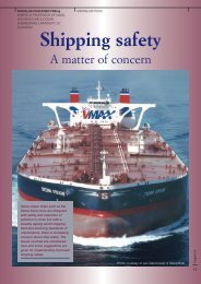
The Øresund Bridge<br />
– linking<br />
Scandinavia<br />
to the<br />
continent<br />
The Øresund Bridge, one of the<br />
largest infrastructure projects in<br />
the history of Europe, is set to<br />
change southern Scandinavia forever.<br />
A combined tunnel and bridge link<br />
carrying the motorway and railway has<br />
replaced the existing ferry routes<br />
between the Danish capital of<br />
Copenhagen and the Swedish regional<br />
capital of Malmö.<br />
The Øresund Bridge comprises three<br />
major civil works projects: a 4 km<br />
artificial island, the world’s largest<br />
immersed tunnel for both railway and<br />
motorway, as well as the 7.8 km bridge<br />
with a cable-stayed high bridge as the<br />
impressive centrepiece.<br />
Almost five years after the civil works<br />
began the Øresund Bridge was opened<br />
to traffic on 1 July 2000. This 3 billion<br />
USD project was completed on<br />
schedule as well as on budget.<br />
The new and greatly improved<br />
infrastructure will further the integration<br />
of the area now known as the Øresund<br />
Region, a cross-border region with<br />
roughly 3.5 million Danish and Swedish<br />
inhabitants. Combining the best of<br />
Copenhagen and Malmö, the Øresund<br />
Region will have a major impact on<br />
Northern Europe in terms of education,<br />
science, finance and culture. But<br />
before full integration can be achieved,<br />
a substantial amount of legislation has<br />
to be introduced, not least within the<br />
labour market and education.<br />
ingenia<br />
23
INFRASTRUCTURE<br />
Figure 2: The route of the Øresund Bridge<br />
ingenia<br />
The skill with which the contractors<br />
successfully planned and executed the<br />
construction of the tunnel, the bridge<br />
and the major dredging works can<br />
largely be ascribed to the Design-and-<br />
Construct concept which forms a part<br />
of all the major contracts. Optimum use<br />
of prefabrication also played a key role.<br />
As the Design-and-Construct concept<br />
lays down precise functional<br />
requirements for the whole project,<br />
contractors are responsible for the<br />
detailed design as well as for the<br />
construction work.<br />
Rigorous environmental requirements<br />
were in force throughout the<br />
construction period, governing both the<br />
construction of the link and the impact<br />
of the completed link on the<br />
surrounding environment. As the Danish<br />
and Swedish governments had<br />
stipulated that the link must not block<br />
the water flow through Øresund, careful<br />
trimming of the link’s design reduced<br />
the calculated blocking effect from 2.3<br />
per cent of the water flow to 0.5 per<br />
cent prior to final adjustment.<br />
Compensation dredging in and around<br />
the alignment further reduced the<br />
blocking effect.<br />
Dredging and reclamation<br />
The dredging and reclamation contract<br />
included the initial construction works<br />
for the fixed link which began in August<br />
1995. Over four years a total of 7.5<br />
million cubic metres of (mainly) seabed<br />
material was dredged, two thirds in<br />
Danish waters and one third in Swedish<br />
waters. The seabed consists of gravel<br />
and stone, clay till and limestone with<br />
flint layers.<br />
Dredging was carried out by a<br />
number of dredgers, traditional bucket<br />
dredgers as well as a specialised<br />
cutter/suction dredger for the tunnel<br />
trench.<br />
The objective was for the<br />
completed link to have no net effect<br />
on the water flow and on the<br />
movement of salt and dissolved<br />
oxygen through Øresund to the Baltic<br />
Sea. Consequently the size and shape<br />
of the peninsula and the island were<br />
optimised to reduce the blocking of<br />
the water flow through Øresund.<br />
Further reduction to zero blocking was<br />
achieved by compensation dredging.<br />
All dredged seabed material was<br />
reused in the reclaimed areas which<br />
cut sediment spill to a minimum and,<br />
in addition, reduced the need for<br />
dumping sites as well as for import of<br />
sand and gravel.<br />
The dredging works included:<br />
● Work harbours and access channels<br />
at the artificial island and the artificial<br />
peninsula<br />
24
INFRASTRUCTURE<br />
● A trench for the immersed tunnel<br />
● Relocation of the Drogden Channel<br />
● Relocation and deepening of the<br />
Flinte Channel<br />
● Compensation dredging to achieve<br />
zero blocking of the water flow<br />
The reclamation works included:<br />
● The artificial peninsula at Kastrup<br />
● The artificial island which connects<br />
the tunnel and the bridge<br />
The 0.9 km 2 peninsula at Kastrup<br />
serves to bring together the passenger<br />
track from the underground station at<br />
Kastrup Airport with the freight track<br />
running north of the airport. The<br />
motorway along the northern edge of<br />
the peninsula joins the railway at the<br />
entrance to the tunnel portal. The<br />
peninsula also has a track leading to a<br />
railway maintenance area.<br />
The 1.3 km 2 artificial island south of<br />
the natural island of Saltholm forms the<br />
transition between the tunnel and the<br />
bridge. From the tunnel portal on the<br />
western end of the island, the motorway<br />
runs parallel to the railway to the eastern<br />
end, from where the railway runs under<br />
the motorway on to the two level bridge.<br />
The reclamation areas were<br />
constructed as basins surrounded by<br />
coarse pebble bunds lined with a<br />
geotextile membrane. The basins were<br />
then backfilled with clay to prevent the<br />
suspended sediment from escaping.<br />
Reclamation was carried out in stages<br />
as the bunds were completed,<br />
surrounding the individual sections.<br />
During filling at the artificial island, the<br />
traffic corridor for the high-speed<br />
railway was compacted to minimise any<br />
differential settlements which could<br />
interfere with the passage of highspeed<br />
trains. The reclaimed areas were<br />
completed with revetments, comprising<br />
layers of armour stones and filter<br />
stones. The revetments protect the<br />
tunnel against flooding during storms<br />
and high water.<br />
The immersed tunnel<br />
The tunnel extends approximately 4 km<br />
from the Danish coast at Copenhagen<br />
Airport to the artificial island in the<br />
middle of Øresund. The tunnel<br />
comprises five parallel tunnel tubes –<br />
two for the railway, two for the<br />
motorway plus a small tunnel as an<br />
escape gallery. The sheer size of the<br />
tunnel and the shallow waters in this<br />
part of Øresund made an immersed<br />
tunnel the natural choice.<br />
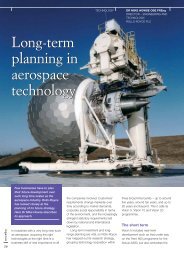
Figure 3: Aerial view of tunnel factory<br />
ingenia<br />
25
INFRASTRUCTURE<br />
ingenia<br />
26<br />
Figure 4: Aerial view of tunnel section being towed to site<br />
The immersed tunnel was<br />
constructed from twenty prefabricated<br />
concrete tunnel elements. The elements<br />
were cast at a purpose-built factory 12<br />
km north of the tunnel site. Each<br />
element was towed to the tunnel site by<br />
four tug boats and lowered into the<br />
tunnel trench with enormous precision,<br />
using GPS satellite navigation.<br />
The fact that casting took place<br />
under cover allowed for efficient and<br />
smooth production, regardless of the<br />
weather. As a positive side effect the<br />
number of work-related accidents was<br />
subsequently reduced.<br />
Each tunnel element is 176 metres<br />
long, 49 metres wide, approximately 9<br />
metres high and weighs around 57,000<br />
tonnes. Each element was cast in eight<br />
sections at the tunnel factory each of<br />
which was cast in one 30 hour cycle.<br />
Each section was cast against the<br />
previous section and the element was<br />
then gradually pushed out of the<br />
casting hall and on to a ramp, in what<br />
was, in effect, a giant lock system.<br />
When all eight sections were cast and<br />
one complete 176 metre element was<br />
ready, a sliding gate was closed behind<br />
the element, and the basin was flooded<br />
until the element floated.<br />
The element could then be pulled<br />
into the deep end of the basin to await<br />
being towed to the tunnel site. After the<br />
water inside the lock had reached sea<br />
level allowing the element to be towed<br />
out, the next two elements would be<br />
cast. Two parallel production lines<br />
allowed for maximum output and<br />
efficiency.<br />
The towing of the elements<br />
demanded great skill and precision. The<br />
57,000 tonne element was almost<br />
completely immersed during towing<br />
and the changing currents in Øresund<br />
had to be calculated in great detail<br />
before the towing-out. This operation<br />
took place in the Drogden Channel in<br />
Western Øresund, which is an<br />
international shipping route used by<br />
some 40,000 ships per year. Early in<br />
the construction phase a radar station<br />
was established to monitor shipping<br />
and guide vessels through the work<br />
areas thus avoiding any major<br />
accidents. During operations only a<br />
handful of collisions and minor incidents<br />
took place involving work vessels and<br />
shipping, causing material damage only.<br />
Not once was a tunnel element<br />
damaged due to a collision. However,<br />
on 4 August 1998, the accident that<br />
everybody was dreading took place: a<br />
tunnel element was flooded while being<br />
positioned in the tunnel trench. Before<br />
tow-out the tunnel tubes in the element<br />
were sealed off with steel bulkheads.<br />
Due to a number of mistakes one<br />
bulkhead was not properly secured and<br />
succumbed to the water pressure. In a<br />
matter of seconds all five tunnel tubes<br />
in the large concrete element filled with<br />
water, and in accordance with<br />
procedures the element was<br />
immediately lowered into the trench,<br />
but several metres out of position. It<br />
took Øresund Tunnel Contractors eight<br />
weeks to inspect, repair and eventually<br />
move the tunnel element into its correct<br />
position.<br />
During this period the lowering gear<br />
and platforms were attached to the<br />
flooded element so the contractor was<br />
unable to save time simply by building<br />
the tunnel from both sides at the same<br />
time. However the tunnel factory<br />
continued to produce the tunnel<br />
elements and once the flooded tunnel<br />
element had been repaired and placed<br />
in the correct position, the tow-out and<br />
construction of the rest of the tunnel<br />
elements was carried out at high<br />
speed. As a result, despite this major<br />
setback, the tunnel was constructed<br />
ahead of schedule.<br />
The Bridge<br />
For the bridge section, which connects<br />
the artificial island with the Swedish<br />
coast at Lernacken, a cable-stay<br />
design was chosen for the high bridge<br />
due to the weight of the combined<br />
railway and motorway link. The entire<br />
bridge is 7.8 km long of which the high<br />
bridge accounts for 1,092 metres. The
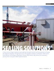
INFRASTRUCTURE<br />
Figure 5: Floating crane carrying deck section<br />
The cables of the high bridge are<br />
arranged in a classic harp pattern and<br />
anchored to the superstructure truss at<br />
20 metre intervals. Supported primarily<br />
on two pairs of pillar shafts the bridge is<br />
symmetrical from the centre of the<br />
navigation span. It has intermediate<br />
side span piers to limit the deflections<br />
of the 490 metre main span. Each<br />
pylon consists of twin, cast-in-situ<br />
concrete towers extending to a height<br />
of 204 metres above sea level. Cables<br />
are anchored in the pylons at 12 metre<br />
intervals. The foundations for both the<br />
pylons and the side span piers are<br />
prefabricated concrete caissons,<br />
located in the hard limestone, 14 to 17<br />
metres below sea level.<br />
490 metre long main span of the high<br />
bridge crosses the Flinte navigational<br />
channel, which is used by<br />
approximately 10 per cent of the<br />
vessels passing through Øresund. The<br />
majority of shipping passes through the<br />
Drogden navigational channel along the<br />
Danish coast.<br />
As was the case with the tunnel, a<br />
high level of prefabrication was used in<br />
the construction of the bridge. Apart<br />
from the pylons which were cast in situ,<br />
all other components – caissons, pillar<br />
shafts and bridge girders – were<br />
produced on land and transported to<br />
the bridge by the large floating crane,<br />
the ‘Svanen’. This self-propelled crane,<br />
a unique and highly versatile tool,<br />
positioned the heaviest concrete<br />
caissons and pillar shafts with great<br />
precision. For two years ‘Svanen’ made<br />
regular trips between Sundlink<br />
Contractors’ bridge factory in Malmö<br />
North Harbour and the bridge line,<br />
constructing the two approach bridges<br />
and the high bridge like a giant Lego kit.<br />
The superstructure of the bridge is a<br />
composite steel-concrete structure with<br />
truss girders. The upper deck carries<br />
the motorway and the lower deck<br />
contains the railway. The bridge is the<br />
largest of its kind in the world carrying<br />
both passenger trains, freight trains and<br />
motorway traffic.<br />
Figure 6: View of completed bridge from sea level looking towards tower<br />
ingenia<br />
27
INFRASTRUCTURE<br />
approach bridges were produced by<br />
Dragados in Cadiz in Southern Spain<br />
and subsequently towed to Sweden in<br />
pairs, complete with concrete<br />
motorway deck.<br />
The high bridge is carried by a total<br />
of 80 pairs of cables, ten in each<br />
direction from each pylon leg. Each<br />
cable consists of between 68 and 73<br />
strands. A strand consists of seven 5<br />
mm wires. The wires are galvanised,<br />
waxed and encased in plastic casing.<br />
Each cable has a tensile strength of<br />
2,000 tonnes and the combined length<br />
of all cables is about 25 km. The total<br />
weight is about 2,300 tonnes.<br />
Following the inauguration of the<br />
Øresund Fixed Link on 1 July 2000<br />
approximately 500,000 vehicles<br />
crossed the Øresund Bridge during the<br />
first month. Information about traffic<br />
and toll prices etc. can be seen at<br />
www.oeresundsbron.com. The photo<br />
files of the Øresund Bridge are available<br />
at www.bridgephoto.dk. ■<br />
ingenia<br />
28<br />
Figure 7: Side view of bridge to show cable pattern<br />
With a height of 204 metres above<br />
sea level the pylons of the Øresund<br />
Bridge are the tallest concrete<br />
structures in Sweden. The construction<br />
of the pylons began with the placing of<br />
the pylon caissons which had been<br />
cast in a dry dock in Malmö Harbour<br />
and towed to the bridge line. On top of<br />
the caissons the casting of the pylons<br />
was carried out by means of selfclimbing<br />
formwork. The entire casting<br />
process took seven to ten days for<br />
each 4 metre lift.<br />
About 4,335 m 3 of concrete went<br />
into each pylon leg – 220 m 3 per lift in<br />
the first stage and about 34 m 3 per lift<br />
near the top. The concrete was<br />
provided from a batching plant on a<br />
barge moored next to the pylon<br />
cofferdam. Each pylon leg required 800<br />
tonnes of reinforcement which was<br />
prepared in prefabricated cages, and<br />
then lifted into position. The pentagon<br />
shaped pylon legs are solid for the first<br />
17 metres and hollow above that level.<br />
The reinforcement cages for the<br />
cross beams, which connect the pylon<br />
legs approximately 45 metres above<br />
sea level, were built ashore, then lifted<br />
into position for casting. Steel anchor<br />
boxes were also cast into the pylon<br />
legs, to which the cables are attached.<br />
The eight bridge girders for the high<br />
bridge were produced at Karlskrona<br />
shipyard on the East coast of Sweden<br />
and then towed to Malmö, where the<br />
concrete motorway deck was added.<br />
The forty-nine girders for the two<br />
Main contractors on the<br />
Øresund Bridge<br />
Dredging and Reclamation<br />
Öresund Marine Joint Venture:<br />
● Per Aarselff (DK)<br />
● Ballast Nedam Dredging (NL)<br />
● Great Lakes Dredge and Dock<br />
Co. (USA)<br />
The Tunnel<br />
Øresund Tunnel Contractors:<br />
● NCC International (SE)<br />
● Dumez-GTM International (F)<br />
● John Laing (UK)<br />
● E. Pihl & Søn (DK)<br />
● Boskalis Westminster Dredging<br />
(NL)<br />
The Bridge<br />
Sundlink Contractors:<br />
● Skanska (SE)<br />
● Højgaard & Schultz (DK)<br />
● Monberg & Thorsen (DK)<br />
● Hochtief (D)<br />
The Railway<br />
Banverket Industridivisionen (SE)