passive and active compensations for current transformers - Agir
passive and active compensations for current transformers - Agir
passive and active compensations for current transformers - Agir

Create successful ePaper yourself
Turn your PDF publications into a flip-book with our unique Google optimized e-Paper software.
SINTEZE<br />
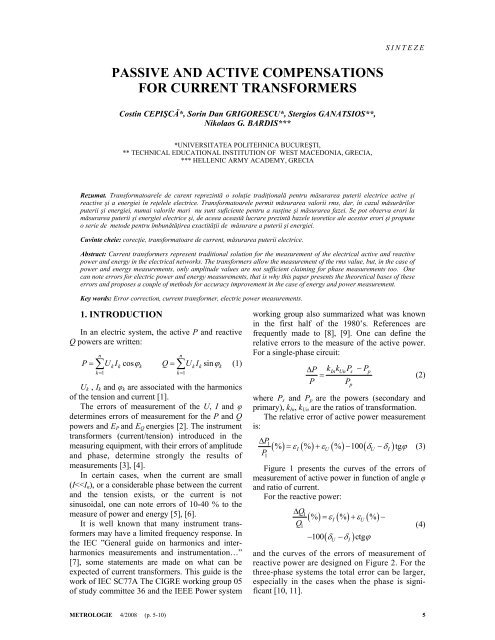
PASSIVE AND ACTIVE COMPENSATIONS<br />
FOR CURRENT TRANSFORMERS<br />
Costin CEPIŞCĂ*, Sorin Dan GRIGORESCU*, Stergios GANATSIOS**,<br />
Nikolaos G. BARDIS***<br />
*UNIVERSITATEA POLITEHNICA BUCUREŞTI,<br />
** TECHNICAL EDUCATIONAL INSTITUTION OF WEST MACEDONIA, GRECIA,<br />
*** HELLENIC ARMY ACADEMY, GRECIA<br />
Rezumat. Trans<strong>for</strong>matoarele de curent reprezintă o soluţie tradiţională pentru măsurarea puterii electrice <strong>active</strong> şi<br />
re<strong>active</strong> şi a energiei în reţelele electrice. Trans<strong>for</strong>matoarele permit măsurarea valorii rms, dar, în cazul măsurărilor<br />
puterii şi energiei, numai valorile mari nu sunt suficiente pentru a susţine şi măsurarea fazei. Se pot observa erori la<br />
măsurarea puterii şi energiei electrice şi, de aceea această lucrare prezintă bazele teoretice ale acestor erori şi propune<br />
o serie de metode pentru îmbunătăţirea exactităţii de măsurare a puterii şi energiei.<br />
Cuvinte cheie: corecţie, trans<strong>for</strong>matoare de <strong>current</strong>, măsurarea puterii electrice.<br />
Abstract: Current trans<strong>for</strong>mers represent traditional solution <strong>for</strong> the measurement of the electrical <strong>active</strong> <strong>and</strong> re<strong>active</strong><br />
power <strong>and</strong> energy in the electrical networks. The trans<strong>for</strong>mers allow the measurement of the rms value, but, in the case of<br />
power <strong>and</strong> energy measurements, only amplitude values are not sufficient claiming <strong>for</strong> phase measurements too. One<br />
can note errors <strong>for</strong> electric power <strong>and</strong> energy measurements, that is why this paper presents the theoretical bases of these<br />
errors <strong>and</strong> proposes a couple of methods <strong>for</strong> accuracy improvement in the case of energy <strong>and</strong> power measurement.<br />
Key words: Error correction, <strong>current</strong> trans<strong>for</strong>mer, electric power measurements.<br />
1. INTRODUCTION<br />
In an electric system, the <strong>active</strong> P <strong>and</strong> re<strong>active</strong><br />
Q powers are written:<br />
n<br />
P= ∑UkIk cosϕk<br />
k = 1<br />
n<br />
Q= ∑ U I sinϕ<br />
(1)<br />
k = 1<br />
k k k<br />
U k , I k <strong>and</strong> φ k are associated with the harmonics<br />
of the tension <strong>and</strong> <strong>current</strong> [1].<br />
The errors of measurement of the U, I <strong>and</strong> φ<br />
determines errors of measurement <strong>for</strong> the P <strong>and</strong> Q<br />
powers <strong>and</strong> E P <strong>and</strong> E Q energies [2]. The instrument<br />
trans<strong>for</strong>mers (<strong>current</strong>/tension) introduced in the<br />
measuring equipment, with their errors of amplitude<br />
<strong>and</strong> phase, determine strongly the results of<br />
measurements [3], [4].<br />
In certain cases, when the <strong>current</strong> are small<br />
(I
Costin CEPIŞCĂ, Sorin Dan GRIGORESCU, Stergios GANATSIOS, Nikolaos G. BARDIS<br />
Fig. 3. MATLAB-SIMULINK model <strong>for</strong> the <strong>current</strong><br />
trans<strong>for</strong>mer.<br />
Fig. 1. The relative error of <strong>active</strong> power measurement.<br />
The results of simulations are presented in<br />
Figure 4 which shoes the predicted results proving<br />
large increase of errors, bought in phase angle <strong>and</strong><br />
ratio, <strong>for</strong> <strong>current</strong>s less than a quarter of the nominal<br />
value.<br />
Fig. 2. Errors of measurement on the<br />
electrical re<strong>active</strong> power.<br />
Presence of errors in various ranges imposes<br />
specialized solutions <strong>and</strong> circuits <strong>for</strong> error reduction.<br />
In the literature are showed different solutions <strong>for</strong><br />
<strong>passive</strong> <strong>and</strong> <strong>active</strong> compensation of <strong>current</strong> trans<strong>for</strong>mers<br />
errors. Passive compensation is related<br />
with trans<strong>for</strong>mers constructive type <strong>and</strong> offers<br />
limited solutions over the input magnitude range<br />
<strong>and</strong> frequency response. However circuits implied<br />
in this case, due to their <strong>passive</strong> behavior, do not<br />
generally reduce the reliability of the system.<br />
The <strong>active</strong> systems are more responsive <strong>for</strong><br />
large input value span <strong>and</strong> frequency, but because<br />
of their <strong>active</strong> principle, they claim an additional<br />
energy supply <strong>and</strong> may reduce the overall stability<br />
<strong>and</strong> reliability.<br />
2. UNCERTAINTY OF THE CURRENT<br />
TRANSFORMER. NUMERICAL MODEL<br />
STUDY<br />
The block diagram of the MATLAB-SIMULINK<br />
software is presented in Figure 3, [12].<br />
a)<br />
b)<br />
Fig. 4. Errors of the <strong>current</strong> trans<strong>for</strong>mer:<br />
a – angle error; b – ratio error.<br />
To explain the frequency response of ordinary<br />
<strong>current</strong> trans<strong>for</strong>mers the equivalent circuit diagram<br />
of Figure 5 are most often used [13].<br />
6<br />
METROLOGIE 4/2008
PASSIVE AND ACTIVE COMPENSATIONS FOR CURRENT TRANSFORMERS<br />
Fig. 5. Model <strong>for</strong> <strong>current</strong> trans<strong>for</strong>mer<br />
at medium frequencies.<br />
These are common equivalent diagrams of a<br />
trans<strong>for</strong>mer except <strong>for</strong> the capacitors. The capacitors<br />
C 1 <strong>and</strong> C 2 are the lumped stray capacitance of the<br />
primary <strong>and</strong> secondary winding, respectively, <strong>and</strong><br />
C 12 is the stray capacitance between the windings.<br />
At low frequencies such as 50 Hz they may be<br />
negligible but <strong>for</strong> higher frequencies they may <strong>for</strong>m<br />
several resonance circuits, together with the leakage<br />
<strong>and</strong> burden reactance, at various frequencies.<br />
From Figure 5, it can further be deducted that<br />
grounding (that affects the voltage across C 12 )<br />
as well as the loading (including long cables),<br />
especially inductive or capacitive loading, may<br />
well affect the frequency response.<br />
In some situations, the equivalent circuit<br />
diagram of Figure 5 may be reduced to the circuit<br />
diagram according to Figure 6.<br />
Fig. 6. Simplified model.<br />
corresponds to the ratio of real trans<strong>for</strong>mation (k I )<br />
<strong>and</strong> it is related to parameters L, l ,ω, R’= R + r<br />
(Figure 8). The perfect conditions <strong>for</strong> a <strong>current</strong><br />
trans<strong>for</strong>mer are: inductance L has an infinite value,<br />
the values of l <strong>and</strong> R’ negligible.<br />
– the phase response:<br />
R + r<br />
Θ = arctan (6)<br />
ω L + ωl<br />
Fig. 8. Errors in the measurement of <strong>active</strong> power<br />
due to H ( ω ) .<br />
The phase Θ is the image of the phase between<br />
the primary <strong>current</strong> <strong>and</strong> the <strong>current</strong> on resistance<br />
R’. The evolution of Θ according to L, l, ω <strong>and</strong> R’<br />
has paces obtained by calculation (Figure 9).<br />
Inductance L influences much more the phase; a<br />
low value increases Θ. The inductance l must be<br />
limited. The resistance of the shunt R must be low.<br />
Let us analyze the propagation of the errors<br />
affecting the measurement of power <strong>and</strong> energy<br />
one can use a simply model of <strong>current</strong> trans<strong>for</strong>mer-<br />
Figure 7.<br />
Fig. 7. Model of <strong>current</strong> trans<strong>for</strong>mer.<br />
One can determine easily the frequency response<br />
H(jω):<br />
– the amplitude response:<br />
H<br />
( ω)<br />
2<br />
2<br />
ωL<br />
( R + r)<br />
+ ( ωL<br />
+ ωl)<br />
= (5)<br />
2<br />
2<br />
( R + r)<br />
+ ( ωL<br />
+ ωl)<br />
Fig. 9. Errors occurring in the measurement<br />
of <strong>active</strong> power due to Θ.<br />
METROLOGIE 4/2008 7
Costin CEPIŞCĂ, Sorin Dan GRIGORESCU, Stergios GANATSIOS, Nikolaos G. BARDIS<br />
The effects of internal parameters of <strong>current</strong><br />
trans<strong>for</strong>mer in the power measurement are presented<br />
in the Figure 10.<br />
chance of unwanted resonance may be considered<br />
a drawback <strong>for</strong> this simple arrangement.<br />
Fig. 12. SIMULINK model <strong>for</strong> <strong>passive</strong> compensation<br />
of <strong>current</strong> trans<strong>for</strong>mer.<br />
Fig. 10. Effects of internal parameters of <strong>current</strong> trans<strong>for</strong>mer<br />
in the power measurement.<br />
3. PASSIVE COMPENSATION METHOD<br />
A correct compensation is carried out only <strong>for</strong><br />
one fixed configuration: type of trans<strong>for</strong>mer, wiring<br />
<strong>and</strong> measuring apparatus [14].<br />
Use a <strong>passive</strong> network (Fig. 11) compensate<br />
errors caused by the inductance trans<strong>for</strong>mer L by<br />
adding a capacitor C.<br />
a) without C: ε I = 8,2 %<br />
δ I = 7,5º;<br />
b) C= 100μF : ε I = 8,0 %<br />
δ I = 6,5º<br />
Fig. 13. Passive compensation results, I 1 = 1% I 1n .<br />
Fig. 11. In circuit <strong>passive</strong> compensation basics.<br />
In Figure 12 is shown the MATLAB-SIMULINK<br />
model <strong>for</strong> the circuit in Figure 11. The results of<br />
compensation <strong>for</strong> small <strong>current</strong> are presented in<br />
Figure 13. One may see that errors reduction in<br />
small bought <strong>for</strong> ratio <strong>and</strong> phase angle. No<br />
shortage in reliability, due of the insertion of the<br />
capacitor, is the main schematic advantage, but the<br />
4. ACTIVE COMPENSATION<br />
METHOD<br />
The <strong>active</strong> compensation uses <strong>active</strong> circuits, i.e.<br />
operational amplifier based, in various schematics.<br />
The principle proposed in this article is illustrated<br />
in Figure 13, [15]. No additional windings on<br />
the <strong>current</strong> trans<strong>for</strong>mer are used, making the circuit<br />
an add on device <strong>for</strong> the actual field trans<strong>for</strong>mers.<br />
8<br />
METROLOGIE 4/2008
PASSIVE AND ACTIVE COMPENSATIONS FOR CURRENT TRANSFORMERS<br />
Fig. 14. Active<br />
compensation<br />
schematic.<br />
Fig. 16. Experimental rig.<br />
Using SPICE simulation of the electronic circuit<br />
in Figure 14, angle error results are presented in<br />
Figure 15.a <strong>for</strong> nominal <strong>current</strong> I 1n <strong>and</strong> Figure 15.b<br />
<strong>for</strong> a <strong>current</strong> as low as 5% I 1n .<br />
The following wave<strong>for</strong>ms were acquired using<br />
an acquisition system based on a HP- digital<br />
sampling oscilloscope, <strong>and</strong> prove predicted results<br />
into the DSO error limits. An example of input/output<br />
<strong>current</strong>s is illustrated on the DSO – Figure 17.<br />
Fig. 17. Input <strong>and</strong> output wave<strong>for</strong>ms<br />
acquired by the DSO.<br />
a) Θ =0,00736°<br />
In practice low <strong>current</strong>s, with respect to I 1n ,<br />
errors behavior is important, that this domain was<br />
extensively explored. The following results are<br />
obtained <strong>for</strong> a primary <strong>current</strong> of 20%I 1n . In<br />
Figure 18 are illustrated the wave<strong>for</strong>ms in the<br />
actual case of a burden reduced with 50%, <strong>and</strong> in<br />
Figure 19 are the correspondent results <strong>for</strong> a burden<br />
increased ten times. No actual differences may be<br />
observed in the bought limit cases <strong>for</strong> the aspect of<br />
the main wave<strong>for</strong>ms.<br />
b) Θ =0,00738°<br />
Fig. 15. Angle error <strong>for</strong> simulated circuit in Figure 14.<br />
5. EXPERIMENTAL ASPECTS<br />
FOR ACTIVE COMPENSATION<br />
The implemented instrument using trans<strong>for</strong>mers<br />
<strong>active</strong> compensation is illustrated in Figure 16 <strong>for</strong> a<br />
100 A/5 A ratio trans<strong>for</strong>mer <strong>and</strong> S n = 5 VA.<br />
Fig. 18. Current wave<strong>for</strong>ms in the case of I1=20%I1n,<br />
Z2=50%Z2n.<br />
METROLOGIE 4/2008 9
Costin CEPIŞCĂ, Sorin Dan GRIGORESCU, Stergios GANATSIOS, Nikolaos G. BARDIS<br />
0.2<br />
0.15<br />
0.1<br />
0.05<br />
0<br />
-0.05<br />
-0.1<br />
-0.15<br />
-0.2<br />
0 0.02 0.04 0.06 0.08 0.1<br />
I1 - verde, I2 - rosu<br />
Fig. 19. Current wave<strong>for</strong>ms in the case of I 1 =20%I 1n ,<br />
Z 2 =10Z 2n ,<br />
The experimental results indicate an accurate<br />
behavior of the proposed circuit even on edge conditions<br />
of extra large burden values.<br />
6. CONCLUSIONS<br />
The measuring equipment of the electric power,<br />
with <strong>current</strong> trans<strong>for</strong>mers presents errors due to the<br />
specific condition (phase, the shape of the <strong>current</strong>,<br />
amplitude of the <strong>current</strong>). This analysis explains<br />
the sources of errors <strong>and</strong> the possibilities of compensation<br />
of uncertainties.<br />
Two methods of <strong>passive</strong> <strong>and</strong> <strong>active</strong> errors compensation<br />
are proposed in this article. Each<br />
method presents advantages <strong>for</strong> the metrological<br />
characteristics <strong>and</strong> drawbacks from the point of<br />
view of global reliability <strong>and</strong> functional side effects.<br />
The <strong>active</strong> compensation has superior metrological<br />
per<strong>for</strong>mances, but implying the use of additional<br />
electronics <strong>and</strong> power supplies may eventually<br />
reduce the overall reliability of the system.<br />
Scientific Bulletin of The National Session of the Scientific<br />
Community, Third Edition, p. 241-250, 16-17 November<br />
2000, Brasov, Romania<br />
[7] *** IEC, (1991), Electromagnetic compatibility (EMC)-<br />
Part 4: Testing <strong>and</strong> measurement techniques section 7:<br />
General guide on harmonics <strong>and</strong> interharmonics measurements<br />
<strong>and</strong> instrumentation, <strong>for</strong> power supply systems<br />
<strong>and</strong> equipment <strong>and</strong> equipment connected thereto.<br />
[8] ***IEC, (1978), International Electrotechnical vocabulary<br />
- chapter 131: Electric <strong>and</strong> magnetic circuits<br />
[9] Hsu, S.P, Middlebrook, P R.D., Cuk, S., Trans<strong>for</strong>mer<br />
modeling <strong>and</strong> design <strong>for</strong> leakage control, Advances in<br />
Switched–Mode Power conversion, Volumes I & II<br />
[10] Dogaru, V, Cepişcă, C, Andrei, H, Contribution Concerning<br />
the LabVIEW Simulation of the Electric<br />
Trans<strong>for</strong>mer, WSEAS Transactions on Circuits <strong>and</strong><br />
Systems, Issue 8, volume 5, August 2006, ISSN 1109-<br />
2734, pp.1361-1365<br />
[11] Ferrero, A., Furga-Superti, G., A, New approach to the<br />
definition of power components in three-phase systems<br />
under non-sinusoidal conditions, IEEE Transactions on<br />
Instrumentation <strong>and</strong> Measurement, Vol.40, No. 3, pp<br />
568-577, 1991<br />
[12] Cepişcă, C, Seriţan, G, Ganatsios, S, Jula, N, Andrei, H,<br />
Méthodes de correction des erreurs dues aux trans<strong>for</strong>mateurs<br />
de courant au mesurage des énergies<br />
électriques, 3-rd International Conference on Electrical<br />
<strong>and</strong> Power Engineering “EPE 2004”, October 8, 2004,<br />
Iaşi, vol. B, pp 749-755.<br />
[13] Larry Meares, L., Hymowitz, C., Improved Spice model<br />
simulates trans<strong>for</strong>mers physical processes, EDN, August 19,<br />
1993.<br />
[14] Cepişcă, C, Grigorescu, S, Andrei, H, Jula, N, The study<br />
of metrological per<strong>for</strong>mances of <strong>current</strong> trans<strong>for</strong>mers,<br />
Proceedings of 3rd International Conference “Metrology-<br />
Measurement Systems”, METSIM 2005, september, 22-<br />
23, 2005, Bucharest.<br />
[15] Grigorescu, S, Cepişcă, C, Trans<strong>for</strong>mator de măsurare<br />
compensat electronic, Proceedings of International Symposium<br />
“ Advanced Measurement Methods”, June 22, 2006,<br />
Bucharest, Session II Sensors Technology <strong>and</strong> Signals,<br />
pp.56-60, Editura PRINTEC.<br />
REFERENCES<br />
[1] Cepişcă, C, ş.a., Electrical energy measurement (roumanian),<br />
Ed. ICPE, Bucuresti, 2001<br />
[2] Ţugulea, A., Power-flows under non-sinusoidal <strong>and</strong> nonsymmetric<br />
periodic <strong>and</strong> almost periodic steady-states of<br />
electrical power systems, 6 th International Conference on<br />
Harmonics in Power Systems, Bologna , Italy, 1994<br />
[3] Becaud,C., Yang, X., Les erreurs de mesure de la<br />
puissance électrique dues au trans<strong>for</strong>mateur de ourant,<br />
Note de EDF, 1994<br />
[4] Iacobescu, F., Buzac, E, Ionescu, F, Cepişcă, C, Preoccupation<br />
at national level, in Romania, concerning st<strong>and</strong>ardization<br />
in the field of electrical energy, OIML Bulletin, Vol.<br />
LVII, Number 4, October 2006, pp.19-22<br />
[5] Cepişcă, C., Seriţan, G.C., Evaluation of Accuracy of the<br />
Traditional Measurements in Electrical Networks,<br />
Symposium on ATEE, Bucharest, 1998<br />
[6] Cepişcă C., Jula N., Seriţan G.C., Accuracy of the Electrical<br />
Energy Measurement. Errors <strong>and</strong> Compensation Methods,<br />
Scientific revue:<br />
Ion M. POPESCU, professor, Politehnica University<br />
Bucharest.<br />
About authors:<br />
Costin CEPIŞCĂ, professor, doctor at Politehnica<br />
University Bucharest, e-mail: costin@wing.ro<br />
Sorin Dan GRIGORESCU, professor, doctor at<br />
Politehnica University Bucharest, e-mail:<br />
sgrig@electro.masuri.pub.ro<br />
Stergios GANATSIOS, professor, doctor, at Technical<br />
Educational Institution of West Macedonia,<br />
e-mail: ganatsio@teikoz.gr<br />
Nikolaos G. BARDIS, doctor at Hellenic Army<br />
Academy, e-mail: bardis@ieee.org<br />
10<br />
METROLOGIE 4/2008