passive and active compensations for current transformers - Agir
passive and active compensations for current transformers - Agir
passive and active compensations for current transformers - Agir

Create successful ePaper yourself
Turn your PDF publications into a flip-book with our unique Google optimized e-Paper software.
Costin CEPIŞCĂ, Sorin Dan GRIGORESCU, Stergios GANATSIOS, Nikolaos G. BARDIS<br />
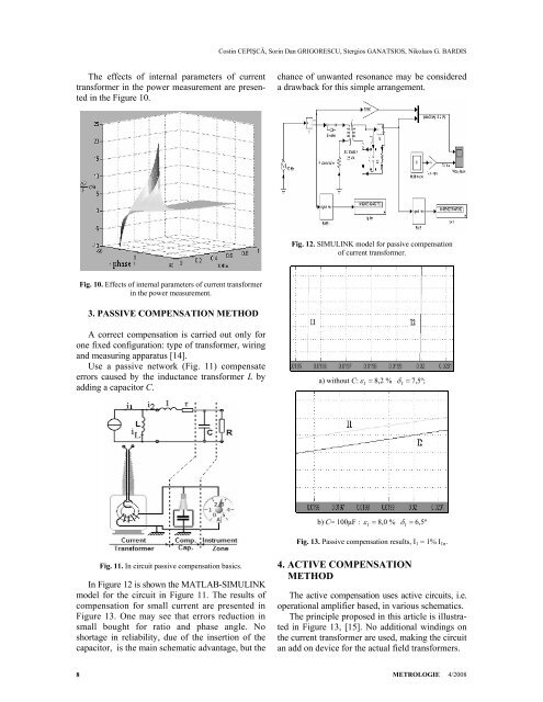
The effects of internal parameters of <strong>current</strong><br />
trans<strong>for</strong>mer in the power measurement are presented<br />
in the Figure 10.<br />
chance of unwanted resonance may be considered<br />
a drawback <strong>for</strong> this simple arrangement.<br />
Fig. 12. SIMULINK model <strong>for</strong> <strong>passive</strong> compensation<br />
of <strong>current</strong> trans<strong>for</strong>mer.<br />
Fig. 10. Effects of internal parameters of <strong>current</strong> trans<strong>for</strong>mer<br />
in the power measurement.<br />
3. PASSIVE COMPENSATION METHOD<br />
A correct compensation is carried out only <strong>for</strong><br />
one fixed configuration: type of trans<strong>for</strong>mer, wiring<br />
<strong>and</strong> measuring apparatus [14].<br />
Use a <strong>passive</strong> network (Fig. 11) compensate<br />
errors caused by the inductance trans<strong>for</strong>mer L by<br />
adding a capacitor C.<br />
a) without C: ε I = 8,2 %<br />
δ I = 7,5º;<br />
b) C= 100μF : ε I = 8,0 %<br />
δ I = 6,5º<br />
Fig. 13. Passive compensation results, I 1 = 1% I 1n .<br />
Fig. 11. In circuit <strong>passive</strong> compensation basics.<br />
In Figure 12 is shown the MATLAB-SIMULINK<br />
model <strong>for</strong> the circuit in Figure 11. The results of<br />
compensation <strong>for</strong> small <strong>current</strong> are presented in<br />
Figure 13. One may see that errors reduction in<br />
small bought <strong>for</strong> ratio <strong>and</strong> phase angle. No<br />
shortage in reliability, due of the insertion of the<br />
capacitor, is the main schematic advantage, but the<br />
4. ACTIVE COMPENSATION<br />
METHOD<br />
The <strong>active</strong> compensation uses <strong>active</strong> circuits, i.e.<br />
operational amplifier based, in various schematics.<br />
The principle proposed in this article is illustrated<br />
in Figure 13, [15]. No additional windings on<br />
the <strong>current</strong> trans<strong>for</strong>mer are used, making the circuit<br />
an add on device <strong>for</strong> the actual field trans<strong>for</strong>mers.<br />
8<br />
METROLOGIE 4/2008