passive and active compensations for current transformers - Agir
passive and active compensations for current transformers - Agir
passive and active compensations for current transformers - Agir

Create successful ePaper yourself
Turn your PDF publications into a flip-book with our unique Google optimized e-Paper software.
PASSIVE AND ACTIVE COMPENSATIONS FOR CURRENT TRANSFORMERS<br />
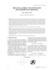
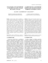
Fig. 14. Active<br />
compensation<br />
schematic.<br />
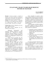
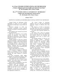
Fig. 16. Experimental rig.<br />
Using SPICE simulation of the electronic circuit<br />
in Figure 14, angle error results are presented in<br />
Figure 15.a <strong>for</strong> nominal <strong>current</strong> I 1n <strong>and</strong> Figure 15.b<br />
<strong>for</strong> a <strong>current</strong> as low as 5% I 1n .<br />
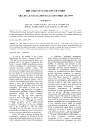
The following wave<strong>for</strong>ms were acquired using<br />
an acquisition system based on a HP- digital<br />
sampling oscilloscope, <strong>and</strong> prove predicted results<br />
into the DSO error limits. An example of input/output<br />
<strong>current</strong>s is illustrated on the DSO – Figure 17.<br />
Fig. 17. Input <strong>and</strong> output wave<strong>for</strong>ms<br />
acquired by the DSO.<br />
a) Θ =0,00736°<br />
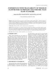
In practice low <strong>current</strong>s, with respect to I 1n ,<br />
errors behavior is important, that this domain was<br />
extensively explored. The following results are<br />
obtained <strong>for</strong> a primary <strong>current</strong> of 20%I 1n . In<br />
Figure 18 are illustrated the wave<strong>for</strong>ms in the<br />
actual case of a burden reduced with 50%, <strong>and</strong> in<br />
Figure 19 are the correspondent results <strong>for</strong> a burden<br />
increased ten times. No actual differences may be<br />
observed in the bought limit cases <strong>for</strong> the aspect of<br />
the main wave<strong>for</strong>ms.<br />
b) Θ =0,00738°<br />
Fig. 15. Angle error <strong>for</strong> simulated circuit in Figure 14.<br />
5. EXPERIMENTAL ASPECTS<br />
FOR ACTIVE COMPENSATION<br />
The implemented instrument using trans<strong>for</strong>mers<br />
<strong>active</strong> compensation is illustrated in Figure 16 <strong>for</strong> a<br />
100 A/5 A ratio trans<strong>for</strong>mer <strong>and</strong> S n = 5 VA.<br />
Fig. 18. Current wave<strong>for</strong>ms in the case of I1=20%I1n,<br />
Z2=50%Z2n.<br />
METROLOGIE 4/2008 9