IRIS - Boiler Tubes Inspection Report - Innospection
IRIS - Boiler Tubes Inspection Report - Innospection
IRIS - Boiler Tubes Inspection Report - Innospection

You also want an ePaper? Increase the reach of your titles
YUMPU automatically turns print PDFs into web optimized ePapers that Google loves.
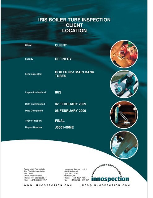
<strong>IRIS</strong> BOILER TUBE INSPECTION<br />
CLIENT<br />
LOCATION<br />
Client<br />
CLIENT<br />
Facility<br />
REFINERY<br />
Item Inspected<br />
BOILER No1 MAIN BANK<br />
TUBES<br />
<strong>Inspection</strong> Method<br />
<strong>IRIS</strong><br />
Date Commenced 02 FEBRUARY 2009<br />
Date Completed 08 FEBRUARY 2009<br />
Type of <strong>Report</strong><br />
<strong>Report</strong> Number<br />
FINAL<br />
J0001-09ME<br />
Sector M-41 Plot 93-94B Howemoss Avenue - Unit 1<br />
Abu Dhabi Industrial City<br />
Kirkhill Industrial<br />
Abu Dhabi<br />
Dyce AB21 0GP<br />
United Arab Emirates<br />
Aberdeen, UK<br />
Phone: +971 (0)2 5500574 Phone: +44 (0) 1224 724 744<br />
Fax: +971 (0)2 5500757 Fax: +44 (0) 1224 774 087<br />
W W W . I N N O S P E C T I O N . C O M<br />
I N F O @ I N N O S P E C T I O N . C O M
CLIENT<br />
<strong>Boiler</strong> No1<br />
Main Bank <strong>Tubes</strong><br />
<strong>IRIS</strong> REPORT<br />
Final <strong>Inspection</strong> <strong>Report</strong><br />
Page<br />
1 of 7<br />
K-No.<br />
J0001-09ME<br />
CONTENT<br />
Page No<br />
1.0 Test Object ............................................................................................................2<br />
2.0 <strong>Inspection</strong> Task......................................................................................................2<br />
3.0 <strong>Inspection</strong> Personnel .............................................................................................3<br />
4.0 Test Equipment......................................................................................................3<br />
5.0 <strong>IRIS</strong> Equipment Setting sensitivity settings ............................................................4<br />
6.0 Calibration Control.................................................................................................5<br />
7.0 Tube Identification .................................................................................................6<br />
9.0 <strong>Inspection</strong> Result ...................................................................................................6<br />
10.0 <strong>Inspection</strong> Result ...................................................................................................6<br />
11.0 Documentation.......................................................................................................9<br />
12.0 Signatures .............................................................................................................9<br />
Appendices<br />
1. Tabulation of all minimum wall thickness.<br />
2. Cross section overview by Row number<br />
3. Cross section overview by Column number (Tube)
CLIENT<br />
<strong>Boiler</strong> No1<br />
Main Bank <strong>Tubes</strong><br />
<strong>IRIS</strong> REPORT<br />
Final <strong>Inspection</strong> <strong>Report</strong><br />
Page<br />
2 of 7<br />
K-No.<br />
J0001-09ME<br />
1.0 Test Object<br />
Item : <strong>Boiler</strong> No 1 Main Bank <strong>Tubes</strong><br />
Material : Carbon Steel<br />
Diameter : 63.5mm swaged to 50.8mm<br />
Wall Thickness :<br />
4.06mm & 5.0mm<br />
Tube Length : 13m – 16m<br />
Quantity : 714<br />
2.0 <strong>Inspection</strong> Task<br />
As per instruction an <strong>IRIS</strong> (Internal Rotary <strong>Inspection</strong> System) inspection was<br />
carried out on the 714 Main Bank tubes as listed in 1.0 above.<br />
The inspection was performed with a computerised TC5800 single Channel<br />
ultrasonic system. All results were recorded to disk with manual analysis conducted<br />
on screen. Calibration was done on the tubing to be inspected. The <strong>IRIS</strong> testing<br />
team consisted of four qualified <strong>IRIS</strong> engineers supplied by <strong>Innospection</strong> Limited.<br />
Purpose of the inspection was to survey for evidence of internal and external<br />
erosion and to determine the integrity of the tubing and to monitor the general<br />
condition of the main bank<br />
3.0 <strong>Inspection</strong> Personnel<br />
<strong>Innospection</strong> Technician: Frederik Bothma <strong>IRIS</strong> Level 2.<br />
<strong>Innospection</strong> Technician: Arno Pretorius <strong>IRIS</strong> Level 2.<br />
4.0 Test Equipment<br />
<strong>IRIS</strong> Unit : RD Tech Multiscan MS5800U.<br />
Software : Multiview 6.0R4<br />
Data Storage : Laptop Hard Drive<br />
4.1 Concept of <strong>IRIS</strong><br />
Back wall<br />
Front wall
CLIENT<br />
<strong>Boiler</strong> No1<br />
Main Bank <strong>Tubes</strong><br />
<strong>IRIS</strong> REPORT<br />
Final <strong>Inspection</strong> <strong>Report</strong><br />
Page<br />
3 of 7<br />
K-No.<br />
J0001-09ME<br />
45 ° angled mirror<br />
Transducer<br />
Unlike eddy current, remote field and magnetic flux leakage, that operate on magnetic or<br />
electromagnetic principles the <strong>IRIS</strong>, technique is based on Ultrasonic’s. As shown in the<br />
above illustration a beam from an ultrasonic transducer is reflected from a mirror set at 45<br />
degrees so that the reflected ultrasonic beam impinges on the tube I.D. at right angles. Part<br />
of this beam is then reflected from the tube I.D., while the remainder is transmitted through<br />
the wall thickness and is reflected from the tube O.D. The time difference between the two<br />
reflected signals is then used to measure the tube wall thickness. The mirror is mounted on<br />
a water driven turbine that rotates at a speed of about 2 000 rpm. Measurements are then<br />
made around the full tube circumference and as the probe head is pulled through the tube<br />
the ultrasonic beam maps out a spiral along the tube length. If the probe pulling speed is<br />
sufficiently slow, taking into account the inspection parameters, 100 % coverage of the tube<br />
surface is achieved. With advanced software results can be displayed in a number of views<br />
as illustrated below<br />
The C-scan presentation provides a plan view of the tube when it has been rolled flat.<br />
Colour-coding is used to display the wall thickness as illustrated by the rainbow of Colours<br />
displayed in the icon in the right hand bottom corner of Fig. 2. The B-scan display provides<br />
a 2 dimensional display of a transverse cut through the tube at any desired position along<br />
the tube length, while the D-scan display provides a 2 dimensional display of a longitudinal<br />
cut through the tube at any desired circumferential position on the tube
CLIENT<br />
<strong>Boiler</strong> No1<br />
Main Bank <strong>Tubes</strong><br />
<strong>IRIS</strong> REPORT<br />
Final <strong>Inspection</strong> <strong>Report</strong><br />
Page<br />
4 of 7<br />
K-No.<br />
J0001-09ME<br />
4.2 Advantages of <strong>IRIS</strong><br />
a) Very accurate technique. Wall thickness measurements can be made to<br />
accuracy within 0.1mm, with the use of a 15MHz-focused transducer.<br />
b) Fairly sensitive technique. The sensitivity achieved will depend on tube<br />
dimensions and tube cleanliness. In general it can be stated that it should be<br />
possible to detect a 1.5mm defect in up to 1 inch tubing that has been properly<br />
cleaned.<br />
c) A three dimensional picture of the defect is obtained. Thus the defect profile in<br />
addition to its depth is obtained.<br />
d) Interpretation of results is easier than in the other techniques assuming that<br />
acceptable tube cleanliness has been achieved.<br />
e) Ferromagnetic and non-ferromagnetic tubes can be inspected.<br />
4.3 Disadvantages of <strong>IRIS</strong><br />
a) It is a slow technique. The actual testing speed will depend on a number of factors, but<br />
will generally be of the order of 0.04m/sec. to achieve 100% coverage. However it<br />
must be noted that the tube has to be filled with water (couplant) every time prior to the<br />
actual inspection. This will reduce the typical production rates to be in the order of +/-<br />
100 tubes per 12-hour shift. Although this will depend on the tube length and number<br />
of units being inspected as well as the cleanliness of the tubes and the water pressure<br />
supplied at the point of inspection.<br />
b) <strong>Tubes</strong> must be very clean. While all the other techniques can tolerate some degree of<br />
scaling, tubes must be cleaned virtually down to bare metal for a successful <strong>IRIS</strong><br />
inspection.<br />
c) Water must be introduced into the tube to act as a couplant. At times this can be a<br />
problem due to no suitable water outlet being available at the point of inspection. In<br />
other cases the source of water may not be clean enough or may not be at the ambient<br />
temperature required for a successful inspection. In some cases the introduction of<br />
water into the tubes may give rise to corrosion problems.<br />
d) Only volumetric defects will be detected. It is not, therefore, sensitive to cracking.<br />
5.0 Sensitivity Setting<br />
The general overview of the inspected areas with its results is presented in the<br />
attached colour scan reports, with wall loss represented in colour classes as below:
CLIENT<br />
<strong>Boiler</strong> No1<br />
Main Bank <strong>Tubes</strong><br />
<strong>IRIS</strong> REPORT<br />
Final <strong>Inspection</strong> <strong>Report</strong><br />
Page<br />
5 of 7<br />
K-No.<br />
J0001-09ME<br />
6.0 Calibration Control<br />
The general setting and calibration was performed at the beginning of the inspection<br />
and at the beginning of every shift.<br />
A check of the calibration was done after any larger breaks and or changes in any<br />
equipment. All calibration data is stored digitally.<br />
Calibration samples are used for initial set-up and also for the random check of<br />
operator settings.<br />
7.0 Tube Identification<br />
In order to be able to identify and locate each tube, and thereby create full<br />
traceability the grid coordinates of row & tube were used. The identification of Row 1<br />
is closest to the furnace and <strong>Tubes</strong> are numbered from left to right with Tube1 being<br />
on your left hand side when seated in the stream drum facing the furnace.<br />
8.0 <strong>Inspection</strong> Results<br />
<strong>Tubes</strong> were found to be in a clean condition. The mud drum was sealed off and the<br />
boiler was flooded to the height of the last row of tubes in the steam drum.<br />
Defective tubes were classified in accordance with CTBR specifications<br />
Orange:<br />
Green:<br />
Blue<br />
Pink<br />
Remaining wall thickness between 3.8mm and 4.5mm<br />
Remaining wall thickness between 3.5mm and 3.8mm<br />
Remaining wall thickness between 3.24mm and 3.5mm<br />
Remaining wall thickness between 2.4mm and 3.24mm<br />
Red Remaining wall thickness less than 2.4mm<br />
For analysis the tube were analysed and categorised into meter sections starting<br />
from the Steam Drum with the consensus that the 2 meter mark will be at the top<br />
bend position. A total overview in the form of a tube sheet drawing is shown in<br />
Appendix 1. Recorded minimum wall thickness is given in a tabulated format in
CLIENT<br />
<strong>Boiler</strong> No1<br />
Main Bank <strong>Tubes</strong><br />
<strong>IRIS</strong> REPORT<br />
Final <strong>Inspection</strong> <strong>Report</strong><br />
Page<br />
6 of 7<br />
K-No.<br />
J0001-09ME<br />
Appendix 2 while cross section overviews of Rows & Columns are given in<br />
Appendices 3 & 4 respectively. Below is a short summary of each row inspected.<br />
Row 1<br />
No wastage noted in this row. The first 9 meters of tubing from the Steam drum<br />
have been replaced with 5 mm tubing.<br />
Row 2<br />
Some wastage was detected in the first 6 – 7 meter from the mud drum of this row.<br />
The first 8 meters of tubing from the Steam drum have been replaced with 5 mm<br />
tubing.<br />
Row 3<br />
In tube 40, 3 meter from the steam drum wastage was detected. 41 tubes in this row<br />
have been replaced with 5 mm tubing from the top bend to the 8 meter mark. Tube<br />
32 could not be inspected past the 8m mark due to the weld bead height restricting<br />
the <strong>IRIS</strong> centraliser.<br />
Row 4<br />
No wastage detected in this row. <strong>Tubes</strong> 5 & 6 have been replaced with 5mm tubing<br />
from the 5m mark to the Mud drum. <strong>Tubes</strong> 32 and 40 have been replaced between<br />
the 3 & 8m marks<br />
Row 5<br />
Wastage was found 4 meter from the steam drum in tube 42 and no other wastage<br />
was detected.<br />
Row 6<br />
Seven tubes exhibited slight wastage below the top bend and all tubes had sections<br />
replaced with 5mm tubing.<br />
Row 7<br />
Thirteen tubes exhibited wastage below the top bend another three a both the top<br />
bend. All this wastage was recorded in recently replaced 5mm tubing sections.<br />
Row 8<br />
8 tubes exhibited wastage <strong>Tubes</strong> 47 showed wastage just below the bottom bend.<br />
All tubes have been replaced with 5mm tubing from the 9m mark to the bottom<br />
bend.<br />
Row 9<br />
8 tubes showed an indication of wastage. Five was directly below the 5mm tubing<br />
that that has been inserted in all tubes between the 9 to 11m marks the other three<br />
a both.<br />
Row 10<br />
Only seven tubes had indications of wastage. Two tubes have the wastage<br />
indication a both the top bend at the steam drum the rest was spread between the<br />
two bends<br />
.
CLIENT<br />
<strong>Boiler</strong> No1<br />
Main Bank <strong>Tubes</strong><br />
<strong>IRIS</strong> REPORT<br />
Final <strong>Inspection</strong> <strong>Report</strong><br />
Page<br />
7 of 7<br />
K-No.<br />
J0001-09ME<br />
Row 11<br />
Six tubes had indications of wastage between the 3m from the mud drum up to the<br />
steam drum. The <strong>IRIS</strong> Centraliser could not be passed through the bottom bend of<br />
the tubes due to the angle of the bends<br />
Row 12<br />
Seven tubes had indications of wastage. <strong>Tubes</strong> 2 and 13 was plugged, al the<br />
wastage was found between the two bends<br />
Row 13<br />
Two tubes had indications of wastage in this row. With is situated between the two<br />
bends. The <strong>IRIS</strong> Centraliser could not be passed through the bottom bend of the<br />
tubes due to the angle of the bends.<br />
Row14<br />
Fourteen tubes had indication of wastage. This was mainly between the two bends.<br />
Tube 21 had a minor indication of wastage just a both the bottom bend at the steam<br />
drum. The <strong>IRIS</strong> Centraliser could not be passed through the bottom bend of the<br />
tubes due to the angle of the bends. There was one tube which could not been<br />
inspected and another one only partially.<br />
11 .0 Documentation<br />
This inspection data and report is stored on disk in the <strong>Innospection</strong> Limited<br />
documentation system.<br />
12.0 Signatures<br />
Frederik J. Bothma<br />
<strong>Inspection</strong> Engineer<br />
<strong>Innospection</strong> Limited<br />
Mike Churchill<br />
Senior Engineer<br />
<strong>Innospection</strong> Limited
CLIENT: CLIENT DATE 02-08 FEB 2009<br />
LOCATION: REFINERY REPORT No J0001-09ME<br />
UNIT: BOILER No1 #<br />
5 5 4 4 4 4 4 4 4 4 4 4 3 3 3 3 3 3 3 3 3 3 2 2 2 2 2 2 2 2 2 2 1 1 1 1 1 1 1 1 1 1<br />
1 0 9 8 7 6 5 4 3 2 1 0 9 8 7 6 5 4 3 2 1 0 9 8 7 6 5 4 3 2 1 0 9 8 7 6 5 4 3 2 1 0 9 8 7 6 5 4 3 2 1<br />
2.0 M 2.0 M<br />
3 M 3 M<br />
4 M 4 M<br />
5 M 5 M<br />
6 M 6 M<br />
7 M 7 M<br />
8 M 8 M<br />
9 M 9 M<br />
10 M 10 M<br />
11 M 11 M<br />
12 M 12 M<br />
13.5M 13.5M<br />
NOMINAL WALL<br />
4.50 - 5.60 mm<br />
3.80 - 4.50mm<br />
CROSS SECTION VIEW BY ROW<br />
ROW 02<br />
EROSION DAMAGE<br />
3.8 - 4.5 mm<br />
3.5 - 3.8 mm<br />
3.24 - 3.5 mm<br />
2.4 to 3.24mm<br />
0.1 - 2.4 mm<br />
No Result
CLIENT: CLIENT DATE 02-08 FEB 2009<br />
LOCATION: REFINERY REPORT No J0001-09ME<br />
UNIT: BOILER No1 #<br />
CROSS SECTION VIEW BY COLUMNS<br />
COLUMN 02<br />
1<br />
2<br />
3<br />
4<br />
5<br />
14<br />
13<br />
6<br />
7<br />
8 9<br />
10<br />
12<br />
11<br />
NOMINAL WALL<br />
4.50 - 5.60 mm<br />
3.80 - 4.50mm<br />
EROSION DAMAGE<br />
3.8 - 4.5 mm<br />
3.5 - 3.8 mm<br />
3.24 - 3.5 mm<br />
2.4 to 3.24mm<br />
0.1 - 2.4 mm<br />
No Result<br />
3<br />
2<br />
5<br />
4<br />
6<br />
7<br />
8<br />
9<br />
10<br />
11<br />
1<br />
12<br />
2<br />
13<br />
14
CLIENT: CLIENT DATE: 02-08 FEB 2009<br />
LOCATIONREFINERY REPORT No: J0001-09ME<br />
UNIT: BOILER No1<br />
WALL THICKNESS MEASUREMENT<br />
ROW 02<br />
ROW COL DEFECT<br />
Remaining<br />
wall<br />
Thickness<br />
2 1 ERO 3.68<br />
2 2 ERO 4.03<br />
2 3 ERO 3.89<br />
2 4 ERO 3.92<br />
2 5 ERO 3.45<br />
2 6 ERO 3.3<br />
2 7 ERO 3.56<br />
2 8 ERO 3.68<br />
2 9 ERO 4.06<br />
2 10 ERO 3.68<br />
2 11 ERO 3.56<br />
2 12 ERO 4.01<br />
2 13 ERO 3.98<br />
2 14 ERO 3.59<br />
2 15 ERO 4.12<br />
2 16 ERO 3.92<br />
2 17 ERO 3.71<br />
2 18 ERO 3.24<br />
2 19 ERO 4.01<br />
2 20 ERO 3.74<br />
2 21 ERO 3.89<br />
2 22 ERO 3.39<br />
2 23 ERO 3.98<br />
2 24 ERO 3.95<br />
2 25 ERO 3.83<br />
2 26 ERO 4.01<br />
2 27 ERO 3.53<br />
2 28 ERO 3.86<br />
2 29 ERO 3.98<br />
2 30 ERO 3.68<br />
2 31 ERO 3.62<br />
2 32 ERO 3.83<br />
2 33 ERO 3.71<br />
2 34 ERO 3.39<br />
2 35 ERO 3.89<br />
2 36 ERO 3.77<br />
2 37 ERO 3.74<br />
2 38 ERO 3.95<br />
2 39 ERO 3.95<br />
2 40 ERO 3.86<br />
2 41 ERO 3.8<br />
2 42 ERO 3.83<br />
2 43 ERO 3.5<br />
2 44 ERO 3.95<br />
2 45 ERO 3.45<br />
2 46 ERO 3.95<br />
2 47 ERO 3.92<br />
2 48 ERO 4.01<br />
2 49 ERO 3.45<br />
2 50 ERO 3.71<br />
2 51 ERO 3.98<br />
COMMENTS