fifth wheels - INTERCON Truck Equipment
fifth wheels - INTERCON Truck Equipment
fifth wheels - INTERCON Truck Equipment

Create successful ePaper yourself
Turn your PDF publications into a flip-book with our unique Google optimized e-Paper software.
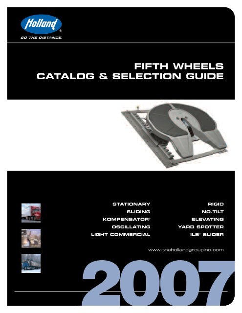
FIFTH WHEELS<br />
CATALOG & SELECTION GUIDE<br />
STATIONARY<br />
RIGID<br />
SLIDING<br />
NO-TILT<br />
KOMPENSATOR ®<br />
ELEVATING<br />
OSCILLATING<br />
YARD SPOTTER<br />
LIGHT COMMERCIAL ILS ® SLIDER<br />
www.thehollandgroupinc.com
TECHNOLOGY<br />
advanced technology delivers superior performance<br />
Holland <strong>fifth</strong> <strong>wheels</strong> have earned a reputation<br />
for exceptional durability, driver productivity<br />
and reliability that continues to “raise the bar”<br />
on <strong>fifth</strong> wheel performance standards while<br />
lowering the total cost-of-ownership.<br />
Revolutionary<br />
Designs<br />
The Holland 3500 model <strong>fifth</strong> wheel has been<br />
the foundation for evolutionary new ideas that<br />
expand <strong>fifth</strong> wheel function and value. For<br />
example, Holland’s 3500 NoLube model<br />
eliminates all <strong>fifth</strong> wheel lubrication<br />
requirements.This advancement means that<br />
drivers no longer get dirty from greasy <strong>fifth</strong><br />
<strong>wheels</strong>. Nor do they spend time greasing top<br />
plates or locks. Shop managers can improve<br />
the work environment for mechanics and<br />
reduce the potential for costly injuries from<br />
slips and falls on greasy floors.And, fleets can<br />
protect the environment from excess grease<br />
on the road on in our water supply.<br />
Other Holland innovations on the 3500 Series<br />
include a system for in-cab air release of the<br />
<strong>fifth</strong> wheel locks, an Electronic Lock Indicator<br />
(ELI) which insures a secure coupling between<br />
tractor and trailer, and the new ILS ® low weight,<br />
integrated sliding <strong>fifth</strong> wheel bracket.<br />
Guaranteed<br />
Performance<br />
Holland has raised the bar on supplier<br />
accountability.We offer the industries first <strong>fifth</strong><br />
wheel “wear-out” guarantee.We call it our<br />
Performance Guarantee. Basically, we<br />
guarantee that your Holland <strong>fifth</strong> wheel will<br />
perform according to our operating<br />
instructions or we will take care of the cost to<br />
repair or replace it. Please see the appropriate<br />
<strong>fifth</strong> wheel warranty statement for further<br />
information.<br />
Innovative Holland <strong>fifth</strong> wheel technology is<br />
the best in the world. Our <strong>fifth</strong> <strong>wheels</strong> offer<br />
proven value and performance in addition to<br />
exceptional operating and economic<br />
advantages.<br />
Warranty<br />
XL-WC118-03<br />
3500 NoLube (FW31) FIFTH WHEEL<br />
COMMERCIAL WARRANTY (North America)<br />
Holland’s Commitment:<br />
We warrant each 3500NoLube<strong>fifth</strong> wheel manufactured<br />
after December 1, 2002, when properly installed on<br />
your vehicle and maintained in accordance with our<br />
requirements, as follows:<br />
I. Materials and Workmanship:<br />
Our 3500 NoLube <strong>fifth</strong> wheel will be free from defects<br />
in material and workmanship for five years or 500,000<br />
miles (whichever comes first). In approved applications,<br />
the lube plates are warranted for two years or 200,000<br />
miles (whichever comes first).<br />
II. Application Specific Performance Guarantee:<br />
In addition, when your3500NoLube<strong>fifth</strong> wheel is used<br />
in Standard Duty Applications (as defined below) it will,<br />
for six years after the date of your purchase or 600,000<br />
miles (whichever comes first):<br />
1. Operate as described in our 3500 NoLube<br />
operation and maintenance literature;<br />
2. Maintain an acceptablewear limit between the<br />
<strong>fifth</strong> wheel locks and a new SAE J700b kingpin<br />
when adjusted in accordance with our 3500<br />
NoLube maintenance literature;<br />
Standard Duty Applications require that your vehicle:<br />
1) operates on-highway only; 2) has a maximum gross<br />
combined vehicle weightof95,000 lbs. (including<br />
tractor, trailer, and cargo); and 3) has a maximum of five<br />
axles; and 4) excludes pick-up and delivery (less than 30<br />
miles between stops) applications.<br />
If any 3500 NoLube <strong>fifth</strong> wheel or component part is<br />
determined to have a defect in material and workmanship<br />
or if it does not perform as warranted in an approved<br />
application, we will cover the cost to repair or replace<br />
the product or part.We will provide a reasonable labor<br />
allowance for removal, and repair or replacement, and<br />
will provide you with parts or reimburse you for parts at<br />
your acquisition cost, provided this does not exceed the<br />
suggested fleet price.<br />
Your Responsibilities:<br />
You are responsible for proper installation, operation and<br />
maintenance as specified in our publications on 3500<br />
NoLube <strong>fifth</strong> <strong>wheels</strong> and for using the product in recommended<br />
applications and capacities.<br />
You are required to obtain prior authorization fromHolland<br />
or an authorized customer service representative before<br />
replacing or returning any part.You may be required to<br />
make the product or part claimed to be covered by this<br />
warranty available to us and/or returned to us for review<br />
and evaluation.<br />
Exclusions and Limitations:<br />
This warranty does not cover any 3500 NoLube<strong>fifth</strong> wheel<br />
or component that fails, malfunctions or is damaged as a<br />
result of accident, abuse, or improper use.<br />
THIS WARRANTYISOUR SOLE WARRANTY IN REGARD<br />
TO COVERED 3500 NOLUBE FIFTH WHEELS. WE MAKE<br />
NO OTHER WARRANTIES, EXPRESS OR IMPLIED, OR<br />
OF MERCHANTABILITY OR FITNESS FOR A PARTICULAR<br />
PURPOSE. IN NO EVENT SHALL WE BE RESPONSIBLE<br />
FOR SPECIAL, INCIDENTAL OR CONSEQUENTIAL<br />
DAMAGESOFANY KIND.
GO THE DISTANCE.<br />
TABLE OF<br />
FIFTH WHEEL CATALOG<br />
CONTENTS<br />
& SELECTION GUIDE<br />
How to Use this Guide . . . . . . . . . . . . . . . . . . . . . . . . . . . . . . . . . . . . . . . . . . . . . . . . . . . 3<br />
Items to Consider Before Selecting Your Fifth Wheel<br />
Fifth Wheel Types (Stationary/Slider). . . . . . . . . . . . . . . . . . . . . . . . . . . . . . . . . . . . . . . . 4<br />
Fifth Wheel Ratings, Capacities, Heights,Weights and Cost. . . . . . . . . . . . . . . . . . . . . . . 5<br />
Fifth Wheel Applications<br />
Applications (By Fifth Wheel Type) . . . . . . . . . . . . . . . . . . . . . . . . . . . . . . . . . . . . . . 6 – 7<br />
Features of Holland Fifth Wheels<br />
Top Plate Assemblies<br />
3500 (FW35) XA-351 Series . . . . . . . . . . . . . . . . . . . . . . . . . . . . . . . . . . . . . . . . . . . 8<br />
FW17 XA-17 Series . . . . . . . . . . . . . . . . . . . . . . . . . . . . . . . . . . . . . . . . . . . . . . . . . . 9<br />
3500 NoLube (FW31) XA-311 Series . . . . . . . . . . . . . . . . . . . . . . . . . . . . . . . . . . . 10<br />
3500 LowLube (FW33) XA-331 Series . . . . . . . . . . . . . . . . . . . . . . . . . . . . . . . . . . 11<br />
FleetMaster (FW8) XA-201 Series . . . . . . . . . . . . . . . . . . . . . . . . . . . . . . . . . . . . . . 12<br />
FleetMaster LowLube (FW83) XA-231 Series . . . . . . . . . . . . . . . . . . . . . . . . . . . . . 13<br />
Extra Capacity (FW0070) XA-71 Series. . . . . . . . . . . . . . . . . . . . . . . . . . . . . . . . . . 14<br />
Stationary Mount Brackets . . . . . . . . . . . . . . . . . . . . . . . . . . . . . . . . . . . . . . . . . . . . . 15<br />
Slide Bracket and Plate Assemblies. . . . . . . . . . . . . . . . . . . . . . . . . . . . . . . . . . . . . . . 16<br />
Heavy Duty Stationary Fifth Wheels<br />
CAPACITY<br />
Max. Vertical Max. Drawbar<br />
Load Pounds Load Pounds<br />
FW0100 Series . . . . . . . . . . . . . . . . . . 100,000 . . . . . . . . . . 200,000 . . . . . . . . . . 17<br />
FW0165 Series . . . . . . . . . . . . . . . . . . 165,000 . . . . . . . . . . 200,000 . . . . . . . . . . 17<br />
Stationary Kompensator ® Fifth Wheels<br />
FW8 Series. . . . . . . . . . . . . . . . . . . . . . 50,000. . . . . . . . . . . 150,000 . . . . . . . . . . 18<br />
FW35 Series (3500). . . . . . . . . . . . . . . 55,000. . . . . . . . . . . 150,000 . . . . . . . . . . 18<br />
FW7040 Series. . . . . . . . . . . . . . . . . . . 70,000. . . . . . . . . . . 200,000 . . . . . . . . . . 19<br />
Oscillating Fifth Wheels<br />
FW1560-B . . . . . . . . . . . . . . . . . . . . . . 40,000. . . . . . . . . . . 150,000 . . . . . . . . . . 20<br />
FW2080 Series. . . . . . . . . . . . . . . . . . . 70,000. . . . . . . . . . . 200,000 . . . . . . . . . . 20<br />
Yard Spotter Fifth Wheels<br />
FW35-03344 Series . . . . . . . . . . . . . . . 70,000 . . . . . . . . . . . . . . . . . . . . . . . . . . . . 21<br />
FW2870-03184 Series. . . . . . . . . . . . . 100,000 . . . . . . . . . . . . . . . . . . . . . . . . . . . 21<br />
FW1560-C . . . . . . . . . . . . . . . . . . . . . . 50,000 . . . . . . . . . . . . . . . . . . . . . . . . . . . . 22<br />
Special Features Fifth Wheels<br />
FW1226 Rigid Type . . . . . . . . . . . . . . . 40,000. . . . . . . . . . . 150,000 . . . . . . . . . . 22<br />
“No-Tilt” Convertible . . . . . . . . . . Depends upon <strong>fifth</strong> wheel selection . . . . . . . . 23<br />
“No-Tilt” Mounting Systems . . . . . . . . . . . . . . . . . . . . . . . . . . . . . . . . . . . . . . . . . . 24<br />
Continued on next page
TABLE OF<br />
CONTENTS<br />
Mov-On Elevating Fifth Wheels<br />
Air Lifts<br />
Lift Capacity<br />
FW6700-16B . . . . . . . . . . . . . . . . . . . . 40,000 . . . . . . . . . . . . . . . . . . . . . . . . . . . . 25<br />
Hydraulic Lifts<br />
Lift Capacity<br />
FW2800-X . . . . . . . . . . . . . . . . . . . . . . 50,000 . . . . . . . . . . . . . . . . . . . . . . . . . . . . 25<br />
FW2900-X . . . . . . . . . . . . . . . . . . . . . . 50,000 . . . . . . . . . . . . . . . . . . . . . . . . . . . . 25<br />
FW2800-5X. . . . . . . . . . . . . . . . . . . . . 100,000 . . . . . . . . . . . . . . . . . . . . . . . . . . . 25<br />
FW2900-5X. . . . . . . . . . . . . . . . . . . . . 100,000 . . . . . . . . . . . . . . . . . . . . . . . . . . . 25<br />
Light Commercial Fifth Wheels<br />
Max. Vertical<br />
CAPACITY<br />
Max. Drawbar<br />
Load Pounds Load Pounds<br />
FW1900 Series . . . . . . . . . . . . . . . . . . . . . . 20,000 . . . . . . . . . . . 40,000 . . . . . . . . . . . 26<br />
FW6000 Series . . . . . . . . . . . . . . . . . . . . . . 12,000 . . . . . . . . . . . 32,000 . . . . . . . . . . . 27<br />
FW0001 Series . . . . . . . . . . . . . . . . . . . . . . 8,000. . . . . . . . . . . . 23,000 . . . . . . . . . . . 27<br />
Accessories for FW1900 and FW6000 Series Fifth Wheels . . . . . . . . . . . . . . . . . . . . . . 28<br />
Air Release Systems<br />
Fifth Wheel Lock Release System . . . . . . . . . . . . . . . . . . . . . . . . . . . . . . . . . . . . . . 29<br />
Application Limitations. . . . . . . . . . . . . . . . . . . . . . . . . . . . . . . . . . . . . . . . . . . . . . . . . 30<br />
Selection Tables<br />
Fifth Wheels for Power Units (Tractors)<br />
A. Van Trailers . . . . . . . . . . . . . . . . . . . . . . . . . . . . . . . . . . . . . . . . . . . . . . . . . . . . 31<br />
B. Tanker and Dry Bulk Trailers . . . . . . . . . . . . . . . . . . . . . . . . . . . . . . . . . . . . . . 32<br />
C. Flatbed, Stretch, and Pole Trailers. . . . . . . . . . . . . . . . . . . . . . . . . . . . . . . . . . . 33<br />
D. End Dump (Framed) Trailers . . . . . . . . . . . . . . . . . . . . . . . . . . . . . . . . . . . . . . 34<br />
E. End Dump (Frameless) Trailers . . . . . . . . . . . . . . . . . . . . . . . . . . . . . . . . . . . . 35<br />
F. Side Dump Trailers . . . . . . . . . . . . . . . . . . . . . . . . . . . . . . . . . . . . . . . . . . . . . . 36<br />
G. Bottom Dump Trailers . . . . . . . . . . . . . . . . . . . . . . . . . . . . . . . . . . . . . . . . . . . 37<br />
H. Lowboy Trailers . . . . . . . . . . . . . . . . . . . . . . . . . . . . . . . . . . . . . . . . . . . . . . . . 38<br />
Fifth Wheels for Converter Dollies . . . . . . . . . . . . . . . . . . . . . . . . . . . . . . . . . . . . . . . . 39<br />
Fifth Wheels for B-Trains<br />
A. Van, Flatbed and Stretch Trailers . . . . . . . . . . . . . . . . . . . . . . . . . . . . . . . . . . . 40<br />
B. Tanker and Bottom Dump Trailers . . . . . . . . . . . . . . . . . . . . . . . . . . . . . . . . . . 40<br />
C. End Dump Trailers . . . . . . . . . . . . . . . . . . . . . . . . . . . . . . . . . . . . . . . . . . . . . . 41<br />
Fifth Wheels for Light Commercial Trailers . . . . . . . . . . . . . . . . . . . . . . . . . . . . . . . . . . 41<br />
Popular Options for Fifth Wheels . . . . . . . . . . . . . . . . . . . . . . . . . . . . . . . . . . . . . . . 42<br />
Custom Service Tools for Fifth Wheels. . . . . . . . . . . . . . . . . . . . . . . . . . . . . . . . . . . 43<br />
Fifth Wheel Location and Installation . . . . . . . . . . . . . . . . . . . . . . . . . . . . . . . 44 – 49<br />
Glossary . . . . . . . . . . . . . . . . . . . . . . . . . . . . . . . . . . . . . . . . . . . . . . . . . . . . . . . . . . . 50 – 53<br />
2
HOW TO USE<br />
THIS GUIDE<br />
The Holland Fifth Wheel Selection Guide is set up to help you quickly complete the <strong>fifth</strong> wheel<br />
selection process. Simply complete Steps 1 through 7 below, and you will be well on your way<br />
to placing an order for the correct <strong>fifth</strong> wheel for your vehicle.<br />
Step 1<br />
Step 2<br />
Review “Items to Consider Before Selecting Your Fifth Wheel”<br />
Section: Stationary/Sliding, Ratings and Capacities, Height,<br />
Weight, Cost.<br />
Determine the type of vehicle your <strong>fifth</strong> wheel will be mounted<br />
on (for example, tractor, converter dolly, or B-train connection)<br />
and the type of trailer your <strong>fifth</strong> wheel will be connected to (for<br />
example, van, tanker, etc.).<br />
Step 3<br />
Use the table on Page 31 to determine whether your vehicle will<br />
be used in a Standard, Moderate or Severe Duty application.<br />
Step 4<br />
Locate your vehicle and trailer type in the “Selection Tables”<br />
section of the Table of Contents, and turn to the appropriate<br />
<strong>fifth</strong> wheel selection page (for example, <strong>fifth</strong> <strong>wheels</strong> for tractors<br />
pulling dry bulk trailers are found on Page 31).<br />
Step 5 Refer to the appropriate application as determined in Step 3<br />
and using the vehicle descriptions and expected capacity<br />
requirements, review the series and types of <strong>fifth</strong> <strong>wheels</strong><br />
recommended.<br />
Step 6<br />
After selecting the <strong>fifth</strong> wheel type that meets your requirements,<br />
refer to your Holland <strong>fifth</strong> wheel sales literature for specific part<br />
number and ordering information.This literature is available<br />
from any Holland distributor or dealer or directly from Holland.<br />
Step 7<br />
If there is still insufficient information on which to make a<br />
selection, contact your Holland representative for assistance. In<br />
the U.S., call 1-888-396-6501. In Canada, call 519-537-2366. For a<br />
complete listing of all Holland USA and Holland Canada facilities,<br />
see the back cover of this guide.<br />
3
ITEMS TO CONSIDER<br />
BEFORE SELECTING YOUR FIFTH WHEEL<br />
In addition to selecting the proper <strong>fifth</strong> wheel model for your<br />
application, the following additional items must be considered before<br />
you specify your complete <strong>fifth</strong> wheel assembly:<br />
Stationary or Sliding<br />
Stationary<br />
Stationary <strong>fifth</strong> <strong>wheels</strong> are best suited for applications where the 1) axle<br />
loading, 2) kingpin setting, and 3) vehicle combination length all remain<br />
constant throughout the fleet. Stationary <strong>fifth</strong> <strong>wheels</strong> are generally lighter<br />
weight and lower in cost than sliding <strong>fifth</strong> <strong>wheels</strong>; however, they do not<br />
offer the application flexibility of a sliding <strong>fifth</strong> wheel.<br />
If a stationary <strong>fifth</strong> wheel is chosen, the user still must determine<br />
whether to use an “angle-on-frame” (low cost and less torsional rigidity,<br />
see Figure 1), a “plate mount” (higher cost and high torsional rigidity,<br />
see Figure 2) or an “outboard angle mount” (universal hole pattern for<br />
medium torsional rigidity bolt-on mounting, see Figure 3).This selection<br />
should be made to compliment the suspension and tractor frame.<br />
Sliding<br />
The selection of a sliding <strong>fifth</strong> wheel (see Figures 4 - 6) provides the<br />
capability to 1) transfer weight between tractor axles, 2) accommodate<br />
trailers with different kingpin settings and, 3) vary vehicle combination<br />
lengths.A sliding <strong>fifth</strong> wheel also provides the following additional<br />
benefits:<br />
4<br />
Resale: A sliding <strong>fifth</strong> wheel offers maximum equipment flexibility<br />
and is more likely to fit the application of a prospective purchaser.<br />
Improved Maneuverability: A sliding <strong>fifth</strong> wheel positioned forward<br />
provides additional maneuverability in tight locations and sliding the<br />
<strong>fifth</strong> wheel rearward accommodates trailers with short landing gear<br />
clearance.<br />
Ride Comfort: Driver comfort is increased as the <strong>fifth</strong> wheel is<br />
located closer to the centerline of the bogie or rear axle.When the<br />
axles are not overloaded, the driver has the ability to extend the unit<br />
for maximum comfort.<br />
If a sliding <strong>fifth</strong> wheel is chosen, the mounting style (“outboard angle”<br />
“inboard angle” or “direct mount”) (see Figures 4 - 6) and slide length<br />
must be specified:<br />
Slide Length: Proper slide length specification is very important. If<br />
the slide length is too short, optimum equipment utilization may not<br />
be achieved (i.e. inability to shift enough kingpin load to the front<br />
axle). However, if too long a slide length is specified, either<br />
overloading of the front axle or interference between the<br />
tractor/trailer may occur during cornering.A slide length which is<br />
too long also results in additional tractor weight and <strong>fifth</strong> wheel<br />
initial cost.<br />
Figure 1<br />
Figure 2<br />
Figure 3<br />
Figure 4<br />
Figure 5<br />
Figure 6<br />
Angle on<br />
Frame<br />
Plate<br />
Mount<br />
Outboard<br />
Angle<br />
Mount<br />
Outboard<br />
Angle<br />
Mount<br />
Inboard<br />
Angle<br />
Mount<br />
Direct<br />
Mount
ITEMS TO CONSIDER<br />
BEFORE SELECTING YOUR FIFTH WHEEL<br />
Fifth Wheel Ratings and<br />
Capacities<br />
The selection of the proper <strong>fifth</strong> wheel capacity is<br />
a major consideration. The use of a <strong>fifth</strong> wheel that<br />
does not meet the required capacity and the<br />
demands of the application may result in an unsafe<br />
operating condition and maintenance problems.<br />
The user should specify a higher capacity rating<br />
than his normal needs require, taking into<br />
consideration the towed vehicle weight (TVW) to<br />
be pulled, maximum drawbar load expected,<br />
vertical load to be carried by the <strong>fifth</strong> wheel and<br />
type of operation. Off-highway use will normally<br />
require a higher capacity rating. For example, a<br />
tractor pulling a 130,000 GTW trailer, with a<br />
50,000 lbs. vertical load for off-road use, should be<br />
specifying a HOLLAND extra capacity, stationary<br />
mount FW0070 <strong>fifth</strong> wheel which has a drawbar<br />
capacity of 200,000 lbs. and a vertical load<br />
capacity of 70,000 lbs.<br />
Note: The lower the <strong>fifth</strong> wheel height, the less<br />
articulation available, especially in off-road<br />
applications. Operating conditions must be<br />
considered to ensure the tractor-trailer will not<br />
exceed the available articulation, resulting in<br />
damage to the <strong>fifth</strong> wheel, tractor frame or trailer.<br />
Fifth Wheel Weight<br />
The weight of the <strong>fifth</strong> wheel should be a balance<br />
between operational cost, strength, and durability.<br />
Any additional weight (above the requirements of<br />
your operation) will result in additional expense.<br />
This expense will be in initial cost, reduced cargo<br />
carrying capacity, and additional fuel cost.<br />
Purchasing the lightest <strong>fifth</strong> wheel, however, may<br />
not result in the lowest cost. Lighter weight may<br />
be a trade-off of strength and durability and can<br />
result in additional maintenance, downtime, and<br />
expense.<br />
Fifth Wheel Height<br />
Another item to specify while selecting a <strong>fifth</strong><br />
wheel is the <strong>fifth</strong> wheel height.This is a critical<br />
specification because the overall combination<br />
height cannot exceed 13´ 6˝. The <strong>fifth</strong> wheel is<br />
designed to operate with the top plate level, so<br />
every attempt should be made to match the <strong>fifth</strong><br />
wheel height with the trailer upper coupler<br />
(bolster plate) height.<br />
An important consideration relative to <strong>fifth</strong> wheel<br />
height is developing a standard fleet specification.<br />
Having all tractors with the same mounted <strong>fifth</strong><br />
wheel height (height from the ground to the top<br />
of the <strong>fifth</strong> wheel) will reduce the need to adjust<br />
the trailer landing gear before coupling and<br />
consequently aid in proper coupling.<br />
The maximum allowable <strong>fifth</strong> wheel height is<br />
determined by subtracting the trailer height and<br />
tractor frame height from the maximum height of<br />
13´ 6˝. As a final check, the tire clearance should<br />
be considered, keeping in mind spring deflection<br />
under full load.<br />
Cost<br />
No discussion of <strong>fifth</strong> <strong>wheels</strong> is complete without<br />
referring to costs.The user should always balance<br />
the cost of the unit to be purchased against the<br />
job required, maintenance costs, wear life, and<br />
availability of parts and service.The purchase of an<br />
inexpensive <strong>fifth</strong> wheel may result in additional<br />
operational and repair costs related to downtime<br />
and potential kingpin replacement and tractor or<br />
trailer frame damage which can far exceed the<br />
initial cost of a premium <strong>fifth</strong> wheel.<br />
If a specialty <strong>fifth</strong> wheel (e.g. a Kompensator ® ) or<br />
special options have been recommended for your<br />
application, special consideration should be given<br />
to those recommendations. The benefits received<br />
may offset the additional initial cost.<br />
Also, if your vehicle is expected to serve in<br />
multiple applications, a <strong>fifth</strong> wheel that will<br />
adequately perform all functions should be chosen.<br />
5
FIFTH WHEEL<br />
APPLICATIONS<br />
Semi-Oscillating Type<br />
The standard over-the-road <strong>fifth</strong> wheel is the semi-oscillating<br />
type (See Figure 1) which oscillates or articulates about an<br />
axis perpendicular to the vehicle centerline to accommodate<br />
for normal road variations (inclines, bumps, etc.)<br />
Vehicle<br />
Centerline<br />
NoLube<br />
An over-the-road semi-oscillating <strong>fifth</strong> wheel (See Figure 2)<br />
model designed to completely eliminate all lubrication<br />
requirements. Patented surface alloy on the kingpin contact<br />
surfaces of the lock jaws provide lubrication-free operation,<br />
eliminating the need to grease the locks. Molded “lube free”<br />
inserts in the top plate and “lube free” pocket inserts also<br />
eliminate the need for lubrication.<br />
Figure 1<br />
Top Plate, Brackets & Lock Grease Required<br />
Figure 2<br />
NoLube – No Greasing Required<br />
LowLube<br />
An over-the-road semi-oscillating <strong>fifth</strong> wheel (See Figure 3)<br />
designed to eliminate the use of grease on the top plate and<br />
between top plate and bracket. Grease is supplied to the lock<br />
jaws through an easily accessed lube fitting near the release<br />
handle. Routine maintenance and lubrication of the locking<br />
mechanism is still required. Molded “lube free” inserts in the<br />
top plate and “lube free” pocket inserts eliminate the need for<br />
lubrication in these areas.<br />
Fully (Double) Oscillating Fifth Wheel<br />
A <strong>fifth</strong> wheel designed to provide both front-to-rear<br />
and side-to-side oscillation between the tractor and<br />
semi-trailer; for vehicles that operate on rough and<br />
uneven terrain (mining, logging, etc.) (See Figure 4).<br />
The oscillation is provided by the use of an<br />
undercarriage employing both transverse and<br />
longitudinal shafts.The side-to-side oscillation pivot<br />
point is located below the <strong>fifth</strong> wheel bearing surface.<br />
It is intended for applications where the center<br />
of gravity of the loaded semi-trailer is at or<br />
below the top of the <strong>fifth</strong> wheel.<br />
Front-to-Rear<br />
Oscillation<br />
Figure 3<br />
LowLube – Requires Only Lock Greasing<br />
Figure 4<br />
Vehicle<br />
Centerline<br />
Side-to-Side<br />
Oscillation<br />
6
FIFTH WHEEL<br />
APPLICATIONS<br />
Rigid Type or “No-Tilt”<br />
A rigid <strong>fifth</strong> wheel does not oscillate about either axis of<br />
the vehicle but is fixed in location (Figure 5). In<br />
applications which require this type of <strong>fifth</strong> wheel, the<br />
oscillation (articulation) is provided by other means (i.e.<br />
articulating upper coupler).The no-tilt convertible<br />
(Figure 6) can be converted from a rigid or “no-tilt”<br />
configuration to a standard semi-oscillating configuration<br />
for fleets with mixed trailers and needs for both types.<br />
Figure 5<br />
Rigid Type<br />
Kompensator ® Type<br />
This <strong>fifth</strong> wheel is designed to provide both front-to-rear<br />
and side-to-side oscillation between the tractor and<br />
semi-trailer (See Figure 7).The Kompensator <strong>fifth</strong> wheel<br />
relieves the twisting force between the tractor and<br />
trailer. This configuration has its effective side-to-side<br />
oscillation pivot point located well above the <strong>fifth</strong> wheel<br />
bearing surface (See Figure 8). It is intended for<br />
applications where the center of gravity of the loaded<br />
semi-trailer does not exceed 44˝ above the top surface<br />
of the <strong>fifth</strong> wheel. Benefits include improved tire life and<br />
a reduction in tractor, trailer, and tank cracks. Ideal<br />
applications include rigid trailers (tanker, etc.) operated<br />
on uneven and rough terrain.<br />
Figure 6<br />
No-Tilt Convertible<br />
Mov-On ® Type (Elevating Fifth Wheels)<br />
Figure 7<br />
Kompensator<br />
This <strong>fifth</strong> wheel is designed to convert a standard road<br />
tractor for low cost, efficient yard spotting, switching<br />
and hauling. These <strong>fifth</strong> <strong>wheels</strong> are available in air<br />
(Figure 9) or hydraulic (Figure 10) lift.<br />
5°<br />
Pivot Point<br />
5°<br />
Figure 8<br />
Figure 9 Figure 10<br />
7
TOP PLATES<br />
FIFTH WHEEL<br />
TOP PLATE MODELS<br />
3500 (FW35)<br />
XA-351 Series<br />
Capacity:<br />
55,000 lbs. Maximum Vertical Load<br />
150,000 lbs. Maximum Drawbar Pull<br />
Models Available:<br />
Stationary Kompensator ®<br />
Sliding No-Tilt<br />
Warranty:<br />
• Materials and workmanship: 6 years or 600,000 miles<br />
• Performance Guarantee: 6 years or 600,000 miles<br />
See 3500 Series Fifth Wheel North American<br />
Commercial Warranty for details<br />
Machined top plate to yoke fit-up<br />
area maximizes surface contact<br />
for extended service life.<br />
One step rear<br />
lock provides<br />
high coupling<br />
protection.<br />
Forged steel split lock style.<br />
Rear lock is machined and<br />
heat treated. Provides greater<br />
lock and lock pin durability.<br />
Induction hardened<br />
solid tip yoke is<br />
machined for<br />
extended service life.<br />
Infinite lock adjustment<br />
positions provide improved<br />
lock and kingpin durability.<br />
Front lock combines cast steel top<br />
plate and forged steel lock design.<br />
Both surfaces are machined and heat<br />
treated for extended life.<br />
Lock adjustment nut is<br />
readily accessible providing<br />
ease of maintenance.<br />
Bracket pin design allows<br />
for easy top plate removal<br />
and installation, reducing<br />
maintenance time.<br />
Cast steel top plate is machined<br />
flat, providing a greater load<br />
bearing area to reduce friction<br />
and uneven wear.<br />
Lock provides 7.46 sq. in.<br />
kingpin contact area.<br />
Drop release handle requires<br />
minimum effort and protects<br />
from damage during a<br />
missed couple. Available in<br />
left or right hand release.<br />
Front lock contact area<br />
(3.725 sq in)<br />
Rear lock contact area<br />
(3.730 sq in)<br />
8
TOP PLATES<br />
FIFTH WHEEL<br />
TOP PLATE MODELS<br />
FW17<br />
XA-17 Series<br />
Capacity:<br />
50,000 lbs. Maximum Vertical Load<br />
150,000 lbs. Maximum Drawbar Pull<br />
Models Available:<br />
Stationary<br />
Sliding<br />
Warranty:<br />
• Materials and workmanship: 5 years or 500,000 miles<br />
• Performance Guarantee: 5 years or 500,000 miles<br />
See FW17 Fifth Wheel North American Commercial<br />
Warranty for details<br />
Cast-in grease<br />
grooves keep<br />
grease where it<br />
is needed.<br />
Greater kingpin contact area<br />
(up to 87% more). Provides<br />
longer kingpin and lock life.<br />
A cast steel top plate provides<br />
optimum combination of<br />
durability and low weight.<br />
High coupling lock system<br />
protects against coupling<br />
at an improper height.<br />
Rear lock is forged, hardened<br />
and machined steel. Front<br />
lock is machined, hardened<br />
cast steel.<br />
Patent pending lock<br />
adjustment system makes<br />
the adjustment process<br />
simple and readily accessible.<br />
Lock system combines a cast<br />
steel top plate and forged<br />
steel lock design to provide<br />
maximum durability.<br />
Drop release handle requires<br />
minimum effort and protects from<br />
damage during a missed couple.<br />
Patent pending lock<br />
design provides high<br />
couple protection and<br />
improved safety.<br />
Austempered ductile iron pocket<br />
inserts fit between the top plate<br />
and brackets to provide smooth,<br />
long lasting top plate articulation.<br />
Patent pending release<br />
mechanism utilizes lever<br />
arm design to minimize<br />
pull effort required.<br />
Patent pending release<br />
mechanism provides<br />
automatic secondary lock<br />
to ensure safe operation.<br />
9
TOP PLATES<br />
FIFTH WHEEL<br />
TOP PLATE MODELS<br />
3500 NoLube (FW31)<br />
XA-311 Series<br />
Holland has pioneered the application of advanced coating technologies<br />
in the development of our NoLube <strong>fifth</strong> wheel product line. After<br />
exhaustive investigation, we have selected coating technologies that<br />
combine low friction, long wear life, and corrosion resistance.<br />
Capacity:<br />
55,000 lbs. Maximum Vertical Load<br />
150,000 lbs. Maximum Drawbar Pull<br />
Models Available:<br />
Stationary Sliding Kompensator ®<br />
Lock system components are protected<br />
with a low friction coating which provides<br />
long wear life and corrosion protection.<br />
Warranty:<br />
• Materials and workmanship: 6 years or 600,000 miles<br />
• Performance Guarantee: 6 years or 600,000 miles<br />
• Lube Plates: 2 years or 200,000 miles<br />
See 3500 NoLube Fifth Wheel North American<br />
Commercial Warranty for details<br />
Infinite lock adjustment<br />
positions provide improved<br />
lock and kingpin durability.<br />
Lock adjustment nut is readily<br />
accessible providing ease of<br />
maintenance.<br />
Coated for superior corrosion<br />
resistance, the drop release<br />
handle requires minimum effort<br />
and protects from damage during<br />
a missed couple. Available in left<br />
or right hand release.<br />
Bracket pin design allows for easy<br />
top plate removal and installation,<br />
reducing maintenance time.<br />
The replaceable lube plate inserts<br />
are mechanically-bound to a unique<br />
“perforated” plate that provides<br />
friction-free performance and extends<br />
the life of the lube plate compound.<br />
The lube plates fit into cast recesses<br />
of the top plate and are secured by<br />
studs and locknuts.<br />
Pocket inserts fit between the top<br />
plate and brackets to provide long<br />
lasting top plate articulation.<br />
Patented surface alloy on<br />
the kingpin contact surfaces<br />
of the lock jaws provides<br />
lubrication-free operation<br />
along with corrosion and<br />
wear resistance.<br />
10
TOP PLATES<br />
FIFTH WHEEL<br />
TOP PLATE MODELS<br />
3500 LowLube (FW33)<br />
XA-331 Series<br />
Capacity:<br />
55,000 lbs. Maximum Vertical Load<br />
150,000 lbs. Maximum Drawbar Pull<br />
Models Available:<br />
Stationary Kompensator ®<br />
Sliding<br />
Warranty:<br />
• Materials and workmanship: 6 years or 600,000 miles<br />
• Performance Guarantee: 6 years or 600,000 miles<br />
• Lube Plates: 2 years or 200,000 miles<br />
See 3500 LowLube Fifth Wheel North American<br />
Commercial Warranty for details<br />
Infinite lock adjustment<br />
positions provide<br />
improved lock and<br />
kingpin durability.<br />
Machined top plate to yoke fit-up<br />
area maximizes surface contact<br />
for extended service life.<br />
One step rear<br />
lock provides<br />
high coupling<br />
protection.<br />
Forged steel split lock style.<br />
Rear lock is machined and<br />
heat treated. Provides greater<br />
lock and lock pin durability.<br />
Front lock combines cast steel top plate and<br />
forged steel lock design. Both surfaces are<br />
machined and heat-treated for extended life.<br />
Induction hardened<br />
solid tip yoke is<br />
machined for<br />
extended service life.<br />
Lock adjustment nut is<br />
readily accessible providing<br />
ease of maintenance.<br />
The innovative, replaceable<br />
patented lube plate inserts are<br />
made of non-abrasive material and<br />
molded to a steel backing plate for<br />
greater durability. They fit into cast<br />
recesses of the top plate and are<br />
secured by studs and locknuts.<br />
Drop release handle requires<br />
minimum effort and protects<br />
from damage during a missed<br />
couple. Available in left or right<br />
hand release.<br />
Grease fitting<br />
and tube<br />
provides easy<br />
lubrication of<br />
locks.<br />
Bracket pin design allows for easy<br />
top plate removal and installation,<br />
reducing maintenance time.<br />
Lock provides<br />
7.46 sq. in.<br />
kingpin<br />
contact area.<br />
Austempered ductile iron pocket<br />
inserts fit between the top plate<br />
and brackets to provide smooth,<br />
long lasting top plate articulation.<br />
11
TOP PLATES<br />
FIFTH WHEEL<br />
TOP PLATE MODELS<br />
FleetMaster (FW8)<br />
XA-201 Series<br />
Capacity:<br />
50,000 lbs. Maximum Vertical Load<br />
150,000 lbs. Maximum Drawbar Pull<br />
Models Available:<br />
Stationary Kompensator ®<br />
Sliding<br />
Warranty:<br />
• Materials and workmanship: 5 years or 500,000 miles<br />
• Performance Guarantee: 5 years or 500,000 miles<br />
See FleetMaster Fifth Wheel North American<br />
Commercial Warranty for details<br />
Cast in grease<br />
grooves.<br />
Greater kingpin contact area<br />
(7.2 sq. in.). Provides longer<br />
kingpin and lock life.<br />
Forged steel, machined and<br />
heat treated rear lock with<br />
heat treated cast steel front<br />
lock. Lock hardness is 321-<br />
388 BHN.<br />
Cast steel top plate machined<br />
flat. Provides greater load<br />
bearing area. Reduces friction<br />
and uneven wear.<br />
Drop release handle requires<br />
minimum effort and protects<br />
from damage during a<br />
missed couple. Available in<br />
left or right hand release.<br />
Easy to remove top plate<br />
incorporates new easier<br />
to remove bracket pin.<br />
Lightest weight <strong>fifth</strong> wheel<br />
in the industry. Top plate<br />
weighs only 217 lbs.<br />
Easily accessible lock<br />
adjustment is infinitely<br />
adjustable throughout<br />
the <strong>fifth</strong> <strong>wheels</strong> life.<br />
Lock notch<br />
behind rib<br />
Release handle also<br />
serves as a visual<br />
lock indicator.<br />
Drop handle configuration<br />
is standard. Reduces<br />
handle damage due to<br />
improper coupling.<br />
12
TOP PLATES<br />
FIFTH WHEEL<br />
TOP PLATE MODELS<br />
FleetMaster LowLube (FW83)<br />
XA-231 Series<br />
Capacity:<br />
50,000 lbs. Maximum Vertical Load<br />
150,000 lbs. Maximum Drawbar Pull<br />
Models Available:<br />
Stationary Kompensator ®<br />
Sliding<br />
Warranty:<br />
• Materials and workmanship: 5 years or 500,000 miles<br />
• Performance Guarantee: 5 years or 500,000 miles<br />
• Lube Plates: 2 years or 200,000 miles<br />
See FleetMaster LowLube Fifth Wheel North American<br />
Commercial Warranty for details<br />
Greater kingpin contact area<br />
(7.2 sq. in.). Provides longer<br />
kingpin and lock life.<br />
Forged steel, machined and<br />
heat treated rear lock with<br />
heat treated cast steel front<br />
lock. Lock hardness is 321-<br />
388 BHN.<br />
The innovative, replaceable patented lube plate<br />
inserts are made of non-abrasive material and<br />
molded to a steel backing plate for greater<br />
durability. They fit into cast recesses of the top<br />
plate and are secured by studs and locknuts.<br />
Easy lubrication of locks<br />
provided by grease<br />
fitting and tube.<br />
Easily accessible lock<br />
adjustment is infinitely<br />
adjustable throughout<br />
the <strong>fifth</strong> <strong>wheels</strong> life.<br />
Lock notch<br />
behind rib<br />
Release handle also serves<br />
as a visual lock indicator.<br />
Drop release handle requires<br />
minimum effort and protects<br />
from damage during a<br />
missed couple. Available in<br />
left or right hand release.<br />
Easy to remove cast steel<br />
top plate incorporates easier<br />
to remove bracket pin.<br />
Drop handle<br />
configuration is<br />
standard. Reduces<br />
handle damage<br />
due to improper<br />
coupling.<br />
Austempered ductile iron pocket<br />
inserts fit between the top plate<br />
and brackets to provide smooth,<br />
long lasting top plate articulation.<br />
13
TOP PLATES<br />
FIFTH WHEEL<br />
TOP PLATE MODELS<br />
Extra Capacity (FW0070)<br />
XA-71 Series<br />
Capacities:<br />
FW2555 Sliding Series<br />
62,500 lbs. Maximum Vertical Load<br />
150,000 lbs. Maximum Drawbar Pull<br />
5<br />
1<br />
3<br />
4<br />
2<br />
FW2570 Sliding Series<br />
70,000 lbs. Maximum Vertical Load<br />
150,000 lbs. Maximum Drawbar Pull<br />
FW0070 Stationary Series<br />
70,000 lbs. Maximum Vertical Load<br />
200,000 lbs. Maximum Drawbar Pull<br />
TYPE “A”<br />
LOCKING SYSTEM<br />
1 Swinging Lock<br />
2 Front Lock<br />
3 Plunger<br />
Locks require only<br />
300 lbs. to couple.<br />
Available for 2˝ or<br />
3.5˝ SAE kingpins.<br />
4 Adjusting Wedge<br />
5 Plunger<br />
Cast in grease<br />
grooves.<br />
Cast top plate machined<br />
flat. Provides greater load<br />
bearing area. Reduces<br />
friction and uneven wear.<br />
Grease fittings<br />
lubricate <strong>fifth</strong><br />
wheel bracket<br />
contact area.<br />
Easy to remove<br />
top plate.<br />
Easily accessible slack<br />
adjustment is infinitely<br />
adjustable throughout<br />
its adjustment range.<br />
Manual<br />
secondary lock.<br />
14
MOUNTING SYSTEMS<br />
STANDARD CAPACITY FIFTH WHEELS<br />
Stationary Mount Brackets<br />
Outboard Angle Mounting Style<br />
Bracket with Mounting Base<br />
Special base designed for bolt-on applications. Hole pattern is<br />
designed for more clearance when mounting on inboard and<br />
outboard angles or corrugated mounting plate.<br />
Nylon lined<br />
“up-shock”<br />
bushing<br />
Forged<br />
steel cap<br />
Lightweight Base<br />
Lightweight base designed for bolt-on outboard angle<br />
mounting applications. Utilizes universal hole pattern for<br />
outboard angle mounting.When used with Holland XA-05044<br />
outboard mounting angles:<br />
1. Hole pattern allows for 2˝ increments of fore and aft<br />
positioning.<br />
2. Accommodates frame widths from 33.25˝ to 34.75˝.<br />
Note: For more information on Holland mounting angles for<br />
outboard angle mount stationary or sliding <strong>fifth</strong> <strong>wheels</strong>, see<br />
Holland “Suggested List Prices for Fifth Wheels.”<br />
Forged steel cap<br />
Lightweight<br />
base design<br />
Nylon lined<br />
“up-shock”<br />
bushing<br />
Over-the-frame Mounting Style<br />
Bracket for Mounting Angle<br />
Designed for welding to angles at installation.<br />
Combination forged and<br />
fabricated construction for<br />
maximum performance and<br />
durability<br />
Bracket with Mounting Angle<br />
Standard 4˝ x 4˝ x .38˝ x 36˝ long. Various heights<br />
and frame widths available.<br />
Nylon lined<br />
“up-shock”<br />
bushing<br />
Forged<br />
steel cap<br />
Combination forged and<br />
fabricated construction for<br />
maximum performance and<br />
durability<br />
15
MOUNTING<br />
MOUNTING SYSTEMS<br />
STANDARD CAPACITY FIFTH WHEELS<br />
Slide Bracket and Plate Assemblies<br />
Slide Brackets<br />
Easy to reach<br />
outside plunger<br />
adjustment<br />
Stainless steel<br />
air cylinder<br />
Forged<br />
steel cap<br />
Single lever<br />
release<br />
Nylon lined<br />
“up-shock”<br />
bushings<br />
AIR RELEASE<br />
MANUAL RELEASE<br />
Slide Plates<br />
Weight saver<br />
cutout<br />
Precision<br />
roll-formed<br />
slide plate<br />
Reduced weight<br />
slide plate<br />
Precision<br />
roll-formed<br />
slide plate<br />
Available with<br />
4˝ X 4˝ X .38˝<br />
mounting angles<br />
1.5˝ increments<br />
of adjustment<br />
Forged<br />
steel rack<br />
Outboard<br />
mounting plate<br />
1.5˝ increments<br />
of adjustment<br />
Forged<br />
steel rack<br />
OVER-THE-FRAME MOUNT<br />
OUTBOARD ANGLE MOUNT<br />
Integrated<br />
Low-weight<br />
Slider system<br />
ILS ® Slide Bracket and Plate Assemblies<br />
New, lightweight, no welding modular base design, offering significant weight savings with easy height change.<br />
• Single-piece, bolt-on cast bracket (low cost, low weight, and easily replaceable)<br />
• Two-piece side cushioning “upshock” bushings<br />
• Slide-on (no weld), repositionable bulk head fitting bracket<br />
• Same cylinder location on all heights (includes “quick-connect” fittings)<br />
• 2˝ slide increments<br />
• Universal “tie plate”<br />
• “Bolt-on” slide stops<br />
16<br />
OUTBOARD INBOARD DIRECT MOUNT<br />
ANGLE MOUNT<br />
ANGLE MOUNT
HEAVY HEAVY DUTY<br />
STATIONARY FIFTH WHEELS<br />
SEVERE DUTY<br />
FW0100 Series<br />
Capacity:<br />
100,000 lbs. Maximum Vertical Load<br />
200,000 lbs. Maximum Drawbar Pull<br />
Application:<br />
Designed primarily for high capacity<br />
requirements, such as permit hauls,<br />
off-road, oilfield rig-ups, etc.<br />
Features:<br />
Top Plate (XA-101)<br />
Cast steel with Type “A”, 2˝ or 3.5˝ SAE<br />
kingpin locks, manual secondary lock.<br />
Left-hand release only.<br />
Bracket Design<br />
Heavy cast or fabricated steel bracket<br />
with mounting base.<br />
Fifth Wheel Heights<br />
9˝, 10.5˝<br />
Cast in grease<br />
grooves.<br />
Locks require only 300 lbs.<br />
to couple. Available for 2˝<br />
or 3.5˝ SAE kingpins.<br />
5<br />
1<br />
3<br />
4<br />
2<br />
TYPE “A”<br />
LOCKING SYSTEM<br />
1 Swinging Lock<br />
2 Front Lock<br />
3 Plunger<br />
4 Adjusting Wedge<br />
5 Plunger<br />
Cast top plate machined<br />
flat. Provides greater load<br />
bearing area. Reduces<br />
friction and uneven wear.<br />
FW0165 Series<br />
Capacity:<br />
165,000 lbs. Maximum Vertical Load<br />
200,000 lbs. Maximum Drawbar Pull<br />
Application:<br />
Our highest capacity <strong>fifth</strong> wheel.<br />
Features:<br />
Top Plate (XA-101)<br />
Cast and fabricated steel with Type “A”,<br />
2˝ or 3.5˝ SAE kingpin locks, manual<br />
secondary lock. Left-hand release only.<br />
Bracket Design<br />
Heavy cast steel bracket with<br />
mounting base.<br />
Fifth Wheel Height<br />
10.5˝<br />
Easily accessible slack adjustment<br />
is infinitely adjustable throughout<br />
its adjustment range.<br />
XA-101<br />
Top Plate<br />
17
MOUNTING STYLES<br />
KOMPENSATOR ®<br />
STANDARD DUTY<br />
FleetMaster Series (FW8)<br />
3500 Series (FW35)<br />
Stationary Over-the-Frame Mount<br />
or Outboard Angle Mount<br />
Capacity:<br />
FW8 – 50,000 lbs. Maximum Vertical Load<br />
FW35 – 55,000 lbs. Maximum Vertical Load<br />
All Models – 150,000 lbs. Maximum Drawbar Pull<br />
FIFTH WHEELS<br />
Application:<br />
Designed for applications such as bulk tankers, lowboys, B-trains,<br />
bottom dumps, grain trailers, rigid trailers that don’t flex during<br />
torsional loading.This rigidity during operation promotes problems<br />
such as tank cracking and leaking, tractor frame cracks, and<br />
premature drive tire wear.The patented Kompensator provides<br />
torsional stress relief and promotes vehicle stability in trailers<br />
where the center of gravity is up to 44 inches above the top plate<br />
surface. Its unique cradle design provides side-to-side oscillation to<br />
help relieve the torque and twist. Its spring cushions act as a<br />
restoring force to provide stability after absorbing the strain and<br />
pressure. It keeps the center of compensation above the <strong>fifth</strong><br />
wheel bearing surface and centered between the frame rails.<br />
Features:<br />
Mounting Styles<br />
Base for angle mounting<br />
Base with mounting angles<br />
Base with full mounting plate<br />
Base with I.S.O. mounting<br />
Base for outboard angle mounting<br />
FW8 Series Kompensator with<br />
OTF Angle Mount<br />
Cradle<br />
Design<br />
Optional<br />
Lock Out<br />
Compression<br />
Springs<br />
Urethane<br />
Cushions<br />
Top Plate<br />
Cast steel with Type “A” or Type “B” locks. Designed for 2˝ SAE<br />
J700b kingpins.<br />
Fifth Wheel Heights<br />
9.76˝ to 12.76˝ depending upon mounting style.<br />
Optional “Lock Out”<br />
All models are available with an optional “lock out” feature to<br />
restrict compensation for use with van type trailers.<br />
18
MOUNTING STYLES<br />
FW7040 Series<br />
Stationary Over-the-Frame Mount<br />
or Outboard Angle Mount<br />
Capacity:<br />
70,000 lbs. Maximum Vertical Load<br />
200,000 lbs. Maximum Drawbar Pull<br />
KOMPENSATOR ®<br />
Application:<br />
Designed for applications like the standard capacity<br />
Kompensators, but where there is a need for greater capacities.<br />
FIFTH WHEELS<br />
Features:<br />
Mounting Styles<br />
Base for angle mounting<br />
Base with mounting angles<br />
Base with full mounting plate<br />
Base with I.S.O. mounting<br />
Base for outboard angle mounting<br />
Top Plate<br />
Cast steel with 2˝ or 3.5˝ SAE kingpin locks and manual<br />
secondary lock. Left-hand release only.<br />
FW7040 Series Kompensator with<br />
OTF Angle Mount<br />
Optional<br />
Lock Out<br />
Compression<br />
Springs<br />
Fifth Wheel Heights<br />
9.39˝ to 12.76˝ depending upon mounting style.<br />
Optional “Lock Out”<br />
All models are available with an optional “lock out” feature to<br />
restrict compensation for use with van type trailers.<br />
Cradle<br />
Design<br />
Urethane<br />
Cushions<br />
19
MOUNTING STYLES<br />
OSCILLATING FIFTH WHEELS<br />
FW1560-B Series<br />
Capacity:<br />
40,000 lbs. Maximum Vertical Load<br />
150,000 lbs. Maximum Drawbar Pull<br />
Application:<br />
For applications where minimizing torque and twist transfer<br />
through the <strong>fifth</strong> wheel is beneficial. Used where center of<br />
gravity is equal to or below <strong>fifth</strong> wheel height.<br />
Features:<br />
Top Plate<br />
Cast steel,Type “B” locks. Designed for 2˝ SAE J700b kingpins.<br />
Base Design<br />
Cast steel rocker sub-assembly mounted on a corrugated plate.<br />
FW1560-B<br />
Fifth Wheel Height<br />
11.06˝<br />
FW2080 Series<br />
Capacity:<br />
70,000 lbs. Maximum Vertical Load<br />
200,000 lbs. Maximum Drawbar Pull<br />
Application:<br />
Our highest capacity oscillating <strong>fifth</strong> wheel. Used where<br />
center of gravity is equal to or below <strong>fifth</strong> wheel height.<br />
Features:<br />
Top Plate<br />
Cast steel with Type “A”, 2˝ or 3.5˝ SAE kingpin locks, manual<br />
secondary lock. Left-hand release only.<br />
Base Design<br />
Heavy cast steel rocker construction with cast steel brackets.<br />
Available with optional side-to-side lockout.<br />
FW2080 Series<br />
Fifth Wheel Height<br />
13.62˝<br />
20
MOUNTING STYLES<br />
YARD SPOTTER FIFTH WHEELS<br />
FW35-03344 Series<br />
Capacity:<br />
70,000 lbs.Vertical Capacity<br />
Application:<br />
For use in standard yard spotter applications<br />
where a semi-oscillating <strong>fifth</strong> wheel meets the<br />
requirements.<br />
Features:<br />
Top Plate<br />
Cast steel XA-3501 Series with air operated Type<br />
“B” locks and hardened steel pocket liners.<br />
Bracket Design<br />
Fabricated steel brackets with cast steel bracket<br />
caps.<br />
Fifth Wheel Heights<br />
8˝, 10˝<br />
Rubber “up-shock”<br />
cushion<br />
FW35-03344 Series<br />
Cast steel cap<br />
TYPE “B”<br />
LOCKING SYSTEM<br />
1<br />
1 Manual Secondary Lock<br />
2<br />
2 Forged Steel, Heat-Treated Split Locks<br />
3<br />
3 Forged Steel, Heat-Treated Yoke<br />
FW2870-03184 Series<br />
Capacity:<br />
100,000 lbs. Maximum Vertical Load<br />
Application:<br />
For use in demanding yard spotter applications<br />
such as railyard, piggyback or marine terminal<br />
operations where extra-capacity semi-oscillating<br />
<strong>fifth</strong> <strong>wheels</strong> are required.<br />
Features:<br />
Top Plate<br />
Heavy-duty fabricated steel with air operated<br />
Type “B” locks and replacement bracket<br />
bushings.<br />
Bracket Design<br />
Fabricated steel brackets with cast steel bracket<br />
caps and hardened steel pocket liner<br />
Fifth Wheel Heights<br />
6.5˝, 8˝<br />
Increased load<br />
bearing surface<br />
Replaceable<br />
bronze bushing<br />
FW2870-03184 Series<br />
Cast steel caps<br />
Grease<br />
fittings<br />
21
MOUNTING STYLES<br />
YARD SPOTTER FIFTH WHEELS<br />
FW1560-C Series<br />
Capacity:<br />
50,000 lbs.Vertical Capacity<br />
Application:<br />
For use on yard spotter tractors in applications<br />
where a fully oscillating <strong>fifth</strong> wheel is required<br />
to minimize torque and twist transfer through<br />
the <strong>fifth</strong> wheel.Applications such as railyard,<br />
piggyback, marine container handling, interplant<br />
freight or where used in rough terrain.<br />
Features:<br />
Top Plate<br />
Cast steel with air operated Type “B” locks.<br />
Bracket Design<br />
Cast steel rocker assembly on a reinforced<br />
corrugated 38˝ steel mounting plate.<br />
Fifth Wheel Height<br />
11.06˝<br />
Cast steel top plate machined flat.<br />
Provides greater load bearing area.<br />
Reduces friction and uneven wear.<br />
FW1560-C<br />
Cast in grease<br />
grooves<br />
Cast steel rocker<br />
Full oscillating<br />
base assembly<br />
Machined and heat-treated<br />
forged steel locks provide a<br />
360° grip on kingpin. Requires<br />
only 300 lbs. to couple.<br />
Corrugated steel<br />
mounting plate<br />
Grease fitting<br />
Oscillating<br />
support cushion<br />
Designed for SAE J700b<br />
(2˝) kingpins<br />
SPECIAL FEATURE<br />
FIFTH WHEELS<br />
FW1226 Rigid Type<br />
Capacity:<br />
40,000 lbs. Maximum Vertical Load<br />
150,000 lbs. Maximum Drawbar Pull<br />
Application:<br />
Applications requiring a fixed, non-articulating <strong>fifth</strong> wheel.<br />
Features:<br />
Top Plate<br />
Cast steel,Type “A” locks. Designed for 2˝ SAE J700b kingpins.<br />
Fifth Wheel Height<br />
4.25˝ FW1226<br />
22
N0-TILT CONVERTIBLE<br />
FIFTH WHEELS<br />
3500 Series (FW35)<br />
Over-the-Frame and Outboard Angle Mounts<br />
Stationary and Sliding<br />
Capacity:<br />
55,000 lbs. Maximum Vertical Load<br />
150,000 lbs. Maximum Drawbar Pull<br />
Extra Capacity Series<br />
FW0070 Series Capacity<br />
Stationary Outboard Angle Mount only:<br />
70,000 lbs. Maximum Vertical Load<br />
200,000 lbs. Maximum Drawbar Pull<br />
FW2570 Series Capacity<br />
Sliding Over-the-Frame Mount only:<br />
70,000 lbs. Maximum Vertical Load<br />
150,000 lbs. Maximum Drawbar Pull<br />
Application:<br />
A specialty <strong>fifth</strong> wheel, designed for used with frameless<br />
dump trailers equipped with oscillating upper couplers.<br />
Available in stationary or sliding models with a choice of<br />
XA-201 or<br />
XA-351 Series Top Plates<br />
FW35 Stationary No-Tilt,<br />
Outboard Angle Mount<br />
Removable<br />
no-tilt shaft<br />
Features:<br />
The frameless dump trailer requires a non-oscillating <strong>fifth</strong><br />
wheel because articulation is provided by the upper<br />
coupler configuration.This <strong>fifth</strong> wheel can be converted<br />
from the no-tilt model to the standard semi-oscillating<br />
model for use with a conventionally equipped trailer by<br />
simply removing the no-tilt shaft.This <strong>fifth</strong> wheel<br />
accommodates fleets using both framed and frameless<br />
trailers.<br />
No-tilt installation kits for stationary <strong>fifth</strong> <strong>wheels</strong> are<br />
available to convert standard semi-oscillating <strong>fifth</strong> wheel<br />
to convertible no-tile models.<br />
FW0070 Stationary No-Tilt,<br />
Outboard Angle Mount<br />
23
MOUNTING SYSTEMS<br />
“NO-TILT” CONVERTIBLE FIFTH WHEELS<br />
No-Tilt<br />
Stationary Mount Brackets<br />
Flat Plate Mount<br />
3/8˝ Mounting Plate<br />
Mounting base can be inboard or outboard angle<br />
mounted.The no-tilt brackets will require welding at<br />
installation.<br />
Slide Bracket and<br />
Plate Assemblies<br />
Slide Brackets<br />
Stainless steel<br />
air cylinder<br />
Forged steel cap<br />
Combination forged and<br />
fabricated construction for<br />
maximum performance<br />
and economy<br />
AIR RELEASE<br />
Easy to reach<br />
outside plunger<br />
adjustment<br />
Forged<br />
steel cap<br />
Nylon insert<br />
“Up-shock”<br />
bushing<br />
Nylon insert<br />
“Up-shock” bushing<br />
No-Tilt<br />
brackets<br />
Single lever<br />
release<br />
MANUAL RELEASE<br />
Slide Plates<br />
Outboard Angle Mount<br />
1/2˝ Mounting Plate<br />
Ready to mount – does not require any welding<br />
Base is designed for outboard angle mounting bolt-on<br />
applications. Utilizes universal hole pattern for outboard<br />
angle mountings.The mount plate has 14 holes on 4˝<br />
centers, 7 per side, with 37 1 ⁄4˝ width across holes.<br />
Weight saver<br />
cutout (optional)<br />
Available with<br />
4˝ x 4˝ x .38˝<br />
mounting angles<br />
OVER-THE-FRAME MOUNT<br />
Precision<br />
roll-formed<br />
slide plate<br />
Forged steel rack<br />
with 1.5˝ increments<br />
of adjustment<br />
Weight saver<br />
cutout (standard)<br />
Precision<br />
roll-formed<br />
slide plate<br />
Forged<br />
steel cap<br />
Nylon insert<br />
“Up-shock”<br />
bushing<br />
Outboard<br />
mounting plate<br />
OUTBOARD ANGLE MOUNT<br />
Forged steel rack<br />
with 1.5˝ increments<br />
of adjustment<br />
24
“MOV-ON” ELEVATING<br />
FIFTH WHEELS<br />
Air Elevating<br />
Capacity:<br />
40,000 lbs.Vertical Lift<br />
Applications:<br />
Converts a standard road tractor for low-cost, efficient<br />
yard spotting, switching and hauling. Used by truck fleet<br />
terminals, railyard piggyback operations, marine terminal<br />
container handling, interplant freight, industrial material<br />
handling and shipping operations.<br />
Features:<br />
• 16˝ lift height.<br />
• Low cost solution to your trailer spotting problem.<br />
• Ease of maintenance – bushed pivot points and fewer<br />
moving parts.<br />
• Lower maintenance cost – simplicity of pneumatic lift system.<br />
• Utilizes air system already on vehicle.<br />
• Lifts load straight up – minimum lift swing.<br />
• Operates efficiently in all climates.<br />
• Easily accessible grease fitting at pivot points.<br />
• Holland Type B locks – specially designed for the excessive<br />
lock/unlock demands of the yard tractor. Locks are forged alloy steel,<br />
machined and heat treated for maximum wear and toughness.<br />
Note: Mounting angles included with unit.<br />
FW67-16B<br />
Specifications:<br />
• Four-ply hypolon-coated air bags operate at maximum<br />
pressure of 145 pounds.<br />
• To be used with 24 CFM air compressor for maximum lift<br />
efficiency, but may be used with a dedicated 16 CFM<br />
(minimum) unit.<br />
• Nine cubic foot air tank included.<br />
• Top of frame mounting.<br />
• Equipped with manual secondary lock.<br />
Hydraulic Elevating<br />
Capacity:<br />
50,000 – 100,000 lbs.Vertical Lift<br />
Features:<br />
• Available with single cylinder (50,000 lbs. lift capacity)<br />
and twin cylinder (100,000 lbs. lift capacity).<br />
• A variety of lift heights – 14˝, 15˝, 18.5˝ and 19.5˝.<br />
• Equipped with 8˝ I.D. double action hydraulic cylinders<br />
(pump up/pump down). Cold weather won’t affect lowering<br />
of <strong>fifth</strong> wheel.<br />
• Optional air operated lift control kit for ease of operation.<br />
• Rigid, rugged construction.Weight is carried directly over the<br />
tractor frame for maximum support and efficient load<br />
distribution.<br />
• Easily accessible grease fittings for ease of maintenance.<br />
• Holland Type B locks, specially designed for the excessive<br />
lock /unlock demands of the yard tractor. Locks are forged<br />
alloy steel, machined and heat treated for maximum wear<br />
and toughness.<br />
• For frequent over-the-road usage on public streets or<br />
highways, the FW2800-X and FW2900-X models are available<br />
with a lock down option (specify Option Code “87”).<br />
Note: Mounting angles, oil tank and filter included with basic unit.<br />
FW2800-5X<br />
Specifications:<br />
• Bearing areas and moving parts are oversized to minimize wear.<br />
• P.T.O.ratio of 1:1 recommended for all units;100% of engine RPM.<br />
• 17 GPM (at 1300 rpm) pump provided with single cylinder units.<br />
• 20 GPM (at 1300 rpm) pump provided with twin cylinder<br />
units. Both systems designed to operate at 1800 psi maximum.<br />
• Equipped with manual secondary lock.<br />
Hydraulic Lift Accessories:<br />
RK-2800-10-G* Hydraulic control valve for all single cylinder models.<br />
RK-2800-20-G Hose and fittings for single cylinder models.<br />
RK-2800-30-G Hose and fittings for twin cylinder models.<br />
RK-2800-40-G* Hydraulic control valve and flange kits for twin cylinder models.<br />
RK-2800-50 Air operated lift control for all models (optional).<br />
* For RK-2800-10-G and RK-2800-40-G, the PTO must be ordered<br />
separately. PTO (XB-2781-1) requires information on the make, model<br />
and year of the tractor, and make and model of the transmission.<br />
25
LIGHT COMMERCIAL<br />
FIFTH WHEELS<br />
FW1900 Series<br />
Capacity:<br />
20,000 lbs. Maximum Vertical Load<br />
40,000 lbs. Maximum Gross Trailer Weight<br />
Applications:<br />
Specially designed for economical use with light commercial vans<br />
and flats or gooseneck-type trailers.<br />
2<br />
3<br />
1<br />
Features:<br />
Mounting Styles<br />
Conventional<br />
This installation uses the FW6000-20, FW0001 or FW1900-20.The<br />
assembly consists of a <strong>fifth</strong> wheel and brackets attached to a<br />
mounting plate and bolted to the frame of the tow vehicle.<br />
Inverted<br />
This installation uses the FW6000-10 or FW0001.The FW6000-10<br />
assembly consists of a <strong>fifth</strong> wheel with mounting brackets in the<br />
inverted position attached to a XA-6510 adjustable height<br />
mounting box attached to the trailer frame.The assembly is used<br />
in combination with a KP-6500 fixed kingpin and plate assembly<br />
or a KP-6610 folding kingpin and plate assembly.<br />
Lock Mechanism<br />
Type “B” locks are forged alloy steel, machined for accuracy and<br />
heat-treated for wear and toughness. Locks provide 360 degree<br />
grip on the kingpin for long lock and kingpin life.<br />
TYPE “B”<br />
LOCKING SYSTEM<br />
1 Manual Secondary Lock<br />
2 Forged Steel, Heat-Treated Split Locks<br />
3 Forged Steel, Heat-Treated Yoke<br />
FW1900<br />
Infinite lock adjustment positions<br />
(not stepped) provide improved<br />
lock and kingpin durability.<br />
Lock adjustment nut is<br />
readily accessible providing<br />
ease of maintenance.<br />
FW1900-20<br />
With XA-6520-A Mounting Plate<br />
is designed to be bolted to the truck frame<br />
or frame-mounted attachments.<br />
28 1 ⁄4˝<br />
Single action lock release<br />
for low operating effort.<br />
Models Available<br />
FW1900 5.00˝ 129 lbs.<br />
FW1900-20 5.94˝ 246 lbs.<br />
* FW1900-LH 5.00˝ 129 lbs.<br />
* “LH” is left-hand release<br />
26<br />
NOMINAL APPROX.<br />
MODEL F.W. HEIGHT WEIGHT
LIGHT COMMERCIAL<br />
FIFTH WHEELS<br />
FW6000 Series<br />
Capacity:<br />
12,000 lbs. Maximum Vertical Load<br />
32,000 lbs. Maximum Gross Trailer Weight<br />
FW6000<br />
20 1 ⁄2˝<br />
Models Available<br />
NOMINAL APPROX.<br />
MODEL F.W. HEIGHT WEIGHT<br />
FW6000 5.00˝ 119 lbs.<br />
FW6000-10 Adjustable 256 lbs.<br />
FW6000-20 5.94˝ 236 lbs.<br />
The XA-6520 Mounting Plate is designed<br />
to be bolted to the truck frame or framemounted<br />
attachments.<br />
The XA-6510<br />
Adjustable Box is<br />
designed to be<br />
welded to the<br />
trailer frame. 6˝<br />
height adjustment<br />
in 2˝ intervals.<br />
FW6000-10<br />
With XA-6510 Adjustable Mounting Box<br />
FW6000-20<br />
With XA-6520 Mounting Plate<br />
FW0001 Series<br />
Capacity:<br />
8,000 lbs. Maximum Vertical Load<br />
32,000 lbs. Maximum Gross Trailer Weight<br />
FW0001<br />
Tube type gooseneck<br />
and box type<br />
gooseneck installation.<br />
FW0002<br />
Double axis tube<br />
type and box type<br />
gooseneck<br />
installations.<br />
Models Available<br />
NOMINAL GOOSENECK TUBE APPROX.<br />
MODEL F.W. HEIGHT OR BOX DIA. WEIGHT<br />
FW0001 5.5˝ N/A 60 lbs.<br />
FW0001-35 5.5˝ N/A 68 lbs.<br />
FW0001-40 5.5˝ N/A 68 lbs.<br />
FW0001-45 5.5˝ N/A 68 lbs.<br />
FW0002-35 5.5˝ 3.5˝ 68 lbs.<br />
FW0002-40 5.5˝ 4.0˝ 68 lbs.<br />
FW0002-45 5.5˝ 4.5˝ 68 lbs.<br />
2<br />
3<br />
1<br />
LOCKING SYSTEM<br />
1 Safety Lock Handle<br />
2 Ductile Iron Locking<br />
Block<br />
3 Ductile Iron Cast<br />
Split Locks<br />
27
ACCESSORIES<br />
FOR FW1900 AND FW6000 FIFTH WHEELS<br />
KP-6500<br />
The KP-6500 adjustable box with 2˝ kingpin is<br />
designed to be welded to the trailer frame. 6˝ height<br />
adjustment in 2˝ intervals from 13.62˝ to 19.62˝.<br />
KP-0030<br />
(Formerly BFW-0030)<br />
Bed mounted, kingpin retractable.<br />
28
AIR RELEASE<br />
SYSTEMS<br />
Air Release Systems<br />
Fifth Wheel Lock Release System for<br />
Holland FW35, FW3500 and FleetMaster<br />
Series Fifth Wheels.<br />
E<br />
Pneumatic<br />
Cylinder<br />
A unique, safe, cab-mounted <strong>fifth</strong><br />
wheel lock release system.<br />
Clean, Effortless<br />
Operation<br />
Eliminates the manual pulling force to<br />
release the <strong>fifth</strong> wheel locks. No more<br />
reaching in to grasp the release<br />
handle with the risk of greasy<br />
hands and clothes.<br />
In-Cab Pneumatic<br />
Operation<br />
Drivers can easily and safely release the<br />
<strong>fifth</strong> wheel locks from the tractor cab.<br />
With a punch of a button, a<br />
pneumatic cylinder on the <strong>fifth</strong><br />
wheel will open the locks.<br />
Manual Operation<br />
Fifth wheel release handle can be<br />
manually operated at any time if needed.<br />
Air Release Kit<br />
XA-351-86-L-P – Includes <strong>fifth</strong><br />
wheel top plate XA-351-A-80-L<br />
and RK-06559 Air Release kit<br />
including control module.<br />
Also available with NoLube and<br />
LowLube top plates.<br />
Retrofit Applications<br />
The Air Release system can be added to any XA-351<br />
top plate assembly and any XA-3501 top plate<br />
assembly produced after January 1, 1993. Order lot<br />
RK-07814 for an XA-351 top plate, and RK-07370 for<br />
an XA-3501 top plate.<br />
Warranty<br />
The Air Release system is backed by Holland’s<br />
extensive, five-year parts and labor warranty,<br />
unmatched in our industry.<br />
D<br />
Three-Step, Fail-Safe Operation<br />
C (Internal -<br />
not shown)<br />
Prevents unlocking of the <strong>fifth</strong> wheel when the<br />
tractor and trailer are moving.<br />
The three step system assures that the <strong>fifth</strong> wheel<br />
lock release can only be operated when the tractor<br />
and trailer are standing still. The unique air-assisted<br />
interlock design absolutely prevents accidental<br />
release of the <strong>fifth</strong> wheel locks.<br />
1. Set the trailer parking brake to activate the Air<br />
Release system.<br />
2. Turn the toggle switch (A) to the “ON” position.<br />
That activates a visual light (B) and an audible<br />
horn (C) indicating that the system is ready to<br />
release.<br />
3. Push the <strong>fifth</strong> wheel Air Release button (D) in to<br />
activate the valve, which forces air to the<br />
pneumatic cylinder (E) on the <strong>fifth</strong> wheel, which<br />
then opens the locks.<br />
B<br />
A<br />
29
APPLICATION<br />
LIMITATIONS<br />
If any single limitation factor is exceeded within a given<br />
duty type, you must move up to the next duty level.<br />
Standard Duty<br />
Weight (GCW): Less than 95,000 lbs. (43,000 kg.)<br />
Gross Combination Weight (GCW)<br />
Road Type: 100% On-Road (maintained concrete or<br />
asphalt roads)<br />
Trailer Type & Single trailer: Tandem axle only<br />
Axle Limitation: “A”Train: Maximum of 3 axles<br />
(trailers and dolly converter)<br />
“B”Train: Maximum of 3 axles<br />
(lead and “pup” trailer)<br />
Travel Type: More than 30 miles (50 km.) between stops<br />
Standard Duty<br />
Moderate Duty<br />
Weight (GCW): Less than 115,000 lbs. (52,000 kg.)<br />
Gross Combination Weight (GCW)<br />
Road Type: Less than 10% off-road (maintained<br />
concrete, asphalt, gravel, or crushed<br />
rock roads) with balance on-road<br />
Trailer Type & Single trailer: Tandem and Tri-axle only<br />
Axle Limitation: “A”Train: Maximum of 4 axles<br />
(trailers and dolly converter)<br />
“B”Train: Maximum of 4 axles<br />
(lead and “pup” trailer)<br />
Travel Type: No minimum mileage between stops<br />
(e.g. city pick-up and delivery)<br />
Moderate Duty<br />
To select this <strong>fifth</strong> wheel,<br />
axles on towed vehicle = 3<br />
Severe Duty<br />
Weight (GCW): More than 115,000 lbs. (52,000 kg.)<br />
Gross Combination Weight (GCW)<br />
Road Type: More than 10% off-road (maintained<br />
concrete, asphalt, gravel, crushed<br />
rock, hard packed dirt, or<br />
unimproved/unmaintained roads)<br />
Trailer Type & Single trailer: No axle limitation<br />
Axle Limitation: “A”Train: No axle limitation<br />
“B”Train: No axle limitation<br />
Travel Type: No minimum mileage between stops<br />
(e.g. city pick-up and delivery)<br />
Severe Duty<br />
To select this <strong>fifth</strong> wheel,<br />
axles on towed vehicle = 5<br />
NOTE: Axle Limitation: When used in this guide to select a <strong>fifth</strong> wheel, the number of axles (e.g., “Up to 4-axle<br />
trains”) refers to the total number of axles on the “towed vehicle(s)” or trailer(s).<br />
30
FIFTH WHEELS FOR<br />
POWER UNITS (TRACTORS)<br />
A. Van Trailers<br />
Standard<br />
Duty<br />
EXAMPLES:<br />
Tandem Axle, General<br />
Freight, Line Haul,<br />
Reefer, Moving Van Up<br />
to 3-Axle Trains<br />
Type of Stationary Sliding Rated Fifth<br />
Fifth Fifth Wheel Fifth Wheel Wheel Vertical<br />
Wheel<br />
Capacity<br />
Conventional<br />
LowLube<br />
or NoLube<br />
Conventional<br />
LowLube<br />
or NoLube<br />
Semi- FW8 FW83 FW8 FW83 50,000 lbs.<br />
Oscillating FW17 FW17 (22,700 kg.)<br />
Semi- FW35 FW33 FW35 FW33 55,000 lbs.<br />
Oscillating FW31 FW31 (25,000 kg.)<br />
Moderate<br />
Duty<br />
EXAMPLES:<br />
Short Haul 1<br />
(city pick-up and<br />
delivery)<br />
Tri-Axle Van<br />
Up to 4-Axle Trains<br />
Severe<br />
Duty *<br />
* Not recommended for<br />
the ILS sliding bracket<br />
EXAMPLES:<br />
More than Tri-Axle<br />
5 or More Axle Trains<br />
Type of Stationary Sliding Rated Fifth<br />
Fifth Fifth Wheel Fifth Wheel Wheel Vertical<br />
Wheel<br />
Capacity<br />
Conventional<br />
Type of Stationary Sliding Rated Fifth<br />
Fifth Fifth Wheel Fifth Wheel Wheel Vertical<br />
Wheel<br />
Capacity<br />
Conventional<br />
LowLube<br />
or NoLube<br />
LowLube<br />
or NoLube<br />
Conventional<br />
Conventional<br />
LowLube<br />
or NoLube<br />
Semi- FW8 FW83 FW8 FW83 50,000 lbs.<br />
Oscillating<br />
(22,700 kg.)<br />
Semi- FW35 FW33 FW35 FW33 55,000 lbs.<br />
Oscillating<br />
(25,000 kg.)<br />
Semi- FW2555 62,500 lbs.<br />
Oscillating<br />
(28,400 kg.)<br />
Semi- FW0070 FW2570 70,000 lbs.<br />
Oscillating<br />
(31,750 kg.)<br />
LowLube<br />
or NoLube<br />
Semi- FW35 FW35 55,000 lbs.<br />
Oscillating<br />
(25,000 kg.)<br />
Semi- FW2555 62,500 lbs.<br />
Oscillating<br />
(28,400 kg.)<br />
Semi- FW0070 FW2570 70,000 lbs.<br />
Oscillating<br />
(31,750 kg.)<br />
Semi- FW0100 100,000 lbs.<br />
Oscillating<br />
(45,350 kg.)<br />
Semi- FW0165 165,000 lbs.<br />
Oscillating<br />
(74,850 kg.)<br />
NOTE: 1 Any tractor used for “Short Haul” (e.g., city pick-up and delivery) is to be considered a Moderate Duty<br />
Application.<br />
31
FIFTH WHEELS FOR<br />
POWER UNITS (TRACTORS)<br />
B. Tanker & Dry Bulk Trailers 2<br />
Standard<br />
Duty<br />
EXAMPLES:<br />
Single Axle Tanker<br />
Tandem Axle Tanker<br />
Single Axle Dry Bulk<br />
Tandem Axle Dry Bulk<br />
Moderate<br />
Duty<br />
EXAMPLES:<br />
Short Haul 1 Tanker<br />
Tri-Axle Tanker<br />
Tri-Axle Dry Bulk<br />
Up to 4-Axle Trains<br />
Severe<br />
Duty *<br />
* Not recommended for<br />
the ILS sliding bracket<br />
EXAMPLES:<br />
Oil Field Tanker<br />
More than Tri-Axle<br />
5 or More Axle Trains<br />
Type of Stationary Sliding Rated Fifth<br />
Fifth Fifth Wheel Fifth Wheel Wheel Vertical<br />
Wheel<br />
Capacity<br />
Conventional<br />
Type of Stationary Sliding Rated Fifth<br />
Fifth Fifth Wheel Fifth Wheel Wheel Vertical<br />
Wheel<br />
Capacity<br />
Conventional<br />
Type of Stationary Sliding Rated Fifth<br />
Fifth Fifth Wheel Fifth Wheel Wheel Vertical<br />
Wheel<br />
Capacity<br />
Conventional<br />
LowLube<br />
or NoLube<br />
LowLube<br />
or NoLube<br />
LowLube<br />
or NoLube<br />
Conventional<br />
Conventional<br />
Conventional<br />
LowLube<br />
or NoLube<br />
Kompensator FW8 FW83 FW8 FW83 50,000 lbs.<br />
(22,700 kg.)<br />
Semi- FW8 FW83 FW8 FW83 3 50,000 lbs.<br />
Oscillating FW17 FW17 (22,700 kg.)<br />
Kompensator FW35 FW33 FW35 FW33 55,000 lbs.<br />
(25,000 kg.)<br />
Semi- FW35 FW33 FW35 3 FW33 3 55,000 lbs.<br />
Oscillating FW31 FW31 (25,000 kg.)<br />
LowLube<br />
or NoLube<br />
Kompensator FW35 FW33 FW35 FW33 55,000 lbs.<br />
(25,000 kg.)<br />
Semi- FW35 FW33 FW35 FW33 3 55,000 lbs.<br />
Oscillating<br />
(25,000 kg.)<br />
Semi- FW2555 62,500 lbs.<br />
Oscillating<br />
(28,400 kg.)<br />
Kompensator FW7040 FW7090 70,000 lbs.<br />
(31,750 kg.)<br />
Semi- FW0070 FW2570 70,000 lbs.<br />
Oscillating<br />
(31,700 kg.)<br />
LowLube<br />
or NoLube<br />
Kompensator FW35 FW35 55,000 lbs.<br />
(25,000 kg.)<br />
Semi- FW35 7 FW35 3,8 55,000 lbs.<br />
Oscillating<br />
(25,000 kg.)<br />
Semi- FW2555 62,500 lbs.<br />
Oscillating<br />
(28,400 kg.)<br />
Kompensator FW7040 FW7090 70,000 lbs.<br />
(31,750 kg.)<br />
Semi- FW0070 FW2570 70,000 lbs.<br />
Oscillating<br />
(31,750 kg.)<br />
NOTE: 1 Any tractor used for “Short Haul” (e.g., city pick-up and delivery) is to be considered a Moderate Duty Application.<br />
2 A Kompensator <strong>fifth</strong> wheel is recommended for this application. The unique Kompensator <strong>fifth</strong> wheel helps relieve twist and<br />
torque transmitted by the trailer. Benefits include improved tire life and a reduction in tractor, trailer and tank cracks. This <strong>fifth</strong><br />
wheel can only be used where the loaded c.g. of the trailer is no more than 44˝ (1100mm) above the <strong>fifth</strong> wheel.<br />
3 24˝ long slide brackets recommended.<br />
7 Severe Duty applications require “7500” Series brackets.<br />
8 Severe Duty applications require “7000” Series slide plates.<br />
32
FIFTH WHEELS FOR<br />
POWER UNITS (TRACTORS)<br />
C. Flatbed, Stretch and Pole Trailers<br />
Standard<br />
Duty<br />
EXAMPLES:<br />
All Single & Tandem<br />
Axle Trailers<br />
Line Haul<br />
Stake & Rack<br />
Moderate<br />
Duty<br />
EXAMPLES:<br />
Short Haul 1<br />
Tri-Axle Trailer<br />
Up to 4-Axle Trains<br />
Severe<br />
Duty *<br />
* Not recommended for<br />
the ILS sliding bracket<br />
EXAMPLES:<br />
More than Tri-Axle<br />
5 or More Axle Trains<br />
Type of Stationary Sliding Rated Fifth<br />
Fifth Fifth Wheel Fifth Wheel Wheel Vertical<br />
Wheel<br />
Capacity<br />
Conventional<br />
Type of Stationary Sliding Rated Fifth<br />
Fifth Fifth Wheel Fifth Wheel Wheel Vertical<br />
Wheel<br />
Capacity<br />
Conventional<br />
Type of Stationary Sliding Rated Fifth<br />
Fifth Fifth Wheel Fifth Wheel Wheel Vertical<br />
Wheel<br />
Capacity<br />
Conventional<br />
LowLube<br />
or NoLube<br />
LowLube<br />
or NoLube<br />
LowLube<br />
or NoLube<br />
Conventional<br />
Conventional<br />
Conventional<br />
LowLube<br />
or NoLube<br />
Semi- FW8 FW83 FW8 FW83 50,000 lbs.<br />
Oscillating FW17 FW17 (22,700 kg.)<br />
Semi- FW35 FW33 FW35 FW33 55,000 lbs.<br />
Oscillating FW31 FW31 (25,000 kg.)<br />
LowLube<br />
or NoLube<br />
Semi- FW8 FW83 FW8 FW83 50,000 lbs.<br />
Oscillating<br />
(22,700 kg.)<br />
Semi- FW35 FW33 FW35 FW33 55,000 lbs.<br />
Oscillating<br />
(25,000 kg.)<br />
Semi- FW2555 62,500 lbs.<br />
Oscillating<br />
(28,400 kg.)<br />
Semi- FW0070 FW2570 70,000 lbs.<br />
Oscillating<br />
(31,750 kg.)<br />
LowLube<br />
or NoLube<br />
Semi- FW35 7 FW35 8 55,000 lbs.<br />
Oscillating<br />
(25,000 kg.)<br />
Semi- FW2555 62,500 lbs.<br />
Oscillating<br />
(25,000 kg.)<br />
Semi- FW0070 FW2570 70,000 lbs.<br />
Oscillating<br />
(31,750 kg.)<br />
Semi- FW0100 100,000 lbs.<br />
Oscillating<br />
(45,350 kg.)<br />
Semi- FW0165 165,000 lbs.<br />
Oscillating<br />
(74,850 kg.)<br />
NOTE: 1 Any tractor used for “Short Haul” (e.g., city pick-up and delivery) is to be considered a Moderate Duty<br />
Application.<br />
7 Severe Duty applications require “7500” Series brackets.<br />
8 Severe Duty applications require “7000” Series slide plates.<br />
33
FIFTH WHEELS FOR<br />
POWER UNITS (TRACTORS)<br />
D. End Dump (Framed) Trailers<br />
IMPORTANT:<br />
Improper dumping procedures can generate unusual<br />
forces which the <strong>fifth</strong> wheel is not designed to resist. For<br />
more information, see TTMA Technical Bulletin No. 74.<br />
Standard<br />
Duty<br />
EXAMPLES:<br />
All Single & Tandem<br />
Axle Trailers<br />
Up to 3-Axle Trains<br />
Moderate<br />
Duty<br />
EXAMPLES:<br />
Short Haul 1<br />
Tri-Axle Trailer<br />
Up to 4-Axle Trains<br />
Severe<br />
Duty *<br />
* Not recommended for<br />
the ILS sliding bracket<br />
EXAMPLES:<br />
More than Tri-Axle<br />
5 or More Axle Trains<br />
Type of Stationary Sliding Rated Fifth<br />
Fifth Fifth Wheel Fifth Wheel Wheel Vertical<br />
Wheel<br />
Capacity<br />
Conventional LowLube Conventional LowLube<br />
Semi- FW8 FW8 50,000 lbs.<br />
Oscillating<br />
(22,700 kg.)<br />
Semi- FW35 FW35 55,000 lbs.<br />
Oscillating<br />
(25,000 kg.)<br />
Type of Stationary Sliding Rated Fifth<br />
Fifth Fifth Wheel Fifth Wheel Wheel Vertical<br />
Wheel<br />
Capacity<br />
Conventional LowLube Conventional LowLube<br />
Semi- FW35 FW35 55,000 lbs.<br />
Oscillating<br />
(25,000 kg.)<br />
Semi- FW2555 62,500 lbs.<br />
Oscillating<br />
(28,400 kg.)<br />
Semi- FW0070 FW2570 70,000 lbs.<br />
Oscillating<br />
(31,750 kg.)<br />
Type of Stationary Sliding Rated Fifth<br />
Fifth Fifth Wheel Fifth Wheel Wheel Vertical<br />
Wheel<br />
Capacity<br />
Conventional LowLube Conventional LowLube<br />
Semi- FW35 7 FW35 3,8 55,000 lbs.<br />
Oscillating<br />
(25,000 kg.)<br />
Semi- FW2555 62,500 lbs.<br />
Oscillating<br />
(25,000 kg.)<br />
Semi- FW0070 FW2570 70,000 lbs.<br />
Oscillating<br />
(31,750 kg.)<br />
Semi- FW0100 100,000 lbs.<br />
Oscillating<br />
(45,350 kg.)<br />
Semi- FW0165 165,000 lbs.<br />
Oscillating<br />
(74,850 kg.)<br />
34<br />
NOTE: 1 Any tractor used for “Short Haul” (e.g., city pick-up and delivery) is to be considered a Moderate Duty<br />
Application.<br />
3 24˝ long slide brackets recommended.<br />
7 Severe Duty applications require “7500” Series brackets.<br />
8 Severe Duty applications require “7000” Series slide plates.
E. End Dump (Frameless) Trailers<br />
FIFTH WHEELS FOR<br />
POWER UNITS (TRACTORS)<br />
IMPORTANT:<br />
Improper dumping procedures can generate unusual<br />
forces which the <strong>fifth</strong> wheel is not designed to resist. For<br />
more information, see TTMA Technical Bulletin No. 74.<br />
Standard<br />
Duty<br />
EXAMPLES:<br />
All Single & Tandem<br />
Axle Trailers<br />
Moderate<br />
Duty<br />
EXAMPLES:<br />
Short Haul 1<br />
Tri-Axle Trailer<br />
Up to 4-Axle Trains<br />
Severe<br />
Duty *<br />
* Not recommended for<br />
the ILS sliding bracket<br />
EXAMPLES:<br />
More than Tri-Axle<br />
5 or More Axle Trains<br />
Type of Stationary Sliding Rated Fifth<br />
Fifth Fifth Wheel Fifth Wheel Wheel Vertical<br />
Wheel<br />
Capacity<br />
Conventional LowLube Conventional LowLube<br />
Rigid FW1226 4 40,000 lbs.<br />
Mount<br />
(18,150 kg.)<br />
No-Tilt FW35 4 FW35 4 55,000 lbs.<br />
Convertible<br />
(25,000 kg.)<br />
Type of Stationary Sliding Rated Fifth<br />
Fifth Fifth Wheel Fifth Wheel Wheel Vertical<br />
Wheel<br />
Capacity<br />
Conventional LowLube Conventional LowLube<br />
No-Tilt FW35 4 FW35 4 55,000 lbs.<br />
Convertible<br />
(25,000 kg.)<br />
No-Tilt FW0070 4 FW2570 4 70,000 lbs.<br />
Convertible<br />
(31,750 kg.)<br />
NOTE: 1 Any tractor used for “Short Haul” (e.g., city pick-up and delivery) is to be considered a Moderate Duty<br />
Application.<br />
4 Trailers equipped with an oscillating/articulating bolster (kingpin) plate require a non-articulating <strong>fifth</strong><br />
wheel (such as a rigid or no-tilt convertible).<br />
35
FIFTH WHEELS FOR<br />
POWER UNITS (TRACTORS)<br />
F. Side Dump Trailers<br />
IMPORTANT:<br />
Improper dumping procedures can generate unusual<br />
forces which the <strong>fifth</strong> wheel is not designed to resist. For<br />
more information, see TTMA Technical Bulletin No. 74.<br />
Standard<br />
Duty<br />
EXAMPLES:<br />
All Single & Tandem<br />
Axle Trailers<br />
Moderate<br />
Duty<br />
EXAMPLES:<br />
Short Haul 1<br />
Tri-Axle Trailer<br />
Up to 4-Axle Trains<br />
Severe<br />
Duty *<br />
* Not recommended for<br />
the ILS sliding bracket<br />
EXAMPLES:<br />
More than Tri-Axle<br />
5 or More Axle Trains<br />
Type of Stationary Sliding Rated Fifth<br />
Fifth Fifth Wheel Fifth Wheel Wheel Vertical<br />
Wheel<br />
Capacity<br />
Conventional LowLube Conventional LowLube<br />
No-Tilt FW35 9 FW35 9 55,000 lbs.<br />
(25,000 kg.)<br />
Type of Stationary Sliding Rated Fifth<br />
Fifth Fifth Wheel Fifth Wheel Wheel Vertical<br />
Wheel<br />
Capacity<br />
Conventional LowLube Conventional LowLube<br />
No-Tilt FW35 9 FW35 9 55,000 lbs.<br />
(25,000 kg.)<br />
Semi- FW0070 FW2570 70,000 lbs.<br />
Oscillating<br />
(31,750 kg.)<br />
NOTE: 1 Any tractor used for “Short Haul” (e.g., city pick-up and delivery) is to be considered a Moderate Duty<br />
Application.<br />
9 Due to the increased forces developed in side dump operations, only “No-Tilt” model FW35 <strong>fifth</strong> <strong>wheels</strong><br />
are approved for this application.<br />
36
G. Bottom Dump Trailers 2<br />
FIFTH WHEELS FOR<br />
POWER UNITS (TRACTORS)<br />
Standard<br />
Duty<br />
EXAMPLES:<br />
Single and Tandem<br />
Axle Bottom Dump<br />
Up to 3-Axle Trains<br />
Type of Stationary ILS Sliding Rated Fifth<br />
Fifth Fifth Wheel Fifth Wheel Wheel Vertical<br />
Wheel<br />
Capacity<br />
Conventional LowLube Conventional LowLube<br />
Fully FW1560-B 40,000 lbs.<br />
Oscillating<br />
(18,150 kg.)<br />
Kompensator FW8 FW83 FW8 FW83 50,000 lbs.<br />
(22,700 kg.)<br />
Semi- FW8 FW83 FW8 FW83 3 50,000 lbs.<br />
Oscillating<br />
(22,700 kg.)<br />
Kompensator FW35 FW33 FW35 FW33 55,000 lbs.<br />
(25,000 kg.)<br />
Semi- FW35 FW33 FW35 FW33 3 55,000 lbs.<br />
Oscillating<br />
(25,000 kg.)<br />
Moderate<br />
Duty<br />
EXAMPLES:<br />
Short Haul 1<br />
Tri-Axle Bottom Dump<br />
Up to 4-Axle Trains<br />
Severe<br />
Duty *<br />
* Not recommended for<br />
the ILS sliding bracket<br />
EXAMPLES:<br />
More than Tri-Axle<br />
5 or More Axle Trains<br />
Kompensator FW8 FW8 50,000 lbs.<br />
(22,700 kg.)<br />
Kompensator FW35 FW35 55,000 lbs.<br />
(25,000 kg.)<br />
Semi- FW35 FW35 55,000 lbs.<br />
Oscillating<br />
(25,000 kg.)<br />
Semi- FW2555 62,500 lbs.<br />
Oscillating<br />
(28,400 kg.)<br />
Kompensator FW7040 FW7090 70,000 lbs.<br />
(31,750 kg.)<br />
Semi- FW0070 FW2570 70,000 lbs.<br />
Oscillating<br />
(31,750 kg.)<br />
Fully FW2080 5 70,000 lbs.<br />
Oscillating<br />
(31,750 kg.)<br />
Kompensator FW35 FW35 55,000 lbs.<br />
(25,000 kg.)<br />
Semi- FW35 7 FW35 3,8 55,000 lbs.<br />
Oscillating<br />
(25,000 kg.)<br />
Semi- FW2555 62,500 lbs.<br />
Oscillating<br />
(28,400 kg.)<br />
Kompensator FW7040 FW7090 70,000 lbs.<br />
(31,750 kg.)<br />
Semi- FW0070 FW2570 70,000 lbs.<br />
Oscillating<br />
(31,750 kg.)<br />
Fully FW2080 5 70,000 lbs.<br />
Oscillating<br />
(31,750 kg.)<br />
NOTE: 1 Any tractor used for “Short Haul” (e.g., city pick-up and delivery) is to be considered a Moderate Duty Application.<br />
2 The unique Kompensator <strong>fifth</strong> wheel helps relieve twist and torque transmitted by the trailer. Benefits include<br />
improved tire life and a reduction is tractor, trailer and tank cracks. This <strong>fifth</strong> wheel can only be used where the<br />
loaded c.g. of the trailer is no more than 44˝ (1100mm) above the <strong>fifth</strong> wheel.<br />
3 24˝ long slide brackets recommended.<br />
5 A fully oscillating <strong>fifth</strong> wheel should only be used when the c.g. is at or below the <strong>fifth</strong> wheel height.<br />
7 Severe Duty applications require “7500” Series brackets.<br />
8 Severe Duty applications require “7000” Series slide plates.<br />
37
FIFTH WHEELS FOR<br />
POWER UNITS (TRACTORS)<br />
H. Lowboy Trailers 2<br />
Standard<br />
Duty<br />
EXAMPLES:<br />
All Single and<br />
Tandem Axle Trailers,<br />
<strong>Equipment</strong> Hauler<br />
Float<br />
Moderate<br />
Duty<br />
EXAMPLES:<br />
Short Haul 1<br />
Tri-Axle Bottom Dump<br />
Up to 4-Axle Trains<br />
Severe<br />
Duty *<br />
* Not recommended for<br />
the ILS sliding bracket<br />
EXAMPLES:<br />
More than Tri-Axle<br />
5 or More Axle Trains<br />
Type of Stationary Sliding Rated Fifth<br />
Fifth Fifth Wheel Fifth Wheel Wheel Vertical<br />
Wheel<br />
Capacity<br />
Conventional LowLube Conventional LowLube<br />
Fully FW1560-B 5 40,000 lbs.<br />
Oscillating<br />
(18,150 kg.)<br />
Kompensator FW8 FW83 FW8 FW83 50,000 lbs.<br />
(22,700 kg.)<br />
Semi- FW8 FW83 FW8 3 FW83 3 50,000 lbs.<br />
Oscillating<br />
(22,700 kg.)<br />
Kompensator FW35 FW33 FW35 FW33 55,000 lbs.<br />
(25,000 kg.)<br />
Semi- FW35 FW33 FW35 3 FW33 3 55,000 lbs.<br />
Oscillating<br />
(25,000 kg.)<br />
Kompensator FW8 FW83 FW8 FW83 50,000 lbs.<br />
(22,700 kg.)<br />
Kompensator FW35 FW33 FW35 FW33 55,000 lbs.<br />
(25,000 kg.)<br />
Semi- FW35 FW33 FW35 3 FW33 3 55,000 lbs.<br />
Oscillating<br />
(25,000 kg.)<br />
Semi- FW2555 62,500 lbs.<br />
Oscillating<br />
(28,400 kg.)<br />
Kompensator FW7040 FW7090 70,000 lbs.<br />
(31,750 kg.)<br />
Semi- FW0070 FW2570 70,000 lbs.<br />
Oscillating<br />
(31,750 kg.)<br />
Fully FW2080 5 70,000 lbs.<br />
Oscillating<br />
(31,750 kg.)<br />
Kompensator FW35 FW35 55,000 lbs.<br />
(25,000 kg.)<br />
Semi- FW35 7 FW35 8,3 55,000 lbs.<br />
Oscillating<br />
(25,000 kg.)<br />
Semi- FW2555 62,500 lbs.<br />
Oscillating<br />
(28,400 kg.)<br />
Kompensator FW7040 FW7090 70,000 lbs.<br />
(31,750 kg.)<br />
Semi- FW0070 FW2570 70,000 lbs.<br />
Oscillating<br />
(31,750 kg.)<br />
Fully FW2080 5 70,000 lbs.<br />
Oscillating<br />
(31,750 kg.)<br />
Semi- FW0100 100,000 lbs.<br />
Oscillating<br />
(45,350 kg.)<br />
Semi- FW0165 165,000 lbs.<br />
Oscillating<br />
(74,850 kg.)<br />
NOTE: 1 Any tractor used for “Short Haul” (e.g., city pick-up and delivery) is to be considered a Moderate Duty<br />
Application.<br />
2 The unique Kompensator <strong>fifth</strong> wheel helps relieve twist and torque transmitted by the trailer. Benefits<br />
include improved tire life and a reduction in tractor, trailer and tank cracks. This <strong>fifth</strong> wheel can only be<br />
used where the loaded c.g. of the trailer is no more than 44˝ (1100mm) above the <strong>fifth</strong> wheel.<br />
3 24˝ long slide brackets recommended.<br />
5 A fully oscillating <strong>fifth</strong> wheel should only be used when the c.g. is at or below the <strong>fifth</strong> wheel height.<br />
7 Severe Duty applications require “7500” Series brackets.<br />
8 Severe Duty applications require “7000” Series slide plates.<br />
38
Dolly design will affect the proper choice of <strong>fifth</strong> wheel type. For example,<br />
some single axle dollies (especially if they have a hinged tongue drawbar)<br />
require the use of a rigid or “No-Tilt” <strong>fifth</strong> wheel. Most tandem axle dollies can<br />
be equipped with a semi-oscillating <strong>fifth</strong> wheel. Check with the dolly<br />
manufacturer for specific recommendations or requirements.<br />
Type of Stationary Rated Fifth<br />
Standard<br />
Fifth Fifth Wheel Wheel Vertical<br />
Duty<br />
Wheel<br />
Capacity<br />
Type of Stationary Rated Fifth<br />
Moderate<br />
Duty 2 Fifth Fifth Wheel Wheel Vertical<br />
Wheel<br />
Capacity<br />
Conventional LowLube<br />
EXAMPLES:<br />
Rigid FW1226 4 40,000 lbs.<br />
All Single and Tandem Mount<br />
(18,150 kg.)<br />
Axle Pup Trailers<br />
Semi- FW8 FW83 50,000 lbs.<br />
Oscillating FW17 (22,700 kg.)<br />
Semi- FW35 FW33 55,000 lbs.<br />
Oscillating<br />
(25,000 kg.)<br />
Conventional LowLube<br />
EXAMPLES:<br />
Short Haul 1<br />
Tanks, Bulk, End Dump<br />
and Bottom Dump<br />
FIFTH WHEELS FOR<br />
CONVERTER DOLLIES<br />
Kompensator FW8 2 50,000 lbs.<br />
(22,700 kg.)<br />
Kompensator FW35 2 FW33 55,000 lbs.<br />
(25,000 kg.)<br />
Semi- FW35 55,000 lbs.<br />
Oscillating<br />
(25,000 kg.)<br />
Kompensator FW7040 70,000 lbs.<br />
(31,750 kg.)<br />
Semi- FW0070 70,000 lbs.<br />
Oscillating<br />
(31,750 kg.)<br />
NOTE: 1 Any tractor used for “Short Haul” (e.g., city pick-up and delivery) is to be considered<br />
a Moderate Duty Application.<br />
2 A Kompensator <strong>fifth</strong> wheel is recommended for this application. The unique<br />
Kompensator <strong>fifth</strong> wheel helps relieve twist and torque transmitted by the trailer.<br />
Benefits include improved tire life and a reduction in tractor, trailer and tank cracks.<br />
This <strong>fifth</strong> wheel can only be used where the loaded c.g. of the trailer is no more than<br />
44˝ (1100mm) above the <strong>fifth</strong> wheel.<br />
4 Trailers equipped with an oscillating/articulating bolster (kingpin) plate require a rigid<br />
non-articulating <strong>fifth</strong> wheel.<br />
39
FIFTH WHEELS FOR<br />
B-TRAINS<br />
A. Van, Flatbed and Stretch Trailers 2<br />
Standard<br />
Duty<br />
EXAMPLES:<br />
All Single and<br />
Tandem Axle Pup<br />
Trailers<br />
Type of Stationary Rated Fifth<br />
Fifth Fifth Wheel Wheel Vertical<br />
Wheel<br />
Capacity<br />
Conventional<br />
LowLube<br />
or NoLube<br />
Kompensator FW8 FW83 50,000 lbs.<br />
(22,700 kg.)<br />
Semi- FW8 FW83 50,000 lbs.<br />
Oscillating FW17 FW17 (22,700 kg.)<br />
Kompensator FW35 FW33 55,000 lbs.<br />
(25,000 kg.)<br />
Semi- FW35 FW33 55,000 lbs.<br />
Oscillating FW31 (25,000 kg.)<br />
Moderate<br />
Duty<br />
EXAMPLES:<br />
Short Haul 1<br />
Tri-Axle Pup Trailers<br />
Type of Stationary Rated Fifth<br />
Fifth Fifth Wheel Wheel Vertical<br />
Wheel<br />
Capacity<br />
Conventional<br />
B. Tank, Bottom Dump<br />
LowLube<br />
or NoLube<br />
Kompensator FW8 FW83 50,000 lbs.<br />
(22,700 kg.)<br />
Semi- FW8 FW83 50,000 lbs.<br />
Oscillating<br />
(22,700 kg.)<br />
Kompensator FW35 FW33 55,000 lbs.<br />
(25,000 kg.)<br />
Semi- FW35 FW33 55,000 lbs.<br />
Oscillating<br />
(25,000 kg.)<br />
Semi- FW0070 70,000 lbs.<br />
Oscillating<br />
(31,750 kg.)<br />
Standard<br />
Duty<br />
EXAMPLES:<br />
All Single and Tandem<br />
Axle Pup Trailers<br />
Moderate<br />
Duty<br />
EXAMPLES:<br />
Short Haul 1<br />
Tri-Axle Pup Trailers<br />
Type of Stationary Rated Fifth<br />
Fifth Fifth Wheel Wheel Vertical<br />
Wheel<br />
Capacity<br />
Conventional<br />
Type of Stationary Rated Fifth<br />
Fifth Fifth Wheel Wheel Vertical<br />
Wheel<br />
Capacity<br />
Conventional<br />
LowLube<br />
or NoLube<br />
Kompensator FW35 55,000 lbs.<br />
(25,000 kg.)<br />
Semi- FW35 FW31 55,000 lbs.<br />
Oscillating<br />
(25,000 kg.)<br />
LowLube<br />
or NoLube<br />
Kompensator FW35 55,000 lbs.<br />
(25,000 kg.)<br />
Kompensator FW7040 70,000 lbs.<br />
(31,750 kg.)<br />
40
FIFTH WHEELS FOR<br />
B-TRAINS<br />
C. End Dump Trailers<br />
Standard<br />
Duty<br />
EXAMPLES:<br />
All Single and Tandem<br />
Axle Pup Trailers<br />
Moderate<br />
Duty<br />
EXAMPLES:<br />
Short Haul 1<br />
Tri-Axle Pup Trailers<br />
Type of Stationary Rated Fifth<br />
Fifth Fifth Wheel Wheel Vertical<br />
Wheel<br />
Capacity<br />
Conventional LowLube<br />
Semi- FW35 55,000 lbs.<br />
Oscillating<br />
(25,000 kg.)<br />
Type of Stationary Rated Fifth<br />
Fifth Fifth Wheel Wheel Vertical<br />
Wheel<br />
Capacity<br />
Conventional LowLube<br />
Semi- FW35 55,000 lbs.<br />
Oscillating<br />
(25,000 kg.)<br />
Semi- FW0070 70,000 lbs.<br />
Oscillating<br />
(31,750 kg.)<br />
NOTE: 1 Any tractor used for “Short Haul” (e.g, city pick-up and delivery) is to be considered a Moderate<br />
Duty Application.<br />
2 A Kompensator <strong>fifth</strong> wheel is recommended for this application. The unique Kompensator <strong>fifth</strong><br />
wheel helps relieve twist and torque transmitted by the trailer. Benefits include improved tire life and<br />
a reduction in tractor, trailer and tank cracks. This <strong>fifth</strong> wheel can only be used where the loaded<br />
c.g. of the trailer is no more than 44˝ (1100mm) above the <strong>fifth</strong> wheel.<br />
FIFTH WHEELS FOR<br />
LIGHT COMMERCIAL<br />
Light<br />
Commercial<br />
Recreational Vehicle<br />
Trailer<br />
Light Duty<br />
Construction Trailer<br />
Horse Trailer/Livestock<br />
Type of Stationary Max. Rated Max. Rated<br />
Fifth Fifth Vertical Load Gross Trailer<br />
Wheel Wheel Capacity Weight<br />
Rigid FW0001 6 8,000 lbs. 32,000 lbs.<br />
(3,630 kg.) (14,500 kg.)<br />
Full- FW0002 8,000 lbs. 32,000 lbs.<br />
Oscillating (3,630 kg.) (14,500 kg.)<br />
Semi- FW6000 6 12,000 lbs. 32,000 lbs.<br />
Oscillating (5,440 kg.) (14,500 kg.)<br />
Semi- FW1900 20,000 lbs. 40,000 lbs.<br />
Oscillating (9,070 kg.) (18,140 kg.)<br />
NOTE:<br />
Light commercial <strong>fifth</strong> <strong>wheels</strong> are specialty <strong>fifth</strong> <strong>wheels</strong> that do not fall within the application<br />
guidelines found on page 26. When specifying a light commercial <strong>fifth</strong> wheel, special attention must<br />
be given to both the drawbar pull (pulling capacity) and vertical load capacities of the <strong>fifth</strong> wheel.<br />
6 Available in either inverted or standard mount.<br />
41
POPULAR OPTIONS<br />
FOR FIFTH WHEELS<br />
Description<br />
Series / Notes<br />
Air Release<br />
(Option Code 80 or 86)<br />
Permits the driver to quickly and<br />
safely control the uncoupling<br />
process from the cab.<br />
Series:<br />
FW31<br />
FW33<br />
FW35<br />
FW8<br />
FW83<br />
(ELI ® )<br />
Electronic Lock Indicator<br />
(Option Code ON)<br />
Allows the driver to successfully<br />
monitor and manage the coupling<br />
process from inside the cab.<br />
Series:<br />
Note:<br />
FW31<br />
FW33<br />
FW35<br />
Yard Spotters<br />
(FW35 Series)<br />
A visual inspection<br />
and a pull test are<br />
still required.<br />
Drilled and Tapped<br />
for Auto Lube<br />
(Option Code 24)<br />
Provides central point (manifold)<br />
of lubrication that distributed<br />
lubrication to all friction points<br />
between tractor and trailer.<br />
Kompensator ®<br />
Lockouts<br />
(Option Code 19)<br />
Locks out the Kompensator<br />
feature to make the <strong>fifth</strong> wheel a<br />
semi-oscillating <strong>fifth</strong> wheel only.<br />
Series: Most Models<br />
Note: Does not eliminate the<br />
need to routinely lubricate the<br />
<strong>fifth</strong> wheel lock mechanism.<br />
(See <strong>fifth</strong> wheel maintenance<br />
procedures for your model<br />
<strong>fifth</strong> wheel.)<br />
Series: FW8<br />
FW83<br />
FW35<br />
FW33<br />
FW7040<br />
FW7090<br />
Available for all Kompensator<br />
<strong>fifth</strong> wheel applications.<br />
Manual Secondary<br />
Lock (Option Code 2)<br />
An additional security lock that is<br />
manually disengaged and<br />
automatically engaged during<br />
coupling and uncoupling.<br />
Series:<br />
FW35<br />
FW33<br />
FW31<br />
FW8<br />
FW83<br />
42
TOOLS<br />
CUSTOM SERVICE TOOLS<br />
Essential service and checking tools –<br />
specially designed for Holland products.<br />
FOR FIFTH WHEELS<br />
Fifth Wheel Lock Adjustment Tool<br />
TF-TLN-5001<br />
Designed specifically for the Holland FleetMaster top plate, but<br />
can be used with other Holland <strong>fifth</strong> <strong>wheels</strong> as well. Designed for<br />
checking <strong>fifth</strong> wheel locking action and lock adjustment during<br />
periodic adjustment or rebuilding.<br />
3 1 ⁄2˝ Fifth Wheel Lock Adjustment Tool<br />
TF-TLN-1500<br />
These Holland kingpin lock testers are designed for checking <strong>fifth</strong><br />
wheel locking action and lock adjustment.<br />
Slider Spring Compressor<br />
TF-TLN-2500<br />
Designed exclusively for removing and installing springs, retainers and<br />
pins of the slide release mechanisms of Holland sliding <strong>fifth</strong> <strong>wheels</strong>.<br />
For best results, operate with a 5/8” socket and ratchet wrench.<br />
2˝ Plug<br />
TF-0237<br />
This 2” plug is used only for checking and adjusting the kingpin<br />
locks of the Type “B” <strong>fifth</strong> wheel during periodic maintenance. It<br />
also is designed to assist in lock installation and adjustment during<br />
rebuilding or lock replacement.<br />
Fifth Wheel Rebuild Stand<br />
TF-04229-1<br />
The Holland <strong>fifth</strong> wheel rebuild stand allows top plate rotation for<br />
easy access to both bottom and top surfaces of the top plate for<br />
easy rebuilding. Easy nut and bolt assembly for convenience and<br />
compact storage.<br />
43
FIFTH WHEEL<br />
LOCATION<br />
A very important procedure, especially when using<br />
a stationary <strong>fifth</strong> wheel, is determining its location<br />
on the tractor. This is important to ensure proper<br />
load distribution and overall vehicle combination<br />
length. For proper vehicle steering stability, the <strong>fifth</strong><br />
wheel centerline must be located forward of the<br />
rear axle on single axle tractors and forward of the<br />
bogie centerline on tandem axle trailers.<br />
Step 1<br />
Determine the maximum allowable<br />
kingpin load for the tractor, KPMAX<br />
KP MAX = (Tractor Axle Capacities*) – (Tractor Curb Weight**)<br />
or<br />
KP MAX = (AF + AR) – (WF + WR)<br />
IMPORTANT:<br />
The <strong>fifth</strong> wheel should always be located forward<br />
of the rear axle or bogie centerline to ensure<br />
proper steering stability.<br />
WARNING<br />
Failure to properly locate the<br />
<strong>fifth</strong> wheel forward of the rear<br />
axle or bogie centerline can<br />
adversely affect steering<br />
stability potentially causing<br />
the driver to lose control of<br />
the vehicle.<br />
CORRECT<br />
Forward of<br />
centerline<br />
AF<br />
KP MAX<br />
AR<br />
WRONG<br />
WF<br />
WR<br />
Behind<br />
centerline<br />
LEGEND<br />
AF = GAWR tractor front axle*<br />
AR = GAWR tractor rear axle*<br />
WF = Tractor weight over front axle (curb**)<br />
WR = Tractor weight over rear axle (curb **)<br />
GAWR = Gross Axle Weight Rating<br />
* This is the lesser value of the axle/tire/suspension<br />
ratings or the legal road weight limits.<br />
** Road-ready curb weight, including all accessories<br />
(<strong>fifth</strong> wheel, fuel, and driver), but without trailer or<br />
payload.<br />
The following procedure is offered as an aid in<br />
determining the optimum <strong>fifth</strong> wheel location for<br />
a particular application involving either a stationary<br />
or sliding <strong>fifth</strong> wheel.<br />
44
FIFTH WHEEL<br />
LOCATION<br />
Step 2<br />
Determine the maximum forward<br />
<strong>fifth</strong> wheel location ahead of the<br />
rear axle or bogie centerline, DMAX<br />
(Maximum Allowable)<br />
D MAX = Load Transfer to Front Axle x Vehicle Wheelbase<br />
Maximum Kingpin Load<br />
or<br />
D MAX = (AF – WF) x WB<br />
KPMAX<br />
AF<br />
WF<br />
WB<br />
CA<br />
D MAX<br />
At this point, the <strong>fifth</strong> wheel can be positioned at<br />
any point between the bogie centerline and DMAX<br />
depending upon the load distribution of the<br />
tractor. However, to insure proper swing clearance<br />
of the tractor and the landing gear, you must<br />
complete Step 3.<br />
Step 3<br />
Determine the required trailer<br />
swing clearances for:<br />
(See illustration on page 46)<br />
A. Cab to <strong>fifth</strong> wheel clearance, CFW.<br />
Adequate swing clearance must be provided for<br />
the back of cab and landing gear. Using your trailer<br />
width (W) and kingpin setting (KP), select the<br />
required cab to <strong>fifth</strong> wheel clearance (CFW) from<br />
Chart A, below. Now, measure the distance from<br />
the back of the cab to the centerline of the rear<br />
axle or bogie, (C.A.). Next, subtract CFW from C.A.<br />
to obtain the maximum forward <strong>fifth</strong> wheel setting<br />
for cab clearance, DCFW.<br />
B. Landing gear to wheel clearance, LWC.<br />
Adequate swing clearance must also be provided<br />
between the tractor tires and the trailer landing<br />
gear. First, measure the distance between the<br />
centerline of the kingpin and the centerline of the<br />
landing gear. Next, using Chart B, obtain the<br />
maximum forward <strong>fifth</strong> wheel setting for landing<br />
gear clearance, DLWC.<br />
CHART B<br />
Landing Gear Swing Clearance<br />
LWC<br />
Distance from centerline of<br />
trailer kingpin to landing<br />
gear centerline (inches)<br />
Single Axle Tandem Axle<br />
Tractor Tractor<br />
DLWC<br />
Maximum <strong>fifth</strong><br />
wheel setting<br />
ahead of rear<br />
axle or bogie<br />
centerline (inches)<br />
CHART A<br />
Back of Cab Swing Clearance<br />
Kingpin<br />
Setting<br />
(“KP”)<br />
12"<br />
18"<br />
24"<br />
30"<br />
36"<br />
42"<br />
48"<br />
CFW<br />
Trailer Width (“W”)<br />
96" 102"<br />
53.5" 56.5"<br />
55.5" 58.5"<br />
58.0" 60.5"<br />
61.0" 63.5"<br />
64.0" 66.5"<br />
68.0" 70.0"<br />
72.0" 74.0"<br />
D CFW = C.A. – CFW<br />
55 71<br />
56 72<br />
57 73<br />
58 75<br />
59 76<br />
60 78<br />
61 80<br />
62 81<br />
64 83<br />
65 84<br />
66 86<br />
67 87<br />
69 89<br />
70 91<br />
72 92<br />
73 94<br />
77 99<br />
87 110<br />
0<br />
2<br />
4<br />
6<br />
8<br />
10<br />
12<br />
14<br />
16<br />
18<br />
20<br />
22<br />
24<br />
26<br />
28<br />
30<br />
36<br />
48<br />
45
FIFTH WHEEL<br />
LOCATION<br />
NOTE:<br />
The CFW dimension includes an<br />
additional 4˝ clearance for tractor and<br />
trailer articulation.Additional clearance<br />
may be required for items such as<br />
reefers, exhaust, stacks, glad hand racks,<br />
and headache racks. The LWC and DLWC<br />
dimensions provide 3˝ of clearance<br />
between the landing gear and tractor<br />
tires assuming 10.00˝ x 20˝ tires.<br />
Subtract 1˝ from DLWC for 22˝ tires.<br />
Step 4<br />
Locate the Fifth Wheel<br />
The maximum forward <strong>fifth</strong> wheel location, DMAX,<br />
was determined in Step 2 and based solely upon<br />
weight distribution. However, locating the <strong>fifth</strong><br />
wheel at that position may not be possible because<br />
the vehicle may not have adequate swing clearance<br />
(as determined in Step 3).The <strong>fifth</strong> wheel should<br />
be located between DMAX and the rear axle (bogie)<br />
centerline depending upon the application while<br />
still providing adequate swing clearance.<br />
Proceed as follows:<br />
CFW<br />
KP<br />
D<br />
3˝ Clearance<br />
A. Mark the maximum forward <strong>fifth</strong> wheel<br />
location DMAX on the tractor frame.<br />
SR<br />
4˝ Min.<br />
Clearance<br />
W<br />
LWC<br />
Landing<br />
Gear<br />
B. Mark the DCWF location on the tractor frame.<br />
C. Mark the DLWC location on the tractor frame.<br />
D. Compare the markings.The <strong>fifth</strong> wheel<br />
should be located between the rear axle<br />
(bogie) centerline and the closer of DMAX,<br />
DCFW, or DLWC.This will maintain adequate<br />
swing clearance (see figure below).<br />
In the example below, the <strong>fifth</strong> wheel should be<br />
mounted between the centerline of the rear axle<br />
(bogie) and DCFW since DCFW must be maintained for<br />
cab to <strong>fifth</strong> wheel swing clearance.<br />
DMAX<br />
C/L<br />
DLWC<br />
DCFW<br />
46
FIFTH WHEEL<br />
LOCATION<br />
Example #1: Stationary Fifth Wheel<br />
A 15,000 lbs. road-ready curb weight tractor has<br />
8,000 lbs. on the front axle (WF) and 7,000 lbs. on<br />
the rear (WR). The front axle capacity is 12,000<br />
lbs. (AF) while the rear tandem axle capacity (AR)<br />
is 34,000 lbs.The tractor has a 148˝ wheel base<br />
(WB) and an 80˝ C.A. The trailer is 102˝ wide<br />
with a 36˝ kingpin setting and landing gear wheel<br />
clearance (LWC) of 90˝.<br />
STEP #1<br />
KPMAX = (AF + AR) – (WF + WR)<br />
STEP #4<br />
Mark DMAX,DCFW and DLWC on the tractor frame and<br />
determine the <strong>fifth</strong> wheel location (see figure<br />
below).<br />
12,000 (AF)<br />
80˝CA<br />
66.5˝<br />
CFW<br />
DCFW = 13.5˝<br />
DLWC = 25˝<br />
DMAX = 19˝<br />
34,000 (AR)<br />
= (12,000 + 34,000) – (8,000 + 7,000)<br />
= (46,000) – (15,000)<br />
KPMAX = 31,000 lbs.<br />
8,000 (WF)<br />
148˝<br />
7,000 (WR)<br />
STEP #2<br />
DMAX = (AF – WF) x WB = (12,000 – 8,000) x 148<br />
DMAX = 19˝<br />
STEP #3A<br />
KPMAX 31,000<br />
The required back of cab clearance, CFW, from<br />
Chart A (page 45) is 66 1 ⁄2˝.The maximum <strong>fifth</strong><br />
wheel setting ahead of the rear axle for cab<br />
clearance DCFW is 13 1 ⁄2˝, calculated as follows:<br />
Result: In this example, the maximum <strong>fifth</strong> wheel<br />
setting ahead of the rear axle, DCFW of 13.5˝ limits<br />
the <strong>fifth</strong> wheel location to a maximum of 13.5˝<br />
ahead of the bogie centerline to allow for cab to<br />
trailer swing clearance. Therefore, the <strong>fifth</strong> wheel<br />
should be located between the centerline of the<br />
rear axle (bogie) and DCFW. The expected trailer<br />
loads will help determine the ideal position of a<br />
stationary <strong>fifth</strong> wheel in this 13.5˝ range.<br />
DCFW = (C.A. – CFW)<br />
DCFW = (80˝ – 66.5˝)<br />
DCFW = 13.5˝<br />
STEP #3B<br />
From Chart B (page 45), with a landing gear<br />
clearance of 90˝, the maximum <strong>fifth</strong> wheel setting<br />
ahead of the rear axle for landing gear clearance,<br />
DLWC, is 25˝.<br />
47
FIFTH WHEEL<br />
LOCATION<br />
Example #2: Sliding Fifth Wheel<br />
A 14,000 lbs. road-ready curb weight tractor has<br />
8,000 lbs. on the front axle (WF) and 6,000 lbs. on<br />
the rear (WR).The front axle capacity is 13,500<br />
lbs. (AF) while the rear tandem axle capacity (AR)<br />
is 34,000 lbs. The tractor has a 180˝ wheel base<br />
(WB) and a 92˝ C.A. The trailer is 102˝ wide with<br />
a 36˝ kingpin setting and landing gear wheel<br />
clearance (LWC) of 92˝. A sliding <strong>fifth</strong> wheel with<br />
24.5˝ travel is recommended (from chart on page<br />
49).What length sliding <strong>fifth</strong> wheel is recommended<br />
and where should it be positioned?<br />
STEP #4<br />
Mark DMAX,DCFW and DLWC on the tractor frame and<br />
determine the <strong>fifth</strong> wheel location (see figure<br />
below).<br />
13,500 (AF)<br />
92˝CA<br />
66.5˝<br />
CFW<br />
DCFW= 25.5˝<br />
DLWC= 28˝<br />
Slide Travel = 24.5˝<br />
1.0˝<br />
DMAX = 29.5˝<br />
34,000 (AR)<br />
STEP #1<br />
KPMAX = (AF + AR) – (WF + WR)<br />
= (13,500 + 34,000) – (8,000 + 6,000)<br />
= (47,500) – (14,000)<br />
KPMAX = 35,500 lbs.<br />
STEP #2<br />
DMAX = (AF – WF) x WB = (13,500 – 8,000) x 180<br />
DMAX = 29.5˝<br />
STEP #3A<br />
KPMAX 33,500<br />
The required back of cab clearance, CFW, from<br />
Chart A (page 45) is 66.5˝.The maximum <strong>fifth</strong><br />
wheel setting ahead of the rear axle for cab<br />
clearance DCFW is 13.5˝, calculated as follows:<br />
8,000 (WF)<br />
180˝<br />
6,000 (WR)<br />
Result: In this example, the maximum <strong>fifth</strong> wheel<br />
setting ahead of the rear axle for trailer-to-cab<br />
clearance, DCFW of 25.5˝ limits the <strong>fifth</strong> wheel<br />
location to a maximum of 25.5˝ ahead of the<br />
bogie centerline to allow for cab to trailer swing<br />
clearance when the <strong>fifth</strong> wheel is in the forward<br />
most position.<br />
Using the slide travel tables on the following page<br />
to obtain a recommended style slide bracket, the<br />
use of a 16.5˝ slide bracket will provide us with<br />
24.5˝ slide travel, but will not exceed the 25.5˝<br />
maximum.A longer bracket can be used, and might<br />
be required depending upon the application, but<br />
the available slide travel will be reduced as<br />
indicated in the charts.<br />
DCFW = (C.A. – CFW)<br />
DCFW = (92˝ – 66.5˝)<br />
DCFW = 25.5˝<br />
STEP #3B<br />
From Chart B (page 45), with a landing gear<br />
clearance of 92˝, the maximum <strong>fifth</strong> wheel setting<br />
ahead of the rear axle for landing gear clearance,<br />
DLWC, is 28˝.<br />
48
The following charts are offered as a guide to determine the maximum slide<br />
length to prevent tractor/trailer interference during cornering:<br />
FIFTH WHEEL<br />
LOCATION<br />
12.0˝<br />
16.5˝<br />
12.0˝ ILS Slide Bracket<br />
Tractor Max. Slide<br />
C.A. Travel*<br />
79.5˝ – 91.5˝ 12.0˝<br />
91.5˝ – 103.5˝ 24.0˝<br />
103.5˝– 115.5˝ 36.0˝<br />
115.5˝– Above 48.0˝<br />
16.5˝ Slide Bracket<br />
Tractor Max. Slide<br />
C.A. Travel*<br />
79.5˝ – 86˝ 12.2˝<br />
86˝ – 92˝ 18.4˝<br />
92˝ – 104˝ 24.5˝<br />
104˝ – 116˝ 36.7˝<br />
116˝ – 128˝ 48.9˝<br />
128˝ – 140˝ 61.2˝<br />
140˝ – Above 73.4˝<br />
21˝<br />
24˝<br />
21˝ Slide Bracket<br />
Tractor Max. Slide<br />
C.A. Travel*<br />
83.4˝ – 87.5˝ 13.8˝<br />
87.5˝ – 99.6˝ 19.9˝<br />
99.6˝ – 112˝ 32.1˝<br />
112˝ – 124.3˝ 44.4˝<br />
124.3˝ – 136.4˝ 56.6˝<br />
136.4˝ – Above 68.8˝<br />
24˝ Slide Bracket<br />
Tractor Max. Slide<br />
C.A. Travel*<br />
77.75˝ – 83.75˝ 10.7˝<br />
83.75˝ – 96˝ 16.8˝<br />
96˝ – 108˝ 24.5˝<br />
108˝ – 120.5˝ 41.3˝<br />
120.5˝ – 132.75˝ 53.6˝<br />
132.75˝– Above 65.8˝<br />
* Based upon 36˝ kingpin setting and full-rear position of the <strong>fifth</strong> wheel 1˝ ahead of the rear suspension centerline.<br />
For other kingpin settings, add or subtract the difference in kingpin setting from C.A.<br />
49
GLOSSARY<br />
Articulation<br />
Rotation about an axis. Generally referring to<br />
the fore/aft rotational movement between the<br />
<strong>fifth</strong> wheel and its mounting (See “Oscillation”).<br />
A-Train<br />
A combination of two or more trailers in which<br />
the dolly (converter or turntable) is connected<br />
by a single pintle hook or coupler, and the<br />
drawbar connection is at the center between<br />
each vehicle.The resulting connection has two<br />
pivot points (Figure 1).<br />
B-Dolly Train<br />
A combination of two or more trailers in which<br />
the dolly (converter or turntable) is connected<br />
by two or more pintle hooks, couplers and<br />
drawbar connections located between each<br />
vehicle, thus making a rigid connection (Figure<br />
2).The resulting connection has one pivot point.<br />
No Pivot Rigid Connection<br />
Pivot Point<br />
Pivot Point<br />
Figure 2<br />
Figure 1<br />
Air Operated Lock Release<br />
The release mechanism for opening the lock<br />
mechanism of the <strong>fifth</strong> wheel. The driver sets<br />
the tractor parking brake to activate the system.<br />
The driver then pushes the air control valve to<br />
activate a pneumatic cylinder on the <strong>fifth</strong> wheel<br />
to open the locks.<br />
Air Slide Release<br />
The release mechanism for a sliding <strong>fifth</strong> wheel<br />
which is operated from the cab of a tractor by<br />
actuating an air control valve. When actuated,<br />
the valve energizes an air cylinder, which<br />
releases the slide lock and permits re-positioning<br />
of the <strong>fifth</strong> wheel.<br />
Articulating Upper Coupler<br />
A bolster plate – kingpin arrangement that is not<br />
rigidly attached to the trailer, but provides<br />
articulation and/or oscillation (e.g. frameless<br />
dump) about an axis parallel to the rear axle of<br />
the trailer.<br />
Axles, Numbering<br />
When used in this guide to select a <strong>fifth</strong> wheel,<br />
the number of axles (for example,“Up to 4-axle<br />
trains”) refers to the total number of axles on<br />
the “towed vehicle(s)” or trailer(s). It does not<br />
include the axles on the towing vehicle.<br />
B-Train<br />
A combination of two or more trailers in which<br />
the rear semi-trailer(s) is connected with a<br />
single pivot point, commonly a <strong>fifth</strong> wheel,<br />
mounted on an extension of the frame of the<br />
lead trailer (Figure 3).<br />
Pivot Point<br />
Figure 3<br />
Bogie<br />
The axle spring, suspension arrangement on the<br />
rear of a tandem axle tractor.<br />
Bolster Plate<br />
The flat, load-bearing surface under the front of<br />
a semi-trailer, including the kingpin, which rests<br />
firmly upon the <strong>fifth</strong> wheel when coupled.The<br />
bolster plate is sometimes referred to as an<br />
upper coupler.<br />
Bolster Plate Height<br />
The height from the ground to the bolster plate<br />
when the trailer is level and unlade.<br />
c.g.<br />
Abbreviation for center-of-gravity. Used in this<br />
guide to mean the center-of-gravity of the loaded<br />
trailer.<br />
50
GLOSSARY<br />
C-Train<br />
A combination of two or more trailers in which<br />
the dolly (converter or turntable) is connected to<br />
the trailer by means of two pintle hook or<br />
coupler-drawbar connections. The resulting<br />
connection has one pivot point.(See also “B-Dolly<br />
Train”)<br />
Center-of-Gravity (c.g.)<br />
That point in a vehicle or body where the total<br />
weight or mass could be considered to be<br />
concentrated. Used in conjunction with vehicle<br />
stability and weight distribution on its axles.<br />
City Pick-up and Delivery<br />
Pick-up and delivery service within cities and/or<br />
suburban areas with typical distance between<br />
starts and stops of 3 miles or less.<br />
Converter Dolly<br />
An axle, frame, drawbar and <strong>fifth</strong> wheel<br />
arrangement that converts a semi-trailer into a<br />
full trailer.<br />
Drawbar Capacity<br />
The maximum, horizontal pulling force that can<br />
be safely applied to a coupling device.<br />
Electronic Lock Indicator (ELI ® )<br />
Electronic monitoring and data collection<br />
system that monitors the coupling process from<br />
inside the cab. Magnetic proximity sensors<br />
located on the <strong>fifth</strong> wheel top plate senses <strong>fifth</strong><br />
wheel and kingpin locking sequence, relaying<br />
the data to the driver through an icon based<br />
display in the cab.<br />
Extra Capacity<br />
Generally refers to a coupling device which has<br />
strength capability greater than standard.<br />
Fifth Wheel Height<br />
The distance from the ground to the top of the<br />
<strong>fifth</strong> wheel when it is level and parallel with the<br />
ground. It can also refer to the height from the<br />
tractor frame to the top of the <strong>fifth</strong> wheel. The<br />
latter definition applies to data given in <strong>fifth</strong><br />
wheel literature.<br />
Fifth Wheel Top Plate<br />
The portion of the <strong>fifth</strong> wheel assembly that<br />
contacts the trailer bolster plate and houses the<br />
locking mechanism that connects to the kingpin.<br />
Frame Width<br />
The measurement across the outside of the<br />
frame rails of a tractor, truck or trailer. (See<br />
Figure 4)<br />
Frame<br />
Width<br />
Figure 4<br />
Full Trailer<br />
A trailer which does not transfer load to the<br />
towing vehicle. It employs a towbar coupled to<br />
a swiveling or steerable running gear assembly<br />
at the front of the trailer.<br />
Fully Oscillating Fifth Wheel<br />
Generally refers to a <strong>fifth</strong> wheel type with fore/aft<br />
and side-to-side articulation. (See “Oscillation”)<br />
G.T.W. – Gross Trailer Weight or Gross<br />
Towed Weight<br />
The sum of the weight of an empty trailer(s) and<br />
its payload.<br />
General Over-the-Road Use<br />
When used in this guide means, a <strong>fifth</strong> wheel<br />
that is designed for multiple standard duty<br />
highway applications.<br />
ISL<br />
Integrated Low Weight Slider<br />
Inboard Angle Mount<br />
The horizontal leg of the mounting angle sits on<br />
the tractor frame.<br />
Kingpin<br />
The pin mounted through the center of the trailer<br />
upper coupler (bolster plate) that mates with the<br />
<strong>fifth</strong> wheel locks securing the trailer to the <strong>fifth</strong><br />
wheel.The configuration is controlled by industry<br />
standards. See SAE J700 and SAE J848.<br />
51
GLOSSARY<br />
Kompensator ® Fifth Wheel<br />
A <strong>fifth</strong> wheel designed to relieve some of the<br />
torque and twist that is generated by some<br />
trailer designs, thereby reducing or eliminating<br />
trailer frame cracks. Tractor tandem tire life is<br />
also greatly increased due to improved traction.<br />
The primary application for this <strong>fifth</strong> wheel is<br />
for tankers in which the c.g. does not exceed 44<br />
inches above the top surface of the <strong>fifth</strong> wheel.<br />
LowLube<br />
A <strong>fifth</strong> wheel with recesses cast into the top<br />
plate into which lube free inserts are attached<br />
to eliminate the use of top plate grease. Also<br />
includes lube free inserts between top plate and<br />
brackets to eliminate lubrication and a grease<br />
fitting which permits periodic greasing of the<br />
locks.<br />
Manual Slide Release<br />
The release mechanism for a sliding <strong>fifth</strong> wheel<br />
which is operated by hand.<br />
Mounting Bracket<br />
That portion of the <strong>fifth</strong> wheel assembly that<br />
connects the <strong>fifth</strong> wheel top plate to the tractor<br />
frame or <strong>fifth</strong> wheel mounting system.<br />
No-Tilt Convertible Fifth Wheel<br />
A <strong>fifth</strong> wheel that has fore/aft articulation which<br />
can be locked out to produce a rigid top plate<br />
for applications that have either rigid and/or<br />
articulating upper couplers.<br />
NoLube<br />
A <strong>fifth</strong> wheel with recesses cast into the top<br />
plate into which lube free inserts are attached<br />
to eliminate the use of top plate grease. The<br />
entire locking system is treated with special<br />
coatings that eliminate grease requirements.<br />
Also includes lube free inserts between the top<br />
plate and brackets to eliminate lubrication in<br />
the bracket pocket area.<br />
Off-Road<br />
Refers to the terrain on which a tractor-trailer<br />
will operate which is unpaved and rough, or<br />
ungraded.Any terrain not considered part of the<br />
public highway system falls under this heading.<br />
On-Road<br />
Refers to the terrain on which a tractor-trailer<br />
will operate which is paved or a smooth graded<br />
surface, generally considered to be part of the<br />
public highway system.<br />
Oscillation<br />
Rotational movement in either fore/aft or sideto-side<br />
direction about a pivot point. Generally<br />
refers to <strong>fifth</strong> wheel designs in which fore/aft<br />
and side-to-side articulation are provided.<br />
Outboard Angle Mount<br />
The horizontal leg of the mounting angle faces<br />
outward.<br />
Over-the-Road<br />
Used interchangeably with on-road. See “On-<br />
Road” below in left column.<br />
Rated Capacity<br />
The maximum, recommended safe load that can<br />
be sustained by a component or assembly<br />
without permanent damage.<br />
Rigid Fifth Wheel<br />
A <strong>fifth</strong> wheel that is fixed rigidly to a frame.This<br />
<strong>fifth</strong> wheel has no articulation or oscillation.<br />
Generally used in applications where the<br />
articulation is provided by other means, e.g., an<br />
articulating upper coupler of a frameless dump.<br />
Roll Axis<br />
The theoretical line that joins the roll center of<br />
the front and rear axles.<br />
Roll Center<br />
The instant (always<br />
changing) center about<br />
which the vehicle sprung<br />
mass rotates when lateral<br />
(rollover) forces are applied.<br />
Generally this is located at<br />
the fore/aft center of the<br />
suspension at a height<br />
where the springs attach to<br />
the frame links (Figure 5).<br />
Figure 5<br />
Roll<br />
Center<br />
52
GLOSSARY<br />
Secondary Lock<br />
Refers to a component or components of a <strong>fifth</strong><br />
wheel locking mechanism that may be included<br />
as a back-up system for the primary locks. The<br />
secondary lock is not required for the <strong>fifth</strong><br />
wheel to function and can be either manually or<br />
automatically applied. On some designs, the<br />
engagement of the secondary lock can only be<br />
accomplished if the primary lock is properly<br />
engaged.<br />
Semi-Oscillating<br />
Generally refers to a <strong>fifth</strong> wheel type which<br />
oscillates or articulates about an axis<br />
perpendicular to the vehicle centerline. (See<br />
description on Page 6).<br />
Semi-Trailer<br />
A load carrying vehicle equipped with one or<br />
more axles and constructed so that its front end<br />
is supported on the <strong>fifth</strong> wheel of the truck<br />
tractor which pulls it.<br />
Sliding Fifth Wheel<br />
A specialized <strong>fifth</strong> wheel design which<br />
incorporates provisions to readily relocate the<br />
kingpin center forward and rearward affecting<br />
the weight distribution on the tractor axles<br />
and/or overall length of the tractor and trailer.<br />
Slide Travel<br />
The distance that a sliding <strong>fifth</strong> wheel is<br />
designed to move.<br />
TTMA<br />
<strong>Truck</strong> Trailer Manufacturers Association<br />
1020 Princess Street,Alexandria,VA 22314-2247<br />
Phone: (703) 549-3010 Fax: (703) 549-3014<br />
tvw (Towed Vehicle Weight)<br />
Total weight of towed vehicles.<br />
Torque & Twist<br />
Generally refers to the forces developed in the<br />
trailer and/or tractor frame that are transmitted<br />
through the <strong>fifth</strong> wheel when a rigid trailer (e.g.<br />
a tanker) is required to negotiate bumps (i.e.<br />
street curbs, etc.).<br />
Torsional Rigidity<br />
A component’s ability to remain rigid when<br />
subjected to twisting forces.<br />
Universal Fifth Wheel<br />
(See “Fully Oscillating Fifth Wheel”)<br />
Upper Coupler<br />
(See “Bolster Plate”)<br />
Vertical Load Capacity<br />
The maximum, recommended vertical force<br />
(down) than can be safely applied to a coupling<br />
device.<br />
Stability<br />
A relative measure of the handling<br />
characteristics which provide the desired and<br />
safe operation of the vehicle during various<br />
maneuvers.<br />
Stationary Fifth Wheel<br />
A <strong>fifth</strong> wheel whose location on the tractor<br />
frame is fixed once it is installed.<br />
Tilt Stop<br />
A block or formed plate welded to a <strong>fifth</strong> wheel<br />
mounting bracket that limits the rearward<br />
articulation of the <strong>fifth</strong> wheel. Tilt stops are<br />
often used to keep the <strong>fifth</strong> wheel from resting<br />
on or damaging the tractor frame rails.<br />
For more information, please visit our website at<br />
www.thehollandgroupinc.com or contact your<br />
local Holland representative at 888-396-6501 or<br />
e-mail us at <strong>fifth</strong>wheel@thehollandgroupinc.com.<br />
53
From rebuilding your <strong>fifth</strong> wheel to servicing your suspension, Holland’s Genuine Parts are the same quality components designed,<br />
tested and built for the original assembly. Holland Genuine Parts provide the performance, durability and reliability you have come<br />
to expect from your Holland product. Will-fits, look-alikes and counterfeit parts will only limit performance potential and possibly<br />
void Holland’s warranty. Always be sure to spec Holland Genuine Parts when servicing your Holland product.<br />
Never Compromise! Demand Holland Genuine Parts.<br />
PINTLE HOOKS,<br />
FIFTH WHEELS TRAILER SUSPENSIONS LANDING GEAR COUPLERS & KINGPINS TRUCK & BUS SUSPENSIONS<br />
HOLLAND USA, INC.<br />
1950 Industrial Blvd. P.O. Box 425<br />
Muskegon, MI 49443-0425<br />
Phone 888-396-6501 Fax 800-356-3929<br />
HOLLAND HITCH OF CANADA, LTD.<br />
Woodstock, Ontario, Canada<br />
Phone 519-537-3494 Fax 800-565-7753<br />
Surrey, British Columbia, Canada<br />
Phone 604-574-7491 Fax 604-574-0244<br />
HOLLAND INTERNATIONAL, INC.<br />
Holland, MI 49423<br />
Phone 616-396-6501 Fax 616-396-1511<br />
Copyright © December 2006 • The Holland Group, Inc.<br />
XL-FW447-01 Rev C<br />
www.thehollandgroupinc.com