KOBSERT® - Casquillos Threaded for metals - Interempresas
KOBSERT® - Casquillos Threaded for metals - Interempresas
KOBSERT® - Casquillos Threaded for metals - Interempresas

You also want an ePaper? Increase the reach of your titles
YUMPU automatically turns print PDFs into web optimized ePapers that Google loves.
1000/04.02<br />
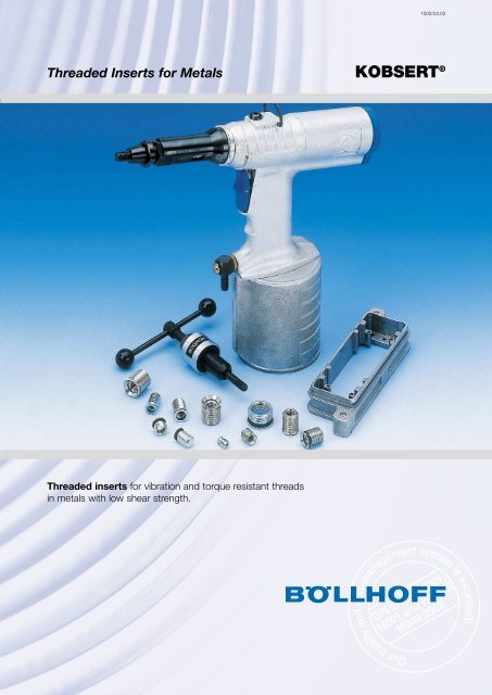
<strong>Threaded</strong> Inserts <strong>for</strong> Metals<br />
KOBSERT ®<br />
<strong>Threaded</strong> inserts <strong>for</strong> vibration and torque resistant threads<br />
in <strong>metals</strong> with low shear strength.
KOBSERT ® <strong>Threaded</strong> Inserts <strong>for</strong> Metals<br />
The Advantages:<br />
KOBSERT ® threaded inserts are one-piece fasteners <strong>for</strong> locking, vibration and torque resistant threads with high<br />
strength, <strong>for</strong> <strong>metals</strong> with low shear strength, like:<br />
Aluminium and aluminium alloys,<br />
Magnesium alloys.<br />
The KOBSERT ® is mechanically fixed in place without additional locking pins, adhesive or other additional<br />
elements.<br />
With KOBSERT ® threaded inserts, damaged threads can be repaired.<br />
The KOBSERT ® with sealing ring is designed <strong>for</strong> gas and liquid leakproofed joints.<br />
When installing the threaded inserts, the safety flange is pressed into the surface of the parent material.<br />
(This reduces the pipe-shaped neck area under the safety flange and covers as far as the mounting thread).<br />
After installation into the part, the threaded inserts are reliably protected against unscrewing, even when the part<br />
is exposed to dynamic screwload or extreme temperatures. Due to the installation process where the KOBSERT ®<br />
body is pulled into the same direction like the screwload, the clearance of the external thread is compensated.<br />
The external thread is pre setted proberly.<br />
If, in exceptional cases, it is necessary to remove the threaded insert, follow the instructions on page 8.<br />
Safety Flange<br />
KOBSERT ®<br />
<strong>Threaded</strong> Sockets<br />
Sealing Ring<br />
Compression Zone<br />
Component<br />
External Thread d 2<br />
Internal Thread d 1<br />
Design<br />
Metric ISO thread DIN 13, tolerance range <strong>for</strong> industry standard screws and nuts tolerance 6g/6H.<br />
Surface: – DIN 267 Part 2 Product Class A.<br />
Material: – Steel, galvanic Zink plated, colourless chromated (<strong>for</strong> order no. see page 3 – 7).<br />
– Stainless steel, coatless (5th digit of Order no. changes from 0 to 6).<br />
Sealing Ring /<br />
gasket:<br />
– PERBUNAN ® (eWZ Bayer AG) 70 Shore A, heat resistant to ~140 °C.<br />
– [VITON ® , eWZ E.I. Dupont de Nemours & Co. INC.], to 300 °C (put 1 as the 5th digit of the<br />
Order no.).<br />
Example Order: KOBSERT ® <strong>Threaded</strong> insert type 1030 M 10 x 18 Order no. 1030 010 0018<br />
i. e. Stated diameters M 10 = Internal Thread,<br />
Stated length = 18 mm = Length of threaded socket after installation is completed.<br />
Other specifications available on request.<br />
2
KOBSERT ® <strong>Threaded</strong> Inserts<br />
Type 1030<br />
L 1 (L 2 )<br />
d 3<br />
L 3<br />
Safety flange<br />
open version / through hole<br />
Material: Steel ➀ ,<br />
galvanic Zink plated,<br />
colourless chromated,<br />
other surface on demand<br />
d 1<br />
d 2<br />
D R<br />
Countersinking cylindrical portion<br />
is only necessary <strong>for</strong> aluminium<br />
alloys with high tensile strength<br />
(see page 4).<br />
d 2<br />
Installation tools, see pages 10 + 11<br />
d 1 Order no. d 2 d 3 L 1 * L 2 * L 3 * D R<br />
Knurl<br />
DIN 82<br />
M 6 1030 006 0010 M 10 6.8 10 11 2.7 11 1.2<br />
M 6 1030 006 0012 M 10 6.8 12 13 2.7 11 1.2<br />
M 8 1030 008 0015 M 12 x 1.5** 8.5 15 16 3.3 13 1.6<br />
M 10 1030 010 0018 M 14 x 1.5 10.5 18 19 3.3 15 1.6<br />
M 12 x 1.5 1030 012 4021 M 16 x 1.5 12.5 21 22 3.5 17 1.6<br />
M 12 1030 012 0021 M 16 x 1.5 12.5 21 22 3.5 17 1.6<br />
M 14 x 1.5 1030 014 4024 M 20 x 1.5 15.5 24 25 3.6 21 1.6<br />
M 14 1030 014 0024 M 20 x 1.5 15.5 24 25 3.6 21 1.6<br />
M 16 x 1.5 1030 016 4026 M 22 x 1.5 17.5 26 27 3.6 23 1.6<br />
M 16 1030 016 0026 M 22 x 1.5 17.5 26 27 3.6 23 1.6<br />
* L 1 /L 3 = Lengths in assembled condition. * L 2 = Lengths in delivery condition. Other lengths available on request.<br />
** also available <strong>for</strong> delivery with 1.25 thread<br />
➀ Other materials on request, <strong>for</strong> technical specifications see page 2.<br />
Subject to technical alterations.<br />
3
t<br />
KOBSERT ® <strong>Threaded</strong> Inserts<br />
Type 1031<br />
L 1 (L 2 )<br />
d 3 d 4<br />
d 1<br />
d 1 *<br />
d 2<br />
L 3<br />
120°<br />
d 5<br />
Safety flange<br />
open version /<br />
through hole<br />
With sealing ring:<br />
PERBUNAN ®<br />
Material: Steel ➀ ,<br />
galvanic Zink plated,<br />
colourless chromated,<br />
other surface on<br />
demand<br />
d 6<br />
D R<br />
Sealing ring:<br />
PERBUNAN ® as standard, 70 Sh A,<br />
Heat resistance up to + 140 °C.<br />
Colour coding: black.<br />
d 2<br />
Countersinking cylindrical<br />
portion is only necessary<br />
<strong>for</strong> aluminium alloys with<br />
high tensile strength.<br />
Alternative: VITON ® 75 Sh A,<br />
Heat resistance up to + 300 °C.<br />
Colour coding: green.<br />
Installation tools, see pages 10 + 11<br />
d 1 Order no. d 2 d 3 L 1 * L 2 * L 3 * D R<br />
Knurl Sealing ring Countersink<br />
DIN 82 d 4 x d 5 d 6 Tol. t + Tol.<br />
M 10 x 1 ➁ 1031 010 3010 M 14 x 1.5 10.5 10 11 3.2 15 1.6 10 x 1.5 14 ± 0.10 2.5 0.3<br />
M 12 x 1.5 1031 012 4012 M 16 x 1.5 12.5 12 13 3.5 17 1.6 12 x 1.5 16 ± 0.10 2.5 0.3<br />
M 14 x 1.5 1031 014 4012 M 20 x 1.5 15.5 12 13 3.6 21 1.6 14 x 2.0 20 + 0.15/– 0.10 3.0 0.3<br />
M 16 x 1.5 1031 016 4012 M 22 x 1.5 17.5 12 13 3.6 23 1.6 16 x 2.0 22 + 0.15/– 0.10 3.0 0.3<br />
M 18 x 1.5 1031 018 4012 M 24 x 1.5 19.5 12 13 3.6 25 1.6 18 x 2.0 24 + 0.15/– 0.10 3.0 0.3<br />
M 20 x 1.5 1031 020 4014 M 26 x 1.5 21.5 14 15 3.6 27 1.6 20 x 2.0 26 + 0.15/– 0.10 3.0 0.3<br />
M 22 x 1.5 1031 022 4014 M 28 x 1.5 23.5 14 15 3.6 29 1.6 22 x 2.0 28 + 0.15/– 0.10 3.0 0.3<br />
M 24 x 1.5 1031 024 4014 M 30 x 1.5 25.5 14 15 3.6 31 1.6 24 x 2.0 30 + 0.15/– 0.10 3.0 0.3<br />
M 26 x 1.5 1031 026 4016 M 32 x 1.5 27.5 16 17 3.6 33 1.6 26 x 2.0 32 + 0.15/– 0.10 3.0 0.3<br />
* L 1 /L 3 = Length when assembled. * L 2 = lengths in delivery condition. Other lengths available on request.<br />
4<br />
➀ Other materials on request, <strong>for</strong> technical specifications see page 2.<br />
➁ Type 1031 is preferable <strong>for</strong> short screw lengths DIN 908 and 910.<br />
Subject to technical alterations.
t<br />
KOBSERT ® <strong>Threaded</strong> Inserts<br />
Type 1032<br />
L 1 (L 2 )<br />
d 3<br />
D<br />
L 3<br />
d 4<br />
d d 1<br />
1<br />
d 2<br />
120°<br />
d 5<br />
Safety flange with<br />
sealing flange<br />
open version /<br />
through hole<br />
With sealing ring:<br />
PERBUNAN ®<br />
Material: Steel ➀ ,<br />
galvanic Zink plated,<br />
colourless chromated,<br />
other surface on<br />
demand<br />
d 6<br />
Sealing ring:<br />
PERBUNAN ® as standard, 70 Sh A,<br />
Heat resistance up to + 140 °C.<br />
Colour coding: black.<br />
d 2<br />
Countersinking cylindrical<br />
portion is only necessary<br />
<strong>for</strong> aluminium alloys with<br />
high tensile strength.<br />
Alternative: VITON ® 75 Sh A,<br />
Heat resistance up to + 300 °C.<br />
Colour coding: green.<br />
Installation tools, see pages 10 + 11<br />
d 1 Order no. d 2 d 3 D L 1 * L 2 * L 3 * L 5 D R<br />
Knurl Sealing ring Countersink<br />
DIN 82 d 4 x d 5 d 6 Tol. t + Tol.<br />
M 10 x 1 1032 010 3011 M 14 x 1.5 10.5 16 11.0 12.0 4.0 0.8 15 1.6 10 x 1.5 14 ± 0.10 2.5 0.3<br />
M 12 x 1.5 1032 012 4145 M 16 x 1.5 12.5 18 14.5 15.5 4.4 0.8 17 1.6 12 x 1.5 16 ± 0.10 2.5 0.3<br />
M 14 x 1.5 1032 014 4145 M 20 x 1.5 15.5 22 14.5 15.5 4.5 1.0 21 1.6 14 x 2.0 20 + 0.15/– 0.10 3.0 0.3<br />
M 16 x 1.5 1032 016 4145 M 22 x 1.5 17.5 24 14.5 15.5 4.5 1.0 23 1.6 16 x 2.0 22 + 0.15/– 0.10 3.0 0.3<br />
M 18 x 1.5 1032 018 4145 M 24 x 1.5 19.5 26 14.5 15.5 4.7 1.2 25 1.6 18 x 2.0 24 + 0.15/– 0.10 3.0 0.3<br />
M 20 x 1.5 1032 020 4155 M 26 x 1.5 21.5 28 15.5 16.5 4.7 1.2 27 1.6 20 x 2.0 26 + 0.15/– 0.10 3.0 0.3<br />
M 22 x 1.5 1032 022 4155 M 28 x 1.5 23.5 30 15.5 16.5 4.7 1.2 29 1.6 22 x 2.0 28 + 0.15/– 0.10 3.0 0.3<br />
M 24 x 1.5 1032 024 4155 M 30 x 1.5 25.5 32 15.5 16.5 4.7 1.2 31 1.6 24 x 2.0 30 + 0.15/– 0.10 3.0 0.3<br />
M 26 x 1.5 1032 026 4175 M 32 x 1.5 27.5 34 17.5 18.5 4.7 1.2 33 1.6 26 x 2.0 32 + 0.15/– 0.10 3.0 0.3<br />
M 30 x 1.5 1032 030 4175 M 36 x 1.5 31.5 38 17.5 18.5 4.7 1.2 37 1.6 30 x 2.0 36 + 0.15/– 0.10 3.0 0.3<br />
* L 1 /L 3 = Lengths when assembled. * L 2 = Lengths in delivery condition. Other lengths available on request.<br />
➀ Other materials on request, <strong>for</strong> technical specifications see page 2.<br />
Subject to technical alterations.<br />
5
t<br />
KOBSERT ® <strong>Threaded</strong> Inserts<br />
Type 1033<br />
L 1 (L 2 )<br />
d 3<br />
d 1<br />
L 3<br />
L 4<br />
d 4<br />
d 1<br />
d 2<br />
120°<br />
d 6<br />
D R<br />
Sealing ring:<br />
PERBUNAN ® as standard, 70 Sh A,<br />
Heat resistance up to + 140 °C.<br />
Colour coding: black.<br />
d 2<br />
d 5<br />
Safety flange<br />
closed version /<br />
blind hole<br />
With sealing ring:<br />
PERBUNAN ®<br />
Material: Steel ➀ ,<br />
galvanic Zink plated,<br />
colourless chromated,<br />
other surface on<br />
demand<br />
Countersinking cylindrical<br />
portion is only necessary<br />
<strong>for</strong> aluminium alloys with<br />
high tensile strength.<br />
Alternative: VITON ® 75 Sh A,<br />
Heat resistance up to + 300 °C.<br />
Colour coding: green.<br />
Installation tools, see pages 10 + 11<br />
d 1 * Order no. d 2 d 3 L 1 ** L 2 ** L 3 ** L 4 ** D R Knurl Sealing ring Countersink<br />
DIN 82 d 4 x d 5 d 6 Tol. t + Tol.<br />
M 5 1033 005 0012 M 8 5.4 12 13 2.7 8.2 9 1.2 5 x 1.0 8 ± 0.10 2.0 0.3<br />
M 6 1033 006 0015 M 10 6.8 15 16 2.7 10.5 11 1.2 6 x 1.5 10 ± 0.10 2.5 0.3<br />
M 8 1033 008 0018 M 12 x 1.5 8.5 18 19 3.3 12.0 13 1.6 8 x 1.5 12 ± 0.10 2.5 0.3<br />
M 10 1033 010 0021 M 14 x 1.5 10.5 21 22 3.3 14.0 15 1.6 10 x 1.5 14 ± 0.10 2.5 0.3<br />
M 12 1033 012 0024 M 16 x 1.5 12.5 24 25 3.5 16.0 17 1.6 12 x 1.5 16 ± 0.10 2.5 0.3<br />
M 14 1033 014 0026 M 20 x 1.5 15.5 26 27 3.6 17.0 21 1.6 14 x 2.0 20 + 0.15/– 0.10 3.0 0.3<br />
M 16 1033 016 0031 M 22 x 1.5 17.5 31 32 3.6 21.0 23 1.6 16 x 2.0 22 + 0.15/– 0.10 3.0 0.3<br />
** Available with fine thread.<br />
** L 1 /L 3 /L 4 = Lengths in assembled condition. ** L 2 = Lengths in delivery condition. Other lengths on request.<br />
➀ Other materials on request, <strong>for</strong> technical specifications see page 2.<br />
Subject to technical alterations.<br />
6
t<br />
KOBSERT ® <strong>Threaded</strong> Inserts<br />
Type 1040<br />
Type 1041, with sealing ring*<br />
d 3<br />
d 1<br />
L 1 (L 2 )<br />
L 3<br />
d 4<br />
d 1<br />
d 5<br />
HP – High Power<br />
Safety flange<br />
open version /<br />
through hole<br />
With or without<br />
sealing ring<br />
Material: Steel ➀ ,<br />
galvanic Zink plated,<br />
colourless chromated<br />
d 2<br />
90°<br />
d 6<br />
D R<br />
d 2<br />
Sealing ring:<br />
PERBUNAN ® as standard, 70 Sh A,<br />
Heat resistance up to + 140 °C.<br />
Colour coding: black.<br />
Countersinking cylindrical<br />
portion is only necessary<br />
<strong>for</strong> aluminium alloys with<br />
high tensile strength.<br />
Alternative: VITON ® 75 Sh A,<br />
Heat resistance up to + 300 °C.<br />
Colour coding: green.<br />
Installation tools, see pages 10 + 11<br />
d 1 * Order no. d 2 d 3 L 1 ** L 2 ** L 3 ** D R<br />
Knurl Sealing ring Countersink<br />
DIN 82 d 4 x d 5 d 6 Tol. t + Tol.<br />
M 5 1040 005 0010 M 10 5.5 10 11.0 1.5 11 1.2 7 x 1.5 10 ± 0.1 2.5 0.3<br />
M 6 1040 006 0012 M 12 x 1.5 6.5 12 13.5 1.6 13 1.2 8 x 2.0 12 ± 0.1 3.0 0.3<br />
M 8 1040 008 0015 M 14 x 1.5 8.5 15 16.5 1.8 15 1.6 10 x 2.0 14 ± 0.1 3.5 0.3<br />
M 10 1040 010 0018 M 16 x 1.5 10.5 18 20.0 2.0 17 1.6 12 x 2.0 16 ± 0.1 4.0 0.3<br />
M 12 1040 012 0021 M 20 x 1.5 13.0 21 23.0 2.5 21 1.6 15 x 2.5 20 + 0.15/– 0.10 4.5 0.4<br />
M 14 1040 014 0024 M 22 x 1.5 15.0 24 26.0 2.5 23 1.6 17 x 2.5 22 + 0.15/– 0.10 4.5 0.4<br />
M 16 1040 016 0026 M 24 x 2.0 17.0 26 28.0 3.0 25 1.6 19 x 2.5 24 + 0.18/– 0.10 4.5 0.4<br />
M 20 1040 020 0030 M 30 x 2.0 21.0 30 32 3.5 31 1.6 23 x 3.5 30 + 0.18/– 0.10 4.5 0.4<br />
M 22 1040 022 0032 M 33 x 2.0 23.0 32 34 3.5 34 1.6 25 x 4.0 33 + 0.18/– 0.10 4.5 0.4<br />
M 24 1040 024 0034 M 36 x 3.0 25.0 34 36 3.5 37 1.6 27 x 4.5 36 + 0.18/– 0.10 4.5 0.4<br />
* Other diameters and threads on request.<br />
When ordering type 1041 (with sealing ring) the 4th digit of the order no. changes from 0 to 1.<br />
** L 1 /L 3 = Lengths when assembled.<br />
** L 2 = Lengths in delivery condition, other lengths available on request.<br />
➀ Other materials on request, <strong>for</strong> technical specifications see page 2.<br />
Subject to technical alterations.<br />
7
KOBSERT ® Installation Guidelines<br />
Mounting Thread<br />
Metric ISO threads according to DIN 13, tolerance 6 H.<br />
The mounting thread should checked with a thread gauge tolerance 6 H.<br />
Thread hole<br />
The minor diameter of the thread hole has to be drilled according to DIN 13 tolerance 6 H.<br />
In general, the tapped hole should not be countersunk. Chamfering is permissible, within the diameter,<br />
but should not be greater than the specified diameter of the mounting thread.<br />
If the KOBSERT ® or the KOBSERT ® HP is used with a sealing ring , a cylindrical partion in accordance with<br />
pages 3 to 7 should be created.<br />
Installation<br />
Manual and motor-driven tools are available <strong>for</strong> installing the KOBSERT ® . The KOBSERT ® insert is screwed into<br />
the part until the safety flange is in contact to the surface of the part. The installation procedure – pressing the<br />
safety flange into the part – is carried out by a relative axial movement between the spindle, which has been<br />
screwed in, and the frontend assembly of the installation tool. After the setting process the spindle has tube<br />
turned out of the KOBSERT ® .<br />
d 1<br />
L 1<br />
L<br />
Disassembly<br />
If KOBSERT ® threaded inserts must be removed from a part, it must be done as follows<br />
(see scetch):<br />
Drilling into the safety flange until reaching the external thread (Drill Ø = external thread Ø d 2 ).<br />
Lever out the safety flange using a scraper or a screwdriver.<br />
Insert a tool <strong>for</strong> unscrewing – if necessary a suitable scraper – into the internal thread,<br />
so it is possible to turn it. Unscrew the socket anticlockwise.<br />
New installation<br />
Screw in a threaded insert of the same specified size, until the safety flange is level with the previous impression –<br />
if necessary, unscrew it a little – and as usual, set it on one level with the surface using an KOBSERT ® installation<br />
tool.<br />
8
KOBSERT ® Installation Guidelines<br />
Wall thickness Specifications <strong>for</strong> Aluminium Materials (casted and <strong>for</strong>ging<br />
alloys)<br />
The minimum width S or the wall thickness S R depends on the tenside strength and the E-Modul of the parent<br />
material. The following <strong>for</strong>mula only gives guide values <strong>for</strong> aluminium alloys. For other materials, e. g. copper or<br />
brittle materials, the required wall thickness should be established by per<strong>for</strong>ming tests.<br />
Dimensions of the mounting thread see page 3 to 7.<br />
S<br />
S R<br />
S = 1.4 x D R<br />
S R = 0.2 x D R<br />
S —2<br />
D R<br />
D R<br />
S = Minimum width of workpiece<br />
S R = Minimum wall thickness<br />
D R = Outer diameter of safety flange<br />
(Knurl diameter)<br />
S<br />
— 2<br />
S R<br />
S<br />
Pressure and work areas at the various Installation Tools<br />
(see pages 10/11)<br />
Pneu.<br />
pressure<br />
Hydr.<br />
pressure<br />
400<br />
8<br />
350<br />
bar<br />
bar<br />
7 300<br />
6<br />
250<br />
5<br />
200<br />
4<br />
150<br />
3<br />
P 2001 K<br />
M 1430 EK/P 1430 EK<br />
M 1430 K<br />
2<br />
100<br />
50 Traction on threaded bolt [kN]<br />
0 10 20 30 40 50 60 70 80<br />
10.9 i<br />
M 5 M 6 M 8<br />
M 10 M 12<br />
yStrength class<br />
12.9t<br />
M 5 M 6<br />
M 8<br />
M 10<br />
Yield point of screw [100 %]<br />
Pull out load in relation to screw class on tensile strength of parent<br />
material<br />
M 24<br />
M 22<br />
M 20<br />
M 18<br />
M 16<br />
M 14<br />
M 12<br />
F 18<br />
F 22<br />
F 28<br />
F 32<br />
Pull out load <strong>for</strong> type 1030 and<br />
1033 KOBSERT ® threaded<br />
inserts in standard lengths, in<br />
different material qualities,<br />
including: F 18<br />
F 22<br />
F 26<br />
F 32<br />
Tear strengths are 30 to 50 % higher.<br />
Test strengths type<br />
1040/1041 on request.<br />
M 10<br />
M 8<br />
M 6<br />
M 5<br />
8.8<br />
12.9<br />
10.9<br />
Test strengths of screws of<br />
different strength classes<br />
(8.8 – 10.9 –12.9) ~ 90% of screw<br />
yield point.<br />
10 3 2 3 4 5 6 7 8 9 10 4<br />
2 3<br />
4<br />
da N<br />
Average installation strength <strong>for</strong><br />
KOBSERT ® threaded inserts.<br />
9
Tools <strong>for</strong> KOBSERT ® <strong>Threaded</strong> Inserts<br />
Manual Installation Tools Type S 5 to S 12<br />
Screw Tool <strong>for</strong> Individual Assembly<br />
Description<br />
B 73 000<br />
Type<br />
Included in delivery<br />
Complete tool<br />
Spares<br />
<strong>Threaded</strong> bolt<br />
Spindle nut<br />
Specified<br />
Ø Order no. Order no. Order no.<br />
S 5 M 5 2353 010 5000 2353 010 5020 2353 010 0050<br />
S 6 M 6 2353 010 6000 2353 010 6020 2353 010 0050<br />
S 8 M 8 2353 010 8000 2353 010 8020 2353 010 0050<br />
S 10<br />
The tools<br />
S 5 to S 12 x 1.5<br />
are only available<br />
as a set. M 10 2353 011 0000 2353 011 0020 2353 010 0051<br />
S 10 x 1 M 10 x 1 2353 011 0300 2353 011 0320 2353 010 0351<br />
S 12 M 12 2353 011 2000 2353 011 2020 2353 010 0051<br />
S 12 x 1.5 M 12 x 1.5 2353 011 2400 2353 011 2420 2353 010 0451<br />
Manual Installation Tool Type M 1430 K<br />
Hydraulic Manual Tool <strong>for</strong> small series, use as an Installation Tool with the AL 250 power unit<br />
Description<br />
B 73 000<br />
Type<br />
Tools<br />
Replacement part<br />
without threaded bolt with threaded bolt threaded bold<br />
Specified and adaptor<br />
and adaptor<br />
Order no. Ø Order no. Order no.<br />
M 14 1069 011 4000 1069 011 4020<br />
M 14 x 1.5 1069 011 4400 1069 011 4420<br />
M 16 1069 011 6000 1069 011 6020<br />
M 16 x 1.5 1069 011 6400 1069 011 6420<br />
M 18 x 1.5 1069 011 8400* 1069 011 8420*<br />
M 1430-K 1069 020 0000 M 20 x 1.5 1069 012 0400* 1069 012 0420*<br />
M 22 x 1.5 1069 012 2400* 1069 012 2420*<br />
M 24 x 1.5 1069 012 4400* 1069 012 4420*<br />
M 26 x 1.5 1069 012 6400* 1069 012 6420*<br />
M 28 x 1.5 1069 012 8400* 1069 012 8420*<br />
M 30 x 1.5 1069 013 0400* 1069 013 0420*<br />
** <strong>Threaded</strong> bolt is in two<br />
parts from M 16<br />
AL 250 Power Unit<br />
Hydraulic Hand Pump <strong>for</strong> Small Series<br />
AL 250<br />
with<br />
manometer<br />
1069 080 0000<br />
Machine Installation Tool Type P 2001 K<br />
Hydraulic-Pneumatic Tool <strong>for</strong> Assembling the Business Series<br />
Description<br />
Type<br />
Tools Interchangeable unit Spares<br />
without with threaded (only threaded bolt<br />
threaded bolt bolt and and chuck) <strong>Threaded</strong> bolt Chuck<br />
and chuck Specified chuck<br />
Order no. Ø Order no. Order no. Order no. Order no.<br />
M 5 1061 530 5000 1061 530 5010 2361 130 5020 1061 530 5030<br />
M 6 1061 530 6000 1061 530 6010 2361 130 6020 1061 530 6030<br />
P 2001 K 1061 530 0000 M 8 1061 530 8000 1061 530 8010 2361 130 8020 1061 530 8030<br />
M 10 1061 531 0000 1061 531 0010 2361 131 0020 1061 531 0030<br />
M 10 x 1 1061 531 0300 1061 531 0310 2361 131 0320 1061 531 0330<br />
Special tools on request.<br />
10
Tools <strong>for</strong> KOBSERT ® <strong>Threaded</strong> Inserts<br />
Machine Installation Tools Type M 830 K<br />
Hydraulic Installation Tool with Manual Transmission <strong>for</strong> Middle Series<br />
Description<br />
Type<br />
Tools Replacement unit Spares<br />
without threaded with threaded (only threaded bolt<br />
bolt and chuck<br />
Specified<br />
bolt and chuck and chuck) <strong>Threaded</strong> bolt Chuck<br />
Order no. Ø Order no. Order no. Order no. Order no.<br />
M 8* 1061 060 8000 1061 070 8010 1061 070 8020 1061 070 8030<br />
M10* 1061 061 0000 1061 071 0010 1061 071 0020 1061 071 0030<br />
M10x1* 1061 061 0300 1061 071 0310 1061 071 0320 1061 071 0330<br />
M12* 1061 061 2000 1061 071 2010 1061 071 2020 1061 071 2030<br />
M12x1.5* 1061 061 2400 1061 071 2410 1061 071 2420 1061 071 2430<br />
M 14 1061 061 4000 1061 071 4010 1061 071 4020 1061 071 4030<br />
M 14 x1.5 1061 061 4400 1061 071 4410 1061 071 4420 1061 071 4430<br />
M 1430-EK 1061 060 0000 M 16 1061 061 6000 1061 071 6010 1061 071 6020 1061 071 6030<br />
M 16 x1.5 1061 061 6400 1061 071 6410 1061 071 6420 1061 071 6430<br />
M 18 x1.5 1061 061 8400 1061 071 8410 1061 071 8420 1061 071 8430<br />
M 20 x1.5 1061 062 0400 1061 072 0410 1061 072 0420 1061 072 0430<br />
M 22 x1.5 1061 062 2400 1061 072 2410 1061 072 2420 1061 072 2430<br />
M 24 x1.5 1061 062 4400 1061 072 4410 1061 072 4420 1061 072 4430<br />
M 26 x1.5 1061 062 6400 1061 072 6410 1061 072 6420 1061 072 6430<br />
M 28 x1.5 1061 062 8400 1061 072 8410 1061 072 8420 1061 072 8430<br />
M 30 x1.5 1061 063 0400 1061 073 0410 1061 073 0420 1061 073 0430<br />
Machine Installation Tool Type P 830 K<br />
Hydraulic Installation Tool with Pneumatic Transmission <strong>for</strong> Larger Series<br />
M 8* 1061 070 8000 1061 070 8010 1061 070 8020 1061 070 8030<br />
M10* 1061 071 0000 1061 071 0010 1061 071 0020 1061 071 0030<br />
M10x1* 1061 071 0300 1061 071 0310 1061 071 0320 1061 071 0330<br />
M12* 1061 071 2000 1061 071 2010 1061 071 2020 1061 071 2030<br />
M12x1.5* 1061 071 2400 1061 071 2410 1061 071 2420 1061 071 2430<br />
M 14 1061 071 4000 1061 071 4010 1061 071 4020 1061 071 4030<br />
M 14 x1.5 1061 071 4400 1061 071 4410 1061 071 4420 1061 071 4430<br />
P 1430-EK 1061 070 0000 M 16 1061 071 6000 1061 071 6010 1061 071 6020 1061 071 6030<br />
M 16 x1.5 1061 071 6400 1061 071 6410 1061 071 6420 1061 071 6430<br />
M 18 x1.5 1061 071 8400 1061 071 8410 1061 071 8420 1061 071 8430<br />
M 20 x1.5 1061 072 0400 1061 072 0410 1061 072 0420 1061 072 0430<br />
M 22 x1.5 1061 072 2400 1061 072 2410 1061 072 2420 1061 072 2430<br />
M 24 x1.5 1061 072 4400 1061 072 4410 1061 072 4420 1061 072 4430<br />
M 26 x1.5 1061 072 6400 1061 072 6410 1061 072 6420 1061 072 6430<br />
M 28 x1.5 1061 072 8400 1061 072 8410 1061 072 8420 1061 072 8430<br />
M 30 x1.5 1061 073 0400 1061 073 0410 1061 073 0420 1061 073 0430<br />
Power unit E 250 Electric Hydropump, including electric foot-switch <strong>for</strong> all hydraulically driven<br />
Installation Tools. Pressures from 100 to 300 bars can be used.<br />
Stationary installation machines on request.<br />
E 250 2365 010 0000<br />
* When ordering with these measurements the material<br />
receiving the inserts and the installation pressure must be<br />
checked. You should carry out a practice assembly<br />
Tools <strong>for</strong> rent on request.<br />
We reserve the right to make technical modifications.<br />
11
Böllhoff International<br />
North Europe<br />
Wilhelm Böllhoff GmbH & Co. KG, Bielefeld<br />
Böllhoff GmbH, Bielefeld with branches<br />
in Bielefeld, Braunschweig, Burgau, Dormagen,<br />
Leipzig, Munich, Nuremberg and Stuttgart,<br />
Böllhoff Verbindungstechnik GmbH, Bielefeld<br />
Böllhoff Systemtechnik GmbH & Co. KG, Bielefeld,<br />
Böllhoff Schraubtechnik GmbH, Bielefeld<br />
Böllhoff Produktion GmbH & Co. KG, Bielefeld and Sonnewalde,<br />
Germany<br />
Bollhoff Fastenings Ltd., Birmingham, Great Britain<br />
South-West Europe<br />
Bollhoff Otalu s. a., La Ravoire,<br />
Bollhoff Usinec s. a., Paris,<br />
France<br />
Bollhoff S.P.R.L., Aalst, Belgium<br />
Bollhoff s.r.l., Mailand, Italy<br />
Bollhoff s.a., Madrid, Spain<br />
South-East Europe<br />
Böllhoff GmbH, Linz, Austria<br />
Böllhoff Kft, Székesfehérvár, Hungary<br />
Böllhoff s. r. o., Prag, Czech-Republic<br />
Böllhoff s.r.l., Bors, Romania<br />
Bimex-Böllhoff*, Lańcut and Lipno, Poland<br />
Böllhoff-Master*, Russia<br />
North America<br />
Bollhoff RIVNUT ® Inc., Kendallville, Indiana, USA<br />
Bollhoff S.A. de C.V., Mexico City, Mexico<br />
South America<br />
Bollhoff Adm. e Part. Ltda., Jundiaí,<br />
Bollhoff Service Center Ltda., São Paulo, Porto Allegre and Curitiba<br />
Arquimedes Participacoes S.A, Jundiaí,<br />
MollerTech Bollhoff Ltda.*, Jundiaí and Curitiba,<br />
Bollhoff Neumayer Industrial Ltda.*, Jundiaí,<br />
Brazil<br />
Bollhoff S.A., Buenos Aires, Argentinia<br />
South-East Asia<br />
Böllhoff Trading Company, Shanghai, China (VR)<br />
*Joint-Ventures<br />
In addition to Böllhoff companies in these 17 countries, the company has a network of<br />
agents and dealers serving an international customer base on major industrial markets<br />
world-wide.<br />
Böllhoff Verbindungstechnik GmbH · Archimedesstraße 1– 4 · 33649 Bielefeld · Germany<br />
Phone +49 (0)5 21 / 44 82-03 (2 32) · Fax - 3 71 · Internet www.boellhoff.com · E-Mail mkethur@boellhoff.com