The Allrounder for complex grinding jobs. - Fritz Studer AG
The Allrounder for complex grinding jobs. - Fritz Studer AG
The Allrounder for complex grinding jobs. - Fritz Studer AG

You also want an ePaper? Increase the reach of your titles
YUMPU automatically turns print PDFs into web optimized ePapers that Google loves.
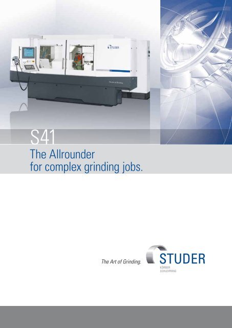
S41<br />
<strong>The</strong> <strong>Allrounder</strong><br />
<strong>for</strong> <strong>complex</strong> <strong>grinding</strong> <strong>jobs</strong>.
Advantages<br />
S41 – Dimensions<br />
• Distance between centers<br />
1 000 / 1 600 mm<br />
• Center height 225 / 275 mm<br />
• Maximum workpiece weight 250 kg<br />
Hardware<br />
• <strong>Studer</strong>Guide ® guide system with<br />
linear drive<br />
• Turret wheelhead with direct drive<br />
and 0.00005° resolution<br />
• Complete machining with up to four<br />
<strong>grinding</strong> wheels<br />
• C axis <strong>for</strong> the workhead enabling <strong>for</strong>m<br />
and thread <strong>grinding</strong><br />
• Full enclosure with two sliding doors<br />
• Granitan ® mineral-casting S103<br />
machine base<br />
Software<br />
• Very simple operation and programming<br />
thanks to <strong>Studer</strong>WIN<br />
• <strong>Studer</strong>GRIND programming software<br />
<strong>for</strong> the creation of <strong>grinding</strong> and dressing<br />
programs directly on the machine<br />
control, or on an external PC<br />
• Reduced setup and resetting times<br />
with <strong>Studer</strong> Quick-Set<br />
• Standardized interfaces <strong>for</strong> loader and<br />
peripheral devices<br />
S41<br />
2
Range of parts <strong>for</strong> external, internal and <strong>for</strong>m <strong>grinding</strong><br />
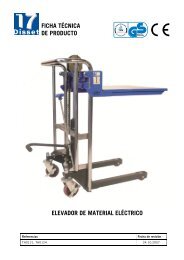
<strong>The</strong> <strong>Allrounder</strong><br />
<strong>for</strong> <strong>complex</strong> <strong>grinding</strong> <strong>jobs</strong>.<br />
<strong>The</strong> S41 is a CNC universal cylindrical <strong>grinding</strong><br />
machine of the latest generation. It boasts many<br />
technical features, such as the revolutionary<br />
<strong>Studer</strong>Guide ® guideway system, high-precision<br />
axis drives with linear motors, extremely fast<br />
direct drive of the B-axis, an even larger selection<br />
of wheelhead variants etc..<br />
<strong>The</strong> S41 meets every possible requirement.<br />
Thanks to the center height of 225 or 275 mm<br />
and a distance between centers of 1 000 or<br />
1 600 mm, the majority of daily <strong>grinding</strong> tasks<br />
can be efficiently per<strong>for</strong>med on this machine.<br />
Naturally the S41 can also be configured as<br />
a single-purpose machine <strong>for</strong> large batch<br />
production. <strong>The</strong> S41 can make full use of its<br />
speed particularly in applications where short<br />
auxiliary times are important.<br />
Precision is the result of perfect interaction<br />
between a large number of different factors.<br />
<strong>The</strong> base is the GRANITAN ® S103 machine bed<br />
with its excellent damping characteristics and<br />
favorable thermal behavior. <strong>The</strong> modules are<br />
ideally suited to each other and produced with<br />
customary <strong>Studer</strong> precision. <strong>The</strong> large distance<br />
between the guideways and the very rigidly<br />
constructed slides <strong>for</strong>m the basis <strong>for</strong> the precision<br />
and productivity of this machine. All components<br />
involved in defining precision are temperaturestabilized.<br />
<strong>Studer</strong>WIN as user interface and the software<br />
module by <strong>Studer</strong>GRIND create a stable programming<br />
environment and contribute to efficient use<br />
of the machine. A PC is integrated into the<br />
CNC control. <strong>The</strong> possibility of integrating the<br />
in-process gauging and sensor technology <strong>for</strong><br />
process monitoring as well as contact detection<br />
and automatic balancing systems in the control<br />
enable standardized programming of the different<br />
systems. <strong>The</strong> software <strong>for</strong> an internal loading<br />
system is also integrated in the control. <strong>The</strong><br />
driver elements are optimally adapted to the<br />
control.<br />
3
1<br />
Cast iron<br />
machine base<br />
Amplitude<br />
Granitan ®<br />
machine base<br />
- Vibration-damping<br />
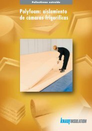
1 | Vibration behavior of gray cast iron and<br />
Granitan ® S103<br />
2 | Machine base with X amd Z guideways<br />
3 | Machine base with longitudinal and cross slides<br />
4 | X-axis with linear motor<br />
5 | Double T-slot and clamping surface <strong>for</strong> mounting<br />
dressing tool holders etc.<br />
6 | Setup scale<br />
Frequency<br />
- <strong>The</strong>rmally stable<br />
- Non-wearing<br />
Granitan ® S103 mineral casting machine bed<br />
<strong>The</strong> material structure-developed by <strong>Studer</strong> which<br />
has proved its superb efficiency over many years<br />
is produced in the company’s own plant using<br />
the most modern industrial techniques.<br />
• <strong>The</strong> excellent dampening behavior of the<br />
machine base ensures outstanding surface<br />
quality of the ground workpieces. <strong>The</strong> service<br />
life of the <strong>grinding</strong> wheel is also increased,<br />
leading to reduced downtimes.<br />
• Temporary temperature fluctuations are extensively<br />
compensated by the favorable<br />
thermal behavior of Granitan ® . This provides<br />
high stability throughout the day.<br />
• <strong>The</strong> <strong>Studer</strong>Guide ® guide system <strong>for</strong> the<br />
longitudinal and cross slides is moulded<br />
directly into the machine base and finished<br />
with a wear-resistant Granitan ® S200 surfacing<br />
material. <strong>The</strong> guideways offer the<br />
highest possible accuracy through the entire<br />
speed range with high load capacity and<br />
dampening levels. Thanks to the robust and<br />
maintenance-free design, these excellent<br />
guideway characteristics are more or less<br />
completely retained.<br />
2<br />
4
3<br />
4<br />
- High geometrical<br />
traverse precision<br />
- Setup scale <strong>for</strong> setup and<br />
resetting<br />
- Effective covering<br />
of guideways<br />
5<br />
<strong>Studer</strong>Guide ® in longitudinal and cross slides<br />
<strong>The</strong> longitudinal and cross slides are manufactured<br />
from high-quality gray cast iron and have<br />
highly precise, ground guideways.<br />
<strong>The</strong> slides rest completely on the guideways of<br />
the machine bed through the entire traversing<br />
range. This provides the cornerstone <strong>for</strong> the<br />
excellent straightness of 0.003 mm over 950 mm<br />
measured length.<br />
<strong>The</strong> top of the longitudinal slide has a surface<br />
that is ground over its entire length and acts<br />
as a support <strong>for</strong> the workhead, the tailstock,<br />
as well as accessories and devices. A setup<br />
scale, recessed in the table, makes it easy to<br />
set up and reset the units on the table. An<br />
additional T-slot with a ground surface enables<br />
the optimal utilization of dressing devices.<br />
structure. A huge advantage of <strong>Studer</strong>Guide ®<br />
over hydrostatic guideways is the damping<br />
component in the movement direction.<br />
<strong>The</strong> slides are powered by linear motors with<br />
direct measuring systems with a resolution<br />
of 10 nanometers. <strong>The</strong> maximum travel speed<br />
<strong>for</strong> both axes is 20 m / min. This lays the basis<br />
<strong>for</strong> high-precision and efficient <strong>grinding</strong> with<br />
the shortest possible auxiliary times.<br />
<strong>The</strong> combination of <strong>Studer</strong>Guide ® , linear motors<br />
and direct measuring systems guarantees the<br />
highest interpolation accuracies.<br />
6<br />
<strong>The</strong> newly developed <strong>Studer</strong>Guide ® guide<br />
system extends the advantages of hydrostatic<br />
systems and guideways with patented surface<br />
5
2<br />
3 4<br />
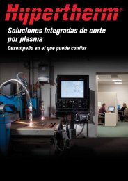
Turret wheelhead<br />
<strong>The</strong> most important component <strong>for</strong> complete<br />
machining is the wheelhead with integrated<br />
B-axis. It swivels automatically, and enables<br />
the use of up to four <strong>grinding</strong> wheels. This means<br />
that workpieces can be completely machined<br />
in the same clamping – with minimal auxiliary<br />
times combined with superior precision.<br />
This B axis has a direct drive, which positions<br />
very quickly and precisely. <strong>The</strong> high-resolution<br />
direct measuring system guarantees a positioning<br />
range of the high-precision B-axis < 0,1“.<br />
1<br />
1 / 2 | Turret wheelhead left / right / internal<br />
3 | HSG spindle<br />
4 | Positioning probe horizontal to the work plane<br />
6
Wheelhead variants<br />
Combinations of up to four external <strong>grinding</strong><br />
wheels or three internal <strong>grinding</strong> spindles result<br />
in more than 30 basic variants. Internal <strong>grinding</strong><br />
spindles with 6 000 rpm to 120 000 rpm can be<br />
used. Automatic balancing systems and frequency<br />
converters <strong>for</strong> the individual external <strong>grinding</strong><br />
spindles enable even better coordination of the<br />
wheelhead variants with the <strong>grinding</strong> process. A<br />
vertical spindle <strong>for</strong> <strong>grinding</strong> splines or a longitudinal<br />
<strong>grinding</strong> axis <strong>for</strong> non-interpolating traverse <strong>grinding</strong><br />
of internal tapers can also be mounted on the<br />
wheelhead as a special solution.<br />
- Configurable in accordance<br />
with customer’s requirements<br />
- Complete machining<br />
- Grinding of cylindrical and<br />
conical parts with the same<br />
<strong>grinding</strong> wheel<br />
Universal<br />
Tandem<br />
Diagonal<br />
Internal <strong>grinding</strong><br />
HSG possible<br />
HSG not possible<br />
7
Workhead<br />
<strong>The</strong> versatile universal workhead enables both<br />
live spindle <strong>grinding</strong> and <strong>grinding</strong> between<br />
centers. <strong>The</strong> machine can also be fitted with a<br />
specially designed chuck workhead <strong>for</strong> chuck<br />
applications. <strong>The</strong> workheads are mounted on<br />
roller bearings, are low-maintenance and possess<br />
an excellent roundness accuracy of below<br />
0.0004 mm (optionally 0.0002 mm) during live<br />
spindle <strong>grinding</strong> operations. <strong>The</strong> fine adjustment<br />
allows <strong>for</strong> cylindricity corrections in the 1 µm<br />
range during live spindle operations. Like the<br />
tailstock, the workhead is also equipped with an<br />
air cushion lift-off to simplify movement during<br />
setup and resetting.<br />
1<br />
- High roundness accuracy<br />
- Low-maintenance<br />
- Air cushion<br />
2<br />
3<br />
8
Direct-drive workhead<br />
<strong>The</strong> direct-drive workhead is primarily used <strong>for</strong><br />
live spindle <strong>grinding</strong> of heavy workpieces and<br />
<strong>for</strong> high-precision C-axis applications.<br />
With <strong>for</strong>m <strong>grinding</strong>, the spectrum of parts is<br />
expanded by the design configuration of the<br />
direct drive. <strong>The</strong> design also allows the installation<br />
of a high-precision measuring system directly<br />
on the spindle. This workhead does not have<br />
a fixed center.<br />
4<br />
C-axis <strong>for</strong> <strong>for</strong>m and thread <strong>grinding</strong><br />
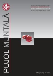
1 | Universal workhead<br />
2 | Roundness accuracy (test certificate)<br />
3 | Fine adjustment <strong>for</strong> cylindricity corrections<br />
4 | Direct-drive workhead<br />
5 | External and internal thread <strong>grinding</strong><br />
6 | Form and die <strong>grinding</strong><br />
7 | Contact ratios during <strong>for</strong>m <strong>grinding</strong><br />
Complete machining also entails <strong>for</strong>m and thread<br />
<strong>grinding</strong> operations to an ever increasing extent.<br />
<strong>The</strong>se processes are made possible by the<br />
position and speed-controlled C-axis. <strong>The</strong> standard<br />
C-axis with measuring system on the drive<br />
motor is suitable <strong>for</strong> thread <strong>grinding</strong>. A direct<br />
measuring system is mounted on the workhead<br />
spindle (C-axis) to ensure the highest <strong>for</strong>m<br />
accuracy). Acceleration and <strong>grinding</strong> <strong>for</strong>ces<br />
are absorbed without difficulty through the high<br />
dynamic rigidity of the axis drives.<br />
Form and thread <strong>grinding</strong><br />
<strong>The</strong> <strong>Studer</strong> S41 enables axis-parallel <strong>grinding</strong><br />
of conventional threads up to threads <strong>for</strong> high<br />
accuracy application. Polygons, excenters, control<br />
cams, cams etc. can be manufactured costeffectively<br />
and in the highest precision with<br />
High Speed Machining (HSM).<br />
5 6 7<br />
9
Tailstock<br />
<strong>The</strong> generously dimensioned barrel, designed<br />
<strong>for</strong> the deployment of Morse 4 taper centers,<br />
glides in the tailstock housing. <strong>The</strong> center pressure<br />
can be adjusted with the delicate precision<br />
required <strong>for</strong> <strong>grinding</strong> high-precision workpieces.<br />
<strong>The</strong> tailstock can be equipped with a hydraulically<br />
actuated barrel retraction <strong>for</strong> workpiece<br />
changeover. <strong>The</strong> fine adjustment enables cylindricity<br />
corrections in the range below 1 µm when<br />
<strong>grinding</strong> between centers. An air cushion liftoff<br />
facilitates simple movement during setup<br />
and resetting.<br />
<strong>The</strong> center pressure can be increased with<br />
the hydraulically operated tailstock, enabling a<br />
workpiece weight between centers of 250 kg.<br />
Synchronous tailstock<br />
Use of the synchronous tailstock is particularly<br />
cost-effective when manufacturing part families,<br />
when <strong>grinding</strong> a workpiece over its entire length<br />
or if the use of a conventional driver is not<br />
possible.<br />
A cooling lubricant is passed through the tailstock<br />
and totally covers the barrel and diamond<br />
holder, in order to guarantee optimum thermal<br />
stability. Clamping is per<strong>for</strong>med by a spring.<br />
This tailstock is suitable <strong>for</strong> workpiece weights<br />
up to 150 kg.<br />
2<br />
- Cylindricity corrections<br />
- <strong>The</strong>rmal stabilization<br />
by coolant flooding<br />
1<br />
3<br />
4<br />
10
1 | Tailstock<br />
2 | Hydraulic tailstock<br />
3 | Synchronous tailstock<br />
4 | Fine adjustment <strong>for</strong> cylindricity corrections<br />
5 | Swiveling dressing unit<br />
6 | Diamond holder behind tailstock on table<br />
7 | Dressing parameters dialog screen<br />
6<br />
Dressing<br />
7<br />
An easy-cutting <strong>grinding</strong> wheel is essential <strong>for</strong><br />
cost-effective and high-quality <strong>grinding</strong>. <strong>Studer</strong><br />
offers a large selection of dressing units, in order<br />
to coordinate the dressing process flexibly and<br />
optimally with the properties specific to the<br />
work-piece, tool or materials. <strong>The</strong> <strong>grinding</strong><br />
wheel profile and dressing parameters are<br />
easily defined via macros. Another <strong>Studer</strong><br />
speciality is the <strong>grinding</strong> wheel reference<br />
points (T-numbers). This enables programming<br />
with normal dimensions, which considerably<br />
simplifies the programming of <strong>grinding</strong> programs.<br />
A software package is available to fine tune<br />
the dressing process and includes additional<br />
dressing functions.<br />
5<br />
11
Control system and operation<br />
<strong>The</strong> S41 is equipped with a 31i-A series Fanuc<br />
control with integrated PC. <strong>The</strong> 15" touch screen<br />
facilitates intuitive operation and programming<br />
of the machine.<br />
<strong>The</strong> electrical cabinet is positioned behind the<br />
machine. <strong>The</strong> power and control compartments<br />
are spatially separated. <strong>The</strong> layout of the elements<br />
complies with the relevant safety norms and is<br />
EMC-tested.<br />
A special function – the Sensitron electronic<br />
contact detection device – reduces downtimes<br />
to a minimum.<br />
A free-standing height and tilt adjustable<br />
operating panel on casters is optionally available.<br />
All controls are clearly and ergonomically arranged.<br />
An important role is played by the manual control<br />
unit, which facilitates setup close to the <strong>grinding</strong><br />
process.<br />
2<br />
1<br />
3<br />
- PCU manual control unit<br />
- EMC-tested control cabinet<br />
- Ergonomically arranged<br />
controls<br />
12
1 | Machine control<br />
2 | Manual control unit<br />
3 | Optional control panel<br />
4 | <strong>Studer</strong>WIN<br />
5 | Workpiece programming<br />
6 | Assisted setup<br />
4<br />
- Latest software technology<br />
- Pictogramming<br />
<strong>Studer</strong>WIN<br />
<strong>The</strong> user interface <strong>Studer</strong>WIN creates a stable<br />
programming environment and contributes to<br />
efficient use of the machine. <strong>The</strong> possibility of<br />
fully integrating the in-process gauging and sensor<br />
technology <strong>for</strong> process control as well as contact<br />
detection and automatic balancing systems in<br />
the operator interface enables standardized<br />
programming of the different systems. <strong>The</strong><br />
software of an optional loading system is also<br />
integrated. <strong>The</strong> drive elements are optimally<br />
matched to the control system.<br />
<strong>The</strong> sophisticated mechanical engineering<br />
concept of the S41 is completed by a <strong>grinding</strong><br />
software program developed in-house by <strong>Studer</strong><br />
and which is continuously optimized in collaboration<br />
with users of the software. This software<br />
offers:<br />
• Pictogramming: <strong>The</strong> operator strings the individual<br />
<strong>grinding</strong> cycles together – the control<br />
generates the ISO code.<br />
• Quick-Set: <strong>The</strong> software <strong>for</strong> <strong>grinding</strong> wheel alignment<br />
reduces resetting times by up to 90 %.<br />
• Microfunctions: Free programming of <strong>grinding</strong><br />
and dressing process sequences <strong>for</strong> optimization<br />
of the <strong>grinding</strong> process.<br />
• Integrated operating instructions assist safe<br />
machine operation.<br />
• <strong>The</strong> software options <strong>for</strong> the <strong>grinding</strong> technology<br />
calculations, optimized dressing as well as<br />
the Contour-, Thread- and Form<strong>grinding</strong> cycles<br />
increase the functionality of the machine.<br />
5<br />
6<br />
13
Process-optimized complete solutions guarantee greater<br />
efficiency and reliability throughout.<br />
Loading systems are available <strong>for</strong> the <strong>Studer</strong><br />
S41, which can be precisely adapted to the<br />
machine application and the machining processes<br />
thanks to their modular design. <strong>The</strong> appropriate<br />
peripherals ensure seamless integration into<br />
the respective production process. <strong>The</strong> handling<br />
systems communicate with the machine via the<br />
standardized loader interface and enable even<br />
<strong>complex</strong> handling tasks to be solved. Comprehensive<br />
quality control is possible during the<br />
<strong>grinding</strong> process. This entails: in-process, postprocess,<br />
recording, evaluation and correction.<br />
This type of quality assurance is crucial during<br />
<strong>grinding</strong>, but especially during match <strong>grinding</strong>.<br />
1<br />
2 3<br />
- Automatic production -<br />
processes<br />
- Integrated quality control<br />
- Standard loader – interfaces<br />
14
4<br />
1 | Customized system machine<br />
2 | Working space with workpiece handling<br />
3 | Post-process station<br />
4 | Deployment of engineers on the customer’s<br />
premises<br />
5 | Training on the machine<br />
6 | Operating worldwide<br />
5<br />
Customer Service<br />
Machines must consistently fulfil customer<br />
requirements, operate cost-effectively and reliably,<br />
and be constantly available.<br />
30 competent HelpLines worldwide as well<br />
as spare parts staff and more than 60 service<br />
technicians in your area will be there <strong>for</strong> you<br />
throughout the lifetime of your <strong>Studer</strong> machine:<br />
• We will find a quick solution to your problems<br />
• We will provide assistance promptly and<br />
without fuss<br />
• We will help you to increase your<br />
productivity<br />
• We work professionally, reliably and<br />
transparently<br />
6<br />
Start up Know-how Service<br />
For a smooth production<br />
start.<br />
For trained, motivated<br />
personnel and increased<br />
productivity.<br />
For quick and professional<br />
problem solving.<br />
Prevention Material Renew<br />
For long-term precautions<br />
and detailed monitoring.<br />
For perfect fitting accuracy<br />
and process reliability<br />
with <strong>Studer</strong> original parts.<br />
To give your <strong>grinding</strong><br />
machine a new lease of life.<br />
15
Main dimensions<br />
Distance between centers 1 000 / 1 600 mm (39.4“/ 63“)<br />
Center height 225 / 275 mm (8.9“/ 10.8“)<br />
Max. workpiece weight between centers<br />
250 kg (550 lbs)<br />
Cross slide: X-axis<br />
Max. travel 350 mm (13.8“)<br />
Speed<br />
0.001 – 20 000 mm / min (0.000,04 – 787 ipm)<br />
Resolution 0.00001 mm (0.000,000,4“)<br />
Longitudinal slide: Z-axis<br />
Max. travel 1 150 / 1750 mm (45.3“/ 68.9“)<br />
Speed<br />
0.001 – 20 000 mm / min (0.000,04 – 787 ipm)<br />
Resolution 0.00001 mm (0.000,000,4“)<br />
Wheelhead<br />
Swiveling range<br />
-30 to +225 deg<br />
Repetition accuracy < 1“<br />
Swiveling time <strong>for</strong> 180°<br />
< 3 s<br />
Resolution<br />
0.00005 deg<br />
External <strong>grinding</strong><br />
Peripheral speed<br />
50 / 80 m / s (9 840 / 15 745 sfpm)<br />
Fitting taper 1 : 10 / 73 mm (2.87“)<br />
Driving power<br />
15 kW (20 hp)<br />
Grinding wheel<br />
<strong>for</strong> 50 m / s dia. 500 x 80 (100F5) x 203 mm (20“ x 3.15“ (3.9“ F5) x 8“)<br />
<strong>for</strong> 80 m / s dia. 500 x 50 x 203 mm (20“ x 1.9“ x 8“)<br />
HSG <strong>grinding</strong><br />
Peripheral speed<br />
140 m / s (27 550 sfpm)<br />
Wheel mount dia. 127 mm (5“)<br />
Driving power<br />
30 kW (41 hp)<br />
Grinding wheel dia. 400 x 40 mm (16“ x 1.6“)<br />
Internal <strong>grinding</strong><br />
Spindle diameters dia. 120 / 140 mm (4.72“ / 5.51“)<br />
Speeds<br />
6000 – 120 000 rpm<br />
Options<br />
Length positioning active<br />
Manual or fully automatic balancing<br />
Contact detection<br />
16
Universal workhead ISO50<br />
For live spindle <strong>grinding</strong> or external <strong>grinding</strong> between centers<br />
Speed range<br />
1 – 1 000 rpm<br />
Fitting taper / cylindrical external mounting ISO50 / dia. 110 mm (4.33“)<br />
Bar capacity (spindle bore) dia. 50 mm (1.96“)<br />
Driving power<br />
4 kW (5.4 hp)<br />
Load <strong>for</strong> live spindle <strong>grinding</strong><br />
180 Nm (134 ft lbs)<br />
Max. workpiece weight between centers<br />
150 kg (330 lbs)<br />
Roundness during live spindle <strong>grinding</strong> operations 0.0004 mm (option: 0.0002 mm) (0.000,016“/ 0.000.008“)<br />
C-axis <strong>for</strong> <strong>for</strong>m <strong>grinding</strong><br />
– Standard, indirect measuring system 0.0001 deg<br />
Chuck workhead ISO50<br />
For live spindle <strong>grinding</strong> or external <strong>grinding</strong> with revolving center<br />
Speed range<br />
1 – 1 000 rpm<br />
Fitting taper / cylindrical external mounting ISO50 / dia. 110 mm (4.33“)<br />
Bar capacity (spindle bore) dia. 50 mm (1.96“)<br />
Driving power<br />
Load <strong>for</strong> live spindle <strong>grinding</strong><br />
Max. workpiece weight between centers<br />
4 kW (5.4 hp)<br />
250 Nm (186 ft lbs)<br />
200 kg (440 lbs)<br />
Roundness during live spindle <strong>grinding</strong> operations 0.0004 mm (option: 0.0002 mm) (0.000,016“ / 0.000.008“)<br />
C-axis <strong>for</strong> <strong>for</strong>m <strong>grinding</strong><br />
– Standard, indirect measuring system 0.0001 deg<br />
– High-precision, direct measuring system 0.0001 deg<br />
Motor workhead<br />
For live spindle <strong>grinding</strong> or external <strong>grinding</strong> with revolving center<br />
Speed range<br />
1 – 2 000 rpm<br />
Fitting taper / cylindrical external mounting ISO50 / dia. 110 mm (4.33“)<br />
Bar capacity (spindle bore) dia. 50 mm (1.96“)<br />
Driving power<br />
Load <strong>for</strong> live spindle <strong>grinding</strong><br />
Max. workpiece weight between centers<br />
10 kW (13.6 hp)<br />
500 Nm (372 ft lbs)<br />
250 kg (550 lbs)<br />
Roundness during live spindle <strong>grinding</strong> operations 0.0004 mm (0.000,016“)<br />
C-axis <strong>for</strong> <strong>for</strong>m <strong>grinding</strong><br />
– High-precision, direct measuring system 0.0001 deg<br />
17
Tailstock<br />
Fitting taper Morse 4<br />
Barrel stroke 60 mm (2.36“)<br />
Barrel diameter 60 mm (2.36“)<br />
Workpiece weight between centers<br />
150 kg (330 lbs)<br />
Fine adjustment <strong>for</strong> cylindricity corrections ±80 µm (0.0032“)<br />
Tailstock, hydraulic<br />
Fitting taper Morse 4<br />
Barrel stroke 80 mm (3.15“)<br />
Barrel diameter 70 mm (2.75“)<br />
Workpiece weight between centers<br />
250 kg (550 lbs)<br />
Fine adjustment <strong>for</strong> cylindricity corrections ±80 µm (0.0032“)<br />
Synchronous tailstock<br />
Fitting taper Morse 4<br />
Stroke 90 mm (3.54“)<br />
Spindle nose dia. 70 mm (2.76“)<br />
Workpiece weight between centers 50 kg (110 lbs)<br />
Fine adjustment <strong>for</strong> cylindricity corrections ±80 µm (0.0032“)<br />
Control system<br />
Fanuc 31i -A with integrated PC<br />
Guaranteed working precision<br />
Straightness of the generating line<br />
Gauge length 950 mm (37.4“) < 0.003 mm (0.000,12“)<br />
Gauge length 1 550 mm (61“) < 0.004 mm (0.000,16“)<br />
Connected loads<br />
Total connected load<br />
Air pressure<br />
Extraction capacity <strong>for</strong> cooling lubricant mist<br />
30 kVA (40 kVA <strong>for</strong> HSG)<br />
5.5 bar (80 psi)<br />
1 200 – 1 800 m 3 / h<br />
Total weight<br />
Distance between centers 1 000 mm (39.4“)<br />
Distance between centers 1 600 mm (63“)<br />
9 000 kg (19 800 lbs)<br />
10 200 kg (22 440 lbs)<br />
<strong>The</strong> in<strong>for</strong>mation given is based on the technical levels of our machine at the time of this brochure going to print. We reserve the right to further develop our machines technically and<br />
make design modifications. This means that the dimensions, weights, colours, etc. of the machines supplied can differ. <strong>The</strong> diverse application possibilities of our machines depend on the<br />
technical equipment specifically requested by our customers. <strong>The</strong> equipment specifically agreed with the customer is there<strong>for</strong>e exclusively definitive <strong>for</strong> the equipping of the machines,<br />
and not any general data, in<strong>for</strong>mation or illustrations.<br />
18
Distance between centers 1 000 mm (39.4“)<br />
Distance between centers 1 600 mm (63“)<br />
19
<strong>Fritz</strong> <strong>Studer</strong> <strong>AG</strong><br />
CH-3602 Thun<br />
Telephone +41-33-439 1111 · Telefax +41-33-439 1112<br />
www.studer.com<br />
ISO 9001<br />
VDA6.4<br />
certified<br />
01.2011 / Printed in Switzerland