Cla-Val CPC Position Control - IPL Group
Cla-Val CPC Position Control - IPL Group
Cla-Val CPC Position Control - IPL Group

Create successful ePaper yourself
Turn your PDF publications into a flip-book with our unique Google optimized e-Paper software.
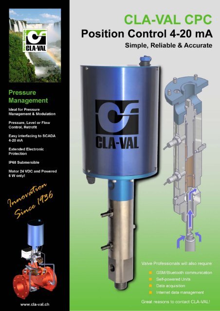
CLA-VAL <strong>CPC</strong><br />
Actuated <strong>Position</strong> <strong>Control</strong> 4-20 mA<br />
Simple, Reliable and Accurate<br />
Electronic “brushless” Motor Technology<br />
• Key Points and Description<br />
• Accurate 4-20 mA <strong>Position</strong> <strong>Control</strong> Actuator<br />
• Pressure, Level or Flow <strong>Control</strong><br />
• Easy interfacing to SCADA 4-20 mA<br />
• Submersible (IP-68)<br />
• Extended Electronic Protection<br />
• Motor 24 VDC and powered with only 6 W!<br />
The CLA-VAL <strong>CPC</strong> SERIES includes all valves with the Electronic<br />
<strong>Position</strong> Actuator. <strong>CPC</strong> provides accurate remote 4-20 mA setpoint<br />
adjustments and can adjust pressure, flow or even reservoir<br />
level by positioning the valve precisely and smoothly between the<br />
fully closed and the fully open position.<br />
Used for large water supply systems, transport pipelines or<br />
industrial applications the CLA-VAL <strong>CPC</strong> position control is a<br />
Hydraulic Actuator combined with Electronic « brushless » Motor<br />
Technology.<br />
Hydraulic Actuator<br />
Security Sensor<br />
The <strong>CPC</strong> Actuator adjusts valve operating<br />
position by controlling its lift, using hydraulic<br />
forces present in the main valve, it creates a<br />
balance between inlet, outlet and cover<br />
chamber pressure. <strong>Val</strong>ve inlet water<br />
pressure enters in the valve cover chamber<br />
through a calibrated fixed orifice. Water flows<br />
out of cover chamber to valve outlet through<br />
the stem tube and a variable orifice as<br />
illustrated in (Fig. 1). The variable orifice size<br />
is adjusted only by the <strong>CPC</strong> orifice coupling<br />
(coloured brown on Fig. 1) by the<br />
«brushless» motor, inducing the opening or<br />
the closing of the main valve. The single<br />
positioning of the orifice coupling is<br />
completely independent of the main valve<br />
diaphragm assembly and will produce<br />
identical positioning of the main valve<br />
diaphragm assembly, regardless of the<br />
system pressure.<br />
As shown in (Fig. 1) there is no mechanical<br />
link between the orifice coupling and the<br />
valve stem, which are operating as a servopiston<br />
unit. Consequently the «brushless»<br />
motor provides frictionless operation<br />
together with a very low power consumption<br />
of 6 W to move (at an adjustable speed) the<br />
orifice coupling up or down to reach any<br />
prescribed valve position, Security sensors<br />
and loss signal mode are integrated in the<br />
motor assembly.<br />
Fig. 1<br />
Motor<br />
shaft<br />
Orifice<br />
coupling<br />
Variable<br />
orifice<br />
outlet<br />
Stem<br />
tube<br />
<strong>Val</strong>ve<br />
stem<br />
CLA-VAL Europe www.cla-val.ch cla-val@cla-val.ch 1 - LIN040DE A 02/10<br />
© Copyright CLA-VAL Europe - Specifications subject to change without notice - no contractual illustrations.
CLA-VAL <strong>CPC</strong><br />
Actuated <strong>Position</strong> <strong>Control</strong> 4-20 mA<br />
How does a Hydraulically Balanced Actuator Regulate?<br />
<strong>Val</strong>ve Closing (Fig. 1)<br />
Orifice coupling<br />
Stem tube<br />
The «brushless» motor drives the orifice coupling<br />
downwards towards the requested set point which in<br />
turn decreases the variable orifice size. Subsequently<br />
less and less water discharges from the cover chamber<br />
to the valve outlet (Vs). Water flowing from the valves<br />
inlet port (Ve) enters the valve cover chamber via the<br />
calibrated fixed orifice which becomes increasingly<br />
greater than Vs generating the downward motion of the<br />
diaphragm assembly. This closes the valve to the<br />
prescribed set point corresponding to the analogical<br />
[4-20 mA] signal transmitted to the «brushless» motor.<br />
The displacement of water from the main valve<br />
diaphragm assembly is performed purely hydraulically,<br />
and there is no mechanical connection between the<br />
orifice coupling and the valve stem.<br />
In the set position, the inlet water Ve balances the<br />
discharge water Vs, which explains why any in-balance<br />
between these two values permits an immediate and<br />
smooth reaction which delivers a smooth motion of the<br />
internal diaphragm assembly.<br />
Fig. 1<br />
In the completely closed position, the leakage created<br />
by the mechanical tolerance between the orifice<br />
coupling and the stem tube is stopped drip tight at the<br />
outlet of the Electronic <strong>Position</strong> Actuator <strong>CPC</strong> by a<br />
separate solenoid valve installed in its discharge line.<br />
<strong>Val</strong>ve Opening (Fig. 2)<br />
The «brushless» motor drives the orifice coupling upwards<br />
to the requested set point which in turn increases the<br />
variable orifice size. Subsequently, more and more water is<br />
discharged from the main valve cover chamber to the valve<br />
outlet (Vs). Water entering into the valve cover Ve via the<br />
calibrated orifice is not compensating for the water leaving<br />
the top cover via Vs. This permits the diaphragm assembly<br />
to move upwards which opens the valve to the prescribed<br />
set-point corresponding to the analogical [4-20 mA] signal<br />
transmitted to the «brushless» motor. The displacement of<br />
the main valve diaphragm assembly is performed purely<br />
hydraulically, since there is no mechanical connection<br />
between the orifice coupling and the valve stem.<br />
Orifice coupling<br />
Stem tube<br />
In the set position, the inlet water Ve is balancing the water<br />
discharged via Vs, which explains why any in-balance<br />
between these two values permits an immediate and<br />
smooth reaction which delivers a smooth motion of the<br />
internal diaphragm assembly.<br />
Due to these CLA-VAL features both pressure differential<br />
values [valve inlet ⇒ cover chamber] or [cover chamber ⇒<br />
valve outlet] are identical therefore any change of pressure<br />
in the system does not affect the set position of the main<br />
valve.<br />
Fig. 2<br />
CLA-VAL Europe www.cla-val.ch cla-val@cla-val.ch 2 - LIN040DE A 02/10<br />
© Copyright CLA-VAL Europe - Specifications subject to change without notice - no contractual illustrations.
CLA-VAL <strong>CPC</strong><br />
Actuated <strong>Position</strong> <strong>Control</strong> 4-20 mA<br />
Actuated <strong>Position</strong> <strong>Control</strong> 4-20 mA features<br />
Design: The CLA-VAL <strong>CPC</strong> Actuated <strong>Position</strong><br />
<strong>Control</strong> is designed for continuous position control.<br />
The CLA-VAL <strong>CPC</strong> can be assembled on all<br />
CLA-VAL valves up to GE300/NGE400 with specific<br />
speed adjustment. Refer to specific datasheet for<br />
more information.<br />
Led indicator<br />
Power supply cable<br />
Maintenance port<br />
Input/Output cable<br />
Security high<br />
sensor<br />
Security low<br />
sensor<br />
Technical data:<br />
Software: User friendly CLA-VAL Calibration<br />
Software provides simple to program control features.<br />
4-20 mA range settings are directly entered to match<br />
desired flow or level values. The graphic interface is<br />
self explanatory and offers a very simple way to<br />
calibrate precise control values.<br />
Internet Updates: All software updates are free and<br />
available on the CLA-VAL web site.<br />
PC Connection: Plugged directly in your PC USB<br />
port or by Bluetooth e-Drive parameters and data are<br />
instantly accessible through the calibration software.<br />
PCB (Printed Circuit Board): Is build with the latest<br />
technologies including high quality components. The<br />
input is insulated (2 wires) and isolated to protect<br />
against signal interference (common mode rejection<br />
up to 1000 V). A resettable fuse is used to protect<br />
against over voltage / reverse polarity. To prevent<br />
condensation (humidity protection), heater starts<br />
when internal temp falls below 5°C, the PCB includes<br />
also tropical coating for moisture protection. The<br />
position low and high is protected automatically cuts<br />
power to prevent mechanical damage without loss of<br />
original calibration. The Brushless motor is made for<br />
continuous duty, higher efficiency and reliability.<br />
MEXUSB20401A cable and MEXUSBADAPT is<br />
required for programming and monitoring<br />
Electrical Specifications<br />
Electrical Power: • 24 VDC, 6 / 10 / 15 rpm / sizes<br />
300 mA max. load draw<br />
85 mA stand-by (no load draw)<br />
Power Protection: Max. 32 VDC over voltage<br />
Max. 1000 mA torque load<br />
Reverse polarity & short circuit<br />
80°C stop @ high temperature<br />
Led display:<br />
Green led<br />
Electrical connection: 2 x Moulded 10 m cables<br />
Input command: • 4-20 mA (2 wires)<br />
• 2x dry contact (contact security)<br />
Input 4-20 mA Max. 32 VDC over voltage<br />
Protection:<br />
Optocoupler isolation @ CMR 1000 V<br />
(CMR: common mode rejection)<br />
Insulated (2 wires)<br />
Output feedback: • 4-20 mA (Output charge ≤ 500 Ω)<br />
• 2 x programmable position alarms 24<br />
VDC / 240 VAC up to 1 A max.<br />
Output 4-20 mA<br />
Protection:<br />
Max. 32 VDC over voltage<br />
(The input dry contact and 4-20 mA<br />
output have the same common or earth<br />
but are not individually isolated)<br />
Other Specifications<br />
Sizes: GE 50 - 300 / NGE 80 - 400<br />
Operating Pressure: PN 16 bar standard<br />
Temperature range: -10°C to +80°C.<br />
Rating:<br />
IP68 standard allowing full immersion<br />
(solenoid, junction box, sensor, not<br />
included in IP68)<br />
Interface: Plug & Play / NT / 2000 / XP / Vista /<br />
Win 7<br />
Default mode<br />
Troubleshooting: Refer to user manual for LED<br />
diagnostics and codes: red-greenblinking<br />
Remote command Options available: maintain current<br />
failure:<br />
position, go to 4 mA position, go to<br />
20 mA position<br />
CLA-VAL Europe www.cla-val.ch cla-val@cla-val.ch 3 - LIN040DE A 02/10<br />
© Copyright CLA-VAL Europe - Specifications subject to change without notice - no contractual illustrations.
CLA-VAL <strong>CPC</strong><br />
Actuated <strong>Position</strong> <strong>Control</strong> 4-20 mA<br />
4 Typical applications of the CLA-VAL series <strong>CPC</strong><br />
4-20 mA Signal<br />
Upstream pressure<br />
(P1) control<br />
Downstream pressure<br />
(P2) control<br />
Rate of flow (Q)<br />
control<br />
Level (H)<br />
control<br />
The CLA-VAL <strong>CPC</strong> SERIES receives a remote analogical signal [4-20 mA] over a SCADA system or equivalent. This<br />
signal will act directly on the «brushless» motor, which will drive the orifice coupling until it reaches its corresponding set<br />
value.<br />
The <strong>CPC</strong> Actuator is particularly recommended if the user intends to apply a hydraulically operated control whilst<br />
maintaining the flexibility to change its respective set value at anytime. The applications are numerous considering the<br />
various parameters of a hydraulically operated system, whose four key applications are illustrated above and can be<br />
listed as follows :<br />
Inlet pressure control - Outlet pressure control - Rate of flow control - Level control<br />
The CLA-VAL <strong>CPC</strong> main valve offers a<br />
Characteristic curves<br />
characteristic curve extremely well<br />
adapted to a regulating process within a<br />
SCADA supervision system.<br />
In fact Fig. 1 illustrates the characteristic<br />
curves of a butterfly (green) and ball<br />
(blue) valve, as well as the one of the<br />
Q max. <strong>CPC</strong> (red) main valve. This demonstrates<br />
that the CLA-VAL <strong>CPC</strong> curve offers on<br />
one hand a much wider regulating<br />
range than the two other and on the other<br />
hand a low opening value at small rate<br />
of flow. These two conditions are the key<br />
factors for any progressive, accurate and<br />
sensible regulating operation which allows<br />
% Opening<br />
the CLA-VAL <strong>CPC</strong> to offer such a wide<br />
Fig. 1 application range.<br />
Rate of flow (l/s)<br />
CLA-VAL Europe www.cla-val.ch cla-val@cla-val.ch 4 - LIN040DE A 02/10<br />
© Copyright CLA-VAL Europe - Specifications subject to change without notice - no contractual illustrations.
CLA-VAL <strong>CPC</strong><br />
Actuated <strong>Position</strong> <strong>Control</strong> 4-20 mA<br />
4 Typical applications for the SERIES CLA-VAL <strong>CPC</strong><br />
Remote Set Point<br />
The <strong>CPC</strong> actuator receives an analogical signal (4-20 mA) from a<br />
SCADA system and automatically adjusts the «brushless» motor<br />
until the valves position reaches the prescribed set point.<br />
The <strong>CPC</strong> actuator is particularly recommended for applications<br />
where the user wishes to keep a hydraulically operated system with<br />
the ability to change the set-point of the valve. Applications are<br />
numerous depending on the types of the parameters chosen.<br />
Remote set point<br />
Local Set Point<br />
The <strong>CPC</strong> Actuator working together with an e-Smart/L2 electronic<br />
controller provides automatic control of the system. E-Smart/L2<br />
compares local feed-back signal with pre-programmed conditional<br />
set-points and adjusts the valves position automatically until set-point<br />
is reached.<br />
Feedback<br />
loop<br />
e-Smart/L2<br />
Local set point<br />
Hydraulic Safety<br />
In most <strong>CPC</strong> Actuator applications, it is possible to secure its<br />
operation during electrical power failure by additional hydraulically<br />
operated CLA-VAL pilot(s) which are added to its pilot circuit. These<br />
allow the valve to maintain a safety value. E.g Pressure reducing,<br />
pressure sustaining or maximum rate of flow until power is restored.<br />
The above combination offers the advantage of not only controlling<br />
the valve in the event of electrical power failure, but to increase the<br />
flexibility of the <strong>CPC</strong> Actuator application, by adding to the basic<br />
operation other hydraulically operated functions. These additional<br />
features for the SERIES CLA-VAL <strong>CPC</strong> are highly appreciated in<br />
applications where other variables have to be regulated during power<br />
failure.<br />
Hydraulic<br />
safety<br />
Autonomous Turbine<br />
A particular feature of the <strong>CPC</strong> Actuator is its very low power<br />
consumption with a voltage of 24 VDC. CLA-VAL has therefore taken<br />
advantage of this and developed an autonomous turbine<br />
hydraulically installed as bypass of the <strong>CPC</strong> Actuator operated valve.<br />
The turbine can feed the <strong>CPC</strong> Actuator electrical motor and<br />
eventually any other low power users, as transmission of data or<br />
specific information.<br />
The autonomous turbine, is mounted in bypass of the valve, is<br />
producing 0,5 A at 24 VDC and works in parallel with a battery,<br />
permitting actuation of the <strong>CPC</strong> motor.<br />
Autonomous<br />
turbine<br />
CLA-VAL Europe www.cla-val.ch cla-val@cla-val.ch 5 - LIN040DE A 02/10<br />
© Copyright CLA-VAL Europe - Specifications subject to change without notice - no contractual illustrations.