are study guide: graphic divisions version 3.1 - Ironwarrior.org
are study guide: graphic divisions version 3.1 - Ironwarrior.org
are study guide: graphic divisions version 3.1 - Ironwarrior.org

Create successful ePaper yourself
Turn your PDF publications into a flip-book with our unique Google optimized e-Paper software.
N C A R B<br />
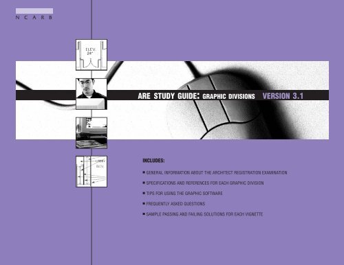
ARE STUDY GUIDE: GRAPHIC DIVISIONS VERSION <strong>3.1</strong><br />
INCLUDES:<br />
■ GENERAL INFORMATION ABOUT THE ARCHITECT REGISTRATION EXAMINATION<br />
■ SPECIFICATIONS AND REFERENCES FOR EACH GRAPHIC DIVISION<br />
■ TIPS FOR USING THE GRAPHIC SOFTWARE<br />
■ FREQUENTLY ASKED QUESTIONS<br />
■ SAMPLE PASSING AND FAILING SOLUTIONS FOR EACH VIGNETTE
ARE Study Guide: Graphic Divisions Version <strong>3.1</strong><br />
Copyright © 2005 by National Council of<br />
Architectural Registration Boards. All rights<br />
reserved. No part of this book may be<br />
reproduced, stored in a retrieval system,<br />
or transmitted for reproduction without prior<br />
permission of the publisher.<br />
Published October 2005.<br />
Updated October 2005.<br />
National Council of Architectural<br />
Registration Boards<br />
1801 K Street, NW, Suite 1100-K<br />
Washington, DC 20006<br />
202/783-6500<br />
fax: 202/783-0290<br />
www.ncarb.<strong>org</strong><br />
ISBN 0-941575-49-7<br />
Printed in the United States of America<br />
This document, effective February 2006, supersedes all previous editions of the ARE Study Guides and provides a general<br />
overview of the exam and the application, administration, and score reporting procedures. Please check NCARB’s website,<br />
www.ncarb.<strong>org</strong>, regularly for updates to the ARE Guidelines and for the most current information regarding the ARE. © 2005
TABLE<br />
OF<br />
CONTENTS<br />
Introduction................................3<br />
The ARE From Beginning to End ........5<br />
Benefits of NCARB Certification ......5<br />
Applying for the ARE ....................8<br />
Frequently Asked Questions ............9<br />
Taking the Graphic Divisions ..........12<br />
Exam Content Confidentiality ........13<br />
Site Planning ............................25<br />
Tips for Site Planning ..................26<br />
Building Planning ......................39<br />
Tips for Building Planning ............40<br />
Building Technology ....................53<br />
Tips for Building Technology ..........54<br />
10/2005<br />
ARE Study Guide: Graphic Divisions<br />
Version <strong>3.1</strong> 1
10/2005<br />
2<br />
ARE Study Guide: Graphic Divisions Version <strong>3.1</strong>
INTRODUCTION<br />
The format of this book assumes that users of this <strong>guide</strong> <strong>are</strong> prep<strong>are</strong>d<br />
to take the ARE and that they want more information on the<br />
format of the examination. The book will familiarize you with the testing<br />
environment, the softw<strong>are</strong> used to take the test, and the scoring<br />
and score reporting process. This book is not to be used as the only<br />
source for preparing for the exam as it is not intended to “teach” the<br />
architectural content of the exam’s separate test <strong>divisions</strong>. The questions<br />
included in this <strong>guide</strong> <strong>are</strong> presented to illustrate the types of<br />
<strong>graphic</strong> vignettes delivered within each division.<br />
This <strong>study</strong> <strong>guide</strong> includes a sample passing and failing solution for<br />
each of the 11 vignettes that comprise the three <strong>graphic</strong> <strong>divisions</strong> of<br />
the ARE. These sample solutions <strong>are</strong> formatted similarly to the way<br />
the vignettes appear on the actual examination. The <strong>graphic</strong>s have<br />
been reduced to fit into this book; they appear in a larger format<br />
within the exam.<br />
Prior to taking the ARE, you must be made eligible by one of<br />
NCARB’s member registration boards or one of the Canadian provincial<br />
architectural associations. It is not possible to “sign-up” for the<br />
exam with NCARB or NCARB’s testing consultant. Only individuals<br />
who have been made eligible for the ARE will be permitted to take the<br />
exam.<br />
The comments included on the sample solutions <strong>are</strong> intended to help<br />
users identify some of the positive and negative aspects of the solutions.<br />
These comments do not represent the entire evaluation<br />
process. Many deficiencies may not be noted at all; however, the<br />
overall passing or failing scores <strong>are</strong> realistic, relevant, and accurate.<br />
While the Architect Registration Examination has been designed to be<br />
taken by candidates who do not use this <strong>study</strong> <strong>guide</strong> to prep<strong>are</strong><br />
themselves, we hope that you will find it useful in your preparations<br />
for this important stage in your c<strong>are</strong>er.<br />
Practice Softw<strong>are</strong> for Graphic Divisions<br />
This <strong>study</strong> <strong>guide</strong> does not contain the practice softw<strong>are</strong> for the<br />
<strong>graphic</strong> <strong>divisions</strong>, which can be downloaded, free of charge,<br />
from the Council’s web page (www.ncarb.<strong>org</strong>).<br />
The practice program for the three <strong>graphic</strong> <strong>divisions</strong> consists of tutorials,<br />
directions, and one practice vignette for each of the 11<br />
vignettes. The tutorials have been developed to teach candidates how<br />
to use the features of the computer softw<strong>are</strong> to create solutions. You<br />
should spend as much time as necessary practicing with the softw<strong>are</strong><br />
before you take the examination, even if you feel comfortable using<br />
other computer and/or <strong>graphic</strong> drawing programs.<br />
Prior knowledge of CADD or other <strong>graphic</strong> drawing programs is not<br />
necessary. Those candidates familiar with commercially available<br />
softw<strong>are</strong> will notice differences between the drawing tools used in the<br />
examination and the softw<strong>are</strong> used in the office.<br />
Accuracy & Tolerances<br />
You <strong>are</strong> responsible for being as accurate as possible when drawing<br />
your solutions. More accurate information will result in more accurate<br />
scoring. Using the “Zoom” tool and the “Full Screen Cursor”<br />
may make it easier to produce more accurate solutions. A “Check”<br />
tool is provided in several vignettes to help you identify problem<br />
<strong>are</strong>as such as overlapping elements.<br />
Tolerances <strong>are</strong> built into each scoring program to allow for slight<br />
<strong>graphic</strong> inaccuracies. These tolerances vary from vignette to vignette<br />
based on the importance of the feature being evaluated.<br />
This <strong>guide</strong> does not contain sample<br />
questions for the six multiple-choice<br />
<strong>divisions</strong> of the ARE. Please see the<br />
companion book, ARE Study Guide:<br />
Multiple-Choice Divisions.<br />
10/2005<br />
ARE Study Guide: Graphic Divisions<br />
Version <strong>3.1</strong> 3
10/2005<br />
4<br />
ARE Study Guide: Graphic Divisions Version <strong>3.1</strong>
THE ARE FROM BEGINNING<br />
TO END<br />
10/2005<br />
The development of the Architect Registration Examination is a<br />
lengthy process that involves thousands of hours of work by hundreds<br />
of volunteer architects. Most of these volunteers <strong>are</strong> appointed<br />
to serve on various NCARB committees by NCARB’s president. Other<br />
architects volunteer their time when they complete surveys that <strong>are</strong><br />
sent out periodically to validate exam content. The examination has<br />
been written and reviewed by architects who practice in many different<br />
settings. In addition, specialists in test development have <strong>guide</strong>d<br />
the writing of new questions, the revisions to existing questions, and<br />
the formatting of the ARE. This process merges the expert judgment<br />
of architects with the expertise of test developers.<br />
The ARE is designed to measure minimum competence of the knowledge,<br />
skills, and abilities that architects must possess in order to<br />
safely practice architecture independently. In order to best determine<br />
the content of the ARE, NCARB employs a number of procedures<br />
that <strong>are</strong> widely used in the testing of professionals such as accountants,<br />
physicians, lawyers, and others. Periodically, NCARB surveys<br />
thousands of architects to determine what knowledge, skills, and<br />
abilities <strong>are</strong> used by newly registered architects in their practice. This<br />
survey, known as a “practice analysis,” identifies tasks performed by<br />
architects that <strong>are</strong> the most important in protecting the public health,<br />
safety, and welf<strong>are</strong>. It is important to keep in mind that the ARE is<br />
not intended to be a test covering all possible tasks an architect may<br />
be called on to perform; rather, it focuses on those tasks deemed<br />
most important from a public-protection point of view.<br />
NCARB uses the results of the practice analysis survey as the basis for<br />
developing specifications for each division of the ARE. The architects<br />
who volunteer their time and expertise to write test questions and<br />
<strong>graphic</strong> vignettes follow these specifications. Checks and balances in<br />
the development process prevent volunteers from interjecting their<br />
own personal perspectives into the ARE. Just as in the development of<br />
construction specifications, these test specifications <strong>are</strong> strictly followed<br />
and <strong>are</strong> not changed without significant research and analysis.<br />
Several times a year, the ARE Subcommittee, a group of approximately<br />
60 architects, meets to write new multiple-choice questions,<br />
create <strong>graphic</strong> vignettes, and review and pretest existing questions<br />
and vignettes. These architects <strong>are</strong> first trained in writing test questions<br />
for a registration examination, which differs greatly from writing<br />
questions for other types of exams. This training is conducted<br />
by NCARB’s consultant, Thomson Prometric. During<br />
each committee meeting, staff members from Thomson<br />
Prometric work with the architects and <strong>guide</strong> them through<br />
the process. Following the subcommittee’s work, NCARB’s<br />
staff architects and Thomson Prometric’s staff format and prep<strong>are</strong><br />
the questions and vignettes for delivery on computer. The ARE<br />
Subcommittee reviews the packaged exams before they <strong>are</strong> delivered<br />
to candidates.<br />
One of the most important things to understand about this process is<br />
that the test is designed by architects and prep<strong>are</strong>d by architects.<br />
Therefore, it is a practice-based exam and not a test of book knowledge<br />
or material learned in the academic environment. There is no substitute<br />
for a well-rounded internship to help prep<strong>are</strong> you for the ARE.<br />
Graphic Divisions<br />
The ARE includes three <strong>divisions</strong> administered in a <strong>graphic</strong> format.<br />
The three <strong>divisions</strong> test architectural content in the <strong>are</strong>as of Site<br />
Planning, Building Planning, and Building Technology. Each is composed<br />
of a series of vignettes. The Site Planning division consists of<br />
three vignettes, the Building Planning division has two vignettes, and<br />
the Building Technology division has six vignettes.<br />
Each of the three <strong>graphic</strong> <strong>divisions</strong> will be administered within a fixed<br />
maximum time limit. Every candidate will take all of the vignettes<br />
within a division, and every candidate will have the same amount of<br />
time for each division. Your scheduled appointment time is longer<br />
than your actual test time in order to accommodate checking in at<br />
the test center, answering demo<strong>graphic</strong> questions, and taking a<br />
scheduled break.<br />
The practice softw<strong>are</strong> is available for downloading from NCARB’s web<br />
site at www.ncarb.<strong>org</strong>. It allows you to practice using the test-delivery<br />
softw<strong>are</strong> on all of the vignettes within the three <strong>graphic</strong> <strong>divisions</strong>.<br />
As is the case with the multiple-choice <strong>divisions</strong>, the <strong>graphic</strong> <strong>divisions</strong><br />
<strong>are</strong> administered year-round; therefore, many <strong>version</strong>s of each<br />
vignette <strong>are</strong> available to draw from to assemble each candidate’s particular<br />
exam. When you take your exam, one of each different<br />
vignette type will be selected randomly from the pool of available<br />
Benefits of NCARB Certification<br />
After successful completion of the examination<br />
and licensure process, many newly<br />
registered architects find it necessary to<br />
become registered in other jurisdictions.<br />
Typically, this means completing new<br />
forms from the second registration board<br />
documenting your education, employment,<br />
references, and exam scores because<br />
boards do not accept copies of other<br />
boards’ application forms. NCARB has<br />
developed a certification system that<br />
makes this process much easier.<br />
Almost half of the 55 NCARB member registration<br />
boards require an NCARB<br />
Certificate for interstate registration.<br />
NCARB certification is also used to facilitate<br />
reciprocity between U.S. and Canadian<br />
jurisdictions. The Certificate is granted to<br />
those architects who <strong>are</strong> registered by an<br />
NCARB member board or Canadian provincial<br />
association, and whose NCARB Council<br />
Record has been compiled and evaluated<br />
to ensure that NCARB’s standards for certification<br />
have been met.<br />
Maintaining a record of your qualifications<br />
is one of many services that NCARB provides.<br />
The Council Record is a detailed,<br />
authenticated record of your education,<br />
training, examination, registration, and<br />
character. This confidential record consists<br />
ARE Study Guide: Graphic Divisions<br />
Version <strong>3.1</strong> 5
Benefits of NCARB Certification (cont’d.)<br />
of school transcripts, employment verifications,<br />
architect verifications, and examination<br />
and registration history. In order to be<br />
issued an NCARB Certificate, you must<br />
comply with the Council’s standards as set<br />
collectively by NCARB’s member boards.<br />
As long as your Certificate is in good<br />
standing and the transmittal fee has been<br />
paid, NCARB will transmit your Certificate<br />
Record to any member board or foreign<br />
registration authority in support of your<br />
application for registration. The Certificate<br />
Record–your Council Record along with<br />
certification–signifies to registration<br />
authorities that you have met NCARB’s<br />
certification standards.<br />
In order to request a transmittal of your<br />
Council Record, you should call the<br />
Council, visit NCARB’s web site<br />
(www.ncarb.<strong>org</strong>), or write the NCARB<br />
office. Please include your file number,<br />
daytime phone number, fax number, and<br />
the name of the jurisdiction(s) to which<br />
you <strong>are</strong> requesting a transmittal of your<br />
Council Record.<br />
Unlike a license, an NCARB Certificate<br />
does not entitle you to practice architecture<br />
in a jurisdiction. It also does not indicate<br />
membership in NCARB; rather, it<br />
stands as a testimony to your qualifications<br />
as an architect. The Certificate carries<br />
the recommendation that you should be<br />
registered as an architect without additional<br />
submissions or examination, although a<br />
few states may require you to demonstrate<br />
your competency in additional <strong>are</strong>as such<br />
as arctic construction or local laws. These<br />
additional requirements may be found in<br />
the Member Board Requirements section<br />
of NCARB’s web site.<br />
vignettes. Each vignette is similar and equal in difficulty to all others of<br />
its type so that you will not be asked to do more or less work than any<br />
other candidate on a particular vignette. This is achieved through tight<br />
control of the test specification during development.<br />
The <strong>graphic</strong> <strong>divisions</strong> <strong>are</strong> administered in sections to allow for a brief<br />
break during the testing process. A section comprises a group of<br />
vignettes or a single vignette that you <strong>are</strong> able to view and work on at<br />
a given time. For sections containing multiple vignettes you may work<br />
on the vignettes within that section in any order you choose, and you<br />
may take as much time as you need on each vignette up to the maximum<br />
time allotted for that section. Vignettes within a section may be<br />
reviewed; however, when the alotted time for the section is up, or if<br />
you exit the section, you will not be able to return to any vignette in<br />
that section.<br />
After you complete all vignettes within a division, the electronic record<br />
of your examination will be sent to NCARB’s testing consultant for<br />
grading. After your test is graded and all quality-control procedures<br />
have been completed, a score report is provided to your registration<br />
board who will then forward it to you.<br />
Multiple-Choice Divisions<br />
The ARE includes six multiple-choice <strong>divisions</strong> administered in a fixedlength<br />
format. The six <strong>divisions</strong> test architectural content in the <strong>are</strong>as<br />
of Pre-Design, General Structures, Lateral Forces, Mechanical<br />
& Electrical Systems, Building Design / Materials & Methods, and<br />
Construction Documents & Services.<br />
The multiple-choice <strong>divisions</strong> contain varying numbers of questions.<br />
See the chart on page 12 of the ARE Study Guide: Multiple Choice<br />
Divisions for a breakdown of questions and test times for each division.<br />
The question number and your remaining test time will be displayed<br />
on the computer screen throughout your exam.<br />
For each test question, you will be presented with four choices, one of<br />
which is clearly the best answer. Questions will be presented one at a<br />
time, and you will have the ability to skip the question, answer the<br />
question, or answer the question and mark it for later review. You can<br />
move backward and forward through the exam using arrow icons that<br />
appear on the screen, or you can navigate to a specific point in the<br />
exam by choosing the “Review” feature.<br />
Regardless of your approach, it is important to answer every question.<br />
Any question not answered will be counted as incorrect; therefore,<br />
guessing may help your overall score.<br />
Within each of the six multiple-choice <strong>divisions</strong> of the ARE, the test<br />
questions you receive will differ from those your colleagues receive.<br />
Since the ARE is administered year-round, test questions <strong>are</strong> issued<br />
randomly to preserve the test’s security. Therefore, the test questions<br />
<strong>are</strong> <strong>org</strong>anized to allow each administration to cover the same test content<br />
as all other administrations and to be of the same average difficulty<br />
as all other administrations.<br />
In order for NCARB to know the average difficulty of a test, each question<br />
must have been administered to a large number of candidates.<br />
These “pretest” questions <strong>are</strong> scattered throughout each test so that<br />
statistical information can be collected on the questions for use in<br />
future exams. These questions do not count toward your final score.<br />
When your test is complete, the electronic record of your examination<br />
will be sent to NCARB’s testing consultant to undergo quality-control<br />
procedures. Following these checks, a score report will be provided to<br />
the registration board that made you eligible for the ARE. The board<br />
will then forward the score report to you.<br />
All Divisions<br />
You will receive a separate score report for each ARE division in the<br />
mail. Test scores <strong>are</strong> not available at the test center. The score report<br />
will indicate whether you passed or failed the division; no numeric<br />
scores <strong>are</strong> reported. In the event a failing score is reported, your score<br />
report will indicate relative strengths and weaknesses in each portion<br />
of the test specification. The ARE is not a test of luck. If you fail a division,<br />
you will need to increase your knowledge and experience level in<br />
those <strong>are</strong>as determined to be weakest before you take the test again.<br />
The limited diagnostic information provided can be used to plan for<br />
additional training and <strong>study</strong> before repeating the division.<br />
If you do not pass a division you must wait six months before you repeat<br />
that division. You will receive a new Authorization to Test for each failed<br />
division approximately two months before the end of the mandatory waiting<br />
period so that you may schedule a new appointment.<br />
10/2005<br />
6<br />
ARE Study Guide: Graphic Divisions Version <strong>3.1</strong>
Maintaining Exam Eligibility<br />
You <strong>are</strong> responsible for maintaining your exam eligibility with your<br />
registration board. Consequently, you should be aw<strong>are</strong> of the specific<br />
rules your board has for maintaining eligibility. Some boards require<br />
you to pay an annual maintenance fee so they do not cancel scores<br />
for <strong>divisions</strong> you passed should your eligibility expire.<br />
Because the rules vary from board to board and <strong>are</strong> subject to frequent<br />
change, NCARB cannot be responsible if you take a division of<br />
the ARE at a time when your board has canceled your eligibility. Your<br />
scores may be canceled for the <strong>divisions</strong> taken when your eligibility<br />
has expired, and you will not be eligible for a refund of test fees.<br />
Therefore, it is important for you to stay informed of your individual<br />
registration board’s policies and procedures. This includes notifying<br />
them of any address changes so they can contact you about eligibility<br />
renewals or any other important licensure information and so that<br />
NCARB can contact you regarding any updates about the exam.<br />
Rolling Clock<br />
During NCARB’s 2004 Annual Meeting, the Council passed a resolution<br />
officially creating a “rolling clock” requirement for the ARE.<br />
Under the terms of the Rolling Clock, which will be officially implemented<br />
on January 1, 2006, candidates for the ARE must pass all<br />
<strong>divisions</strong> within five years. Three transitional rules, which <strong>are</strong> noted<br />
below, will <strong>guide</strong> the process.<br />
Rules<br />
Three basic rules will <strong>guide</strong> the implementation of the Rolling Clock:<br />
■ For applicants who have passed all <strong>divisions</strong> of the<br />
ARE by January 1, 2006, regardless of the time<br />
taken, such applicants will have passed the ARE.<br />
■ For applicants who have passed one or more but not<br />
all <strong>divisions</strong> of the ARE by January 1, 2006, such<br />
applicants will have five years from the date of the first<br />
(non-exempt) passed division to pass all remaining<br />
<strong>divisions</strong>. [Exams passed prior to January 1, 2006, <strong>are</strong><br />
exempt and will NOT have to be retaken.] If a candidate<br />
fails to pass all remaining <strong>divisions</strong> within the initial fiveyear<br />
period, the candidate is given a new five-year period<br />
from the date of the second oldest passed division. The<br />
five-year period shall commence after January 1, 2006, on<br />
the date when the first passed division is administered.<br />
■<br />
For applicants who have passed no <strong>divisions</strong> of the ARE<br />
by January 1, 2006, such applicants shall be governed by the<br />
above five-year requirement. The five-year period shall commence<br />
on the date when the first passed division is<br />
administered.<br />
Adherance to these rules is required for NCARB Certification.<br />
Units of Measurement<br />
The ARE includes both inch-pound and SI (Système<br />
International) units commonly referred to as metric units. References<br />
to applicable Canadian documents, standards, and terms <strong>are</strong> also<br />
included.<br />
For most questions in the six multiple-choice <strong>divisions</strong>, SI units and<br />
Canadian standards and terms appear in brackets immediately following<br />
the inch-pound units and U.S. standards and terms. Con<strong>version</strong>s<br />
to SI units <strong>are</strong> approximate and have been rounded for simplicity and<br />
clarity. You must complete your work in either inch-pound units or<br />
metric (SI) units, where appropriate. Converting from one system to<br />
another may result in wrong answers.<br />
You will be given the opportunity to choose to work in either inchpound<br />
units or metric units at the beginning of each <strong>graphic</strong> division.<br />
Once you have made a choice and confirmed your selection, your<br />
decision is final and cannot be changed during your examination. All<br />
of the dimensions and references to standards on the drawings and<br />
in the written materials will be displayed in the measurement system<br />
selected.<br />
French-Language Examinations<br />
If you <strong>are</strong> seeking initial registration with one of the Canadian provincial<br />
or territorial architectural associations, you have the option of<br />
writing the ARE in either French or English.<br />
If you want to write the ARE in French, you must notify your<br />
provincial or territorial association. If, in the future, you wish to<br />
change your language preference, you must notify your provincial or<br />
territorial association. French-language examinations <strong>are</strong> ONLY available<br />
at test centers in Canada. The French-language <strong>graphic</strong> <strong>divisions</strong><br />
use metric units only. Candidates seeking initial registration with any<br />
U.S. board of architecture must complete the ARE in English.<br />
Benefits of NCARB Certification (cont’d.)<br />
There <strong>are</strong> many reasons to begin compiling<br />
your Council Record early in your c<strong>are</strong>er.<br />
Relevant employment must be<br />
verified in order to be eligible for<br />
certification. By starting the record<br />
compilation process now, you can<br />
document your experience as it is<br />
earned and take advantage of special costsaving<br />
options for the program.<br />
If, after receiving your initial registration,<br />
you <strong>are</strong> interested in applying for NCARB<br />
certification, you can obtain the necessary<br />
forms and information by calling<br />
NCARB’s Council Records Department<br />
at 202/879-0520 or by visiting the<br />
Council’s web site (www.ncarb.<strong>org</strong>).<br />
10/2005<br />
ARE Study Guide: Graphic Divisions<br />
Version <strong>3.1</strong> 7
APPLYING FOR THE ARE<br />
The Architect Registration Examination, like other professional registration<br />
examinations, is administered for local jurisdictions (states,<br />
provinces, and territories) as partial fulfillment of the requirements<br />
for professional registration. As such, there is no national or multinational<br />
process for signing up to take the exam. Candidates must<br />
contact the registration board where they wish to be initially registered<br />
and meet that board’s requirements for registration. Many<br />
boards currently require applicants to hold an accredited professional<br />
degree in architecture and have at least three years of experience in<br />
the offices of registered architects before they <strong>are</strong> allowed to begin<br />
the examination process. However, this is not the case in all jurisdictions.<br />
These requirements vary by jurisdiction, so it is wise to learn<br />
about them as early as possible. A brief summary of jurisdictional<br />
requirements is available on the Council’s web site at www.ncarb.<strong>org</strong>.<br />
In many cases, candidates in the United States will be required to<br />
complete the Intern Development Program (IDP) prior to becoming<br />
eligible to sit for the ARE. Canadian provinces require completion of<br />
the Canadian Intern Architect Program training requirements before<br />
taking the ARE.<br />
It is, unfortunately, all too common for candidates to wait until they<br />
have completed five or more years of education and three years of<br />
internship to ask about the requirements for their jurisdiction, only to<br />
find they do not have the required degree or experience to become<br />
registered.<br />
The typical application process consists of documenting transcripts,<br />
work experience, and professional references. This process can take<br />
many months to complete, especially if you have attended more than<br />
one university and/or had many employers. If you have completed the<br />
IDP or the Canadian IAP, you will find the exam-application process is<br />
relatively easy since most of the required documents have been compiled<br />
over the course of your internship. Please see NCARB’s most<br />
recent edition of the IDP Guidelines or go to www.ncarb.<strong>org</strong> to learn<br />
more about IDP.<br />
When you have met all of your registration board’s requirements, your<br />
board will submit your eligibility information to NCARB’s testing consultant,<br />
Thomson Prometric. Thomson Prometric will then send you all the<br />
information you need to begin scheduling your examinations, including<br />
your Authorization to Test form, a listing of test centers, and the ARE<br />
Guidelines. The practice program may be downloaded, free of charge, at<br />
www.ncarb.<strong>org</strong>. Candidates <strong>are</strong> encouraged to frequently check NCARB’s<br />
web site to download the latest <strong>version</strong> of the practice program.<br />
Individuals with disabilities who may require special testing accommodations<br />
should contact their registration board directly, or NCARB<br />
if your registration board participates in the Direct Registration<br />
Program. Please refer to the ARE Guidelines to determine if your<br />
jurisdiction participates in the program.<br />
Direct Registration<br />
The Direct Registration program is a service provided to Member<br />
Boards. For those Boards participating in the program, NCARB temporarily<br />
serves as an intermediary and manages all candidate eligibility<br />
and score reporting processes. Please refer to the inside back<br />
cover of this publication to determine if your jurisdiction participates<br />
in the program.<br />
10/2005<br />
8<br />
ARE Study Guide: Graphic Divisions Version <strong>3.1</strong>
How many <strong>divisions</strong> make-up the ARE?<br />
The ARE consists of nine <strong>divisions</strong> - six multiple-choice <strong>divisions</strong> and<br />
three <strong>graphic</strong> <strong>divisions</strong>. The multiple-choice <strong>divisions</strong> <strong>are</strong>: Pre-Design,<br />
General Structures, Lateral Forces, Mechanical & Electrical Systems,<br />
Building Design / Materials & Methods, and Construction Documents<br />
& Services. The <strong>graphic</strong> <strong>divisions</strong> <strong>are</strong> Site Planning, Building<br />
Planning, and Building Technology.<br />
Who writes the ARE?<br />
The exam is written by dozens of architects from NCARB’s member<br />
registration boards, consulting engineers, and code officials.<br />
Canadian architects from the Committee of Canadian Architectural<br />
Councils (CCAC) representing the architectural associations of the<br />
Canadian provinces also serve on exam-writing committees.<br />
Individual exam-writing committees for each division of the exam<br />
meet several times a year to revise and write questions and vignettes<br />
used in the exam.<br />
How do I register to take the ARE?<br />
Contact the registration board in your state/province to apply to take<br />
the exam. Your board will provide you with all application requirements.<br />
Although NCARB prep<strong>are</strong>s the ARE, it does not register candidates<br />
to take the exam. If your board requires documentation of the<br />
IDP (Intern Development Program), they will instruct you to establish<br />
an IDP record with NCARB.<br />
How do I start taking the ARE?<br />
1. If you began taking the exam in paper-and-pencil format, your<br />
registration board may or may not require you to apply to them<br />
to continue taking the ARE; you need to contact them to<br />
determine this.<br />
2. Once you <strong>are</strong> eligible to take the ARE, your registration board will<br />
submit your name to NCARB’s eligibility database. If your Board<br />
participates in the Direct Registration program, NCARB temporarily<br />
serves as an intermediary and manages all candidate eligibility<br />
and score reporting processes. Please refer to the ARE Guidelines<br />
to determine if your jurisdiction participates in the program. This<br />
publication can be downloaded from the Council’s web site at<br />
www.ncarb.<strong>org</strong>.<br />
4. The practice program may be downloaded, free of charge, from<br />
the Council’s web site (www.ncarb.<strong>org</strong>). Candidates <strong>are</strong><br />
encouraged to frequently check NCARB’s web site to<br />
download the latest <strong>version</strong> of the practice program.<br />
5. After you receive the ARE Guidelines, decide when and<br />
where you want to take your exams and call to schedule a<br />
test appointment.<br />
When is the computer-based exam given?<br />
You have the opportunity to take the exam in any order at any time<br />
you choose once you have been approved to take the exam. Test centers<br />
<strong>are</strong> open Monday through Saturday, but hours vary from test<br />
center to test center. Contact the test center of your choice to determine<br />
their hours of operation.<br />
Where <strong>are</strong> the test centers located?<br />
The ARE is administered at approximately 300 standardized test centers<br />
across North America. Once your eligibility information has been<br />
processed, Thomson Prometric will send you a listing of test centers<br />
and contact information.<br />
Do I have to take all nine <strong>divisions</strong> of the ARE within one week,<br />
as was the case with the paper-and-pencil ARE?<br />
No. You can take the <strong>divisions</strong> at any time during your eligibility period.<br />
Do I have to take the exam at a test center within the borders<br />
of the state or province where I am seeking my initial license<br />
(registration)?<br />
No. NCARB’s computer-based format removes geo<strong>graphic</strong>al barriers.<br />
For instance, a candidate who started taking the exam in Texas, and<br />
now lives in New York, will be able to take the exam at any conveniently<br />
located test center, rather than having to return to Texas.<br />
Scores will be forwarded to the initial jurisdiction where you <strong>are</strong> seeking<br />
registration.<br />
FREQUENTLY ASKED<br />
QUESTIONS ABOUT<br />
THE ARE<br />
National Council of Architectural<br />
Registration Boards<br />
1801 K Street, NW, Suite 1100-K<br />
Washington, DC 20006<br />
202/783-6500<br />
202/783-0290 Fax<br />
www.ncarb.<strong>org</strong><br />
Committee of Canadian<br />
Architectural Councils<br />
6 Wheeler Street<br />
Nepean, Ontario K2J 3C1<br />
CANADA<br />
613/825-2660<br />
ARE Operations<br />
P.O. Box 6542<br />
Princeton, NJ 08540<br />
800/896-2272<br />
800/692-5395 TTY<br />
609/895-5022 Fax<br />
10/2005<br />
3. NCARB’s consultant, Thomson Prometric, will send you a test<br />
information package that includes: the ARE Guidelines, which<br />
describes test content, timing for each division, test fees, and<br />
payment information for the exam; a list of test centers where<br />
you can take the exam; and your Authorization to Test form.<br />
ARE Study Guide: Graphic Divisions<br />
Version <strong>3.1</strong> 9
Thompson Prometric Candidate<br />
Services Contact Center<br />
800/479-6215<br />
800/529-3590 TTY<br />
800/967-1139 Special Conditions<br />
www.prometric.com<br />
for centers near you or<br />
to schedule online<br />
What is the Rolling Clock?<br />
Beginning January 1, 2006, NCARB will implement a “Rolling Clock.”<br />
Under the “Rolling Clock,” candidates must pass all ARE <strong>divisions</strong><br />
within five years. For further details, please refer to NCARB’s website,<br />
www.ncarb.<strong>org</strong>.<br />
Will a calculator be provided at the test center?<br />
Calculators will not be provided at the test center. However, the<br />
<strong>graphic</strong> <strong>divisions</strong> have a calculator built into the softw<strong>are</strong> interface.<br />
check NCARB’s web site to download the latest <strong>version</strong> of the practice<br />
program. Make sure you allow sufficient time prior to testing to<br />
become familiar with the softw<strong>are</strong> you will be using.<br />
For the vignettes in the three <strong>graphic</strong> <strong>divisions</strong>, how will we<br />
“draw” on the computer?<br />
You will use a mouse to record your solutions. The computer screen<br />
contains icons that <strong>are</strong> selected using the mouse, to allow you to<br />
draw, move, rotate, erase, etc.<br />
Hours of Operation<br />
Monday—Friday<br />
8:00 a.m. to 8:00 p.m. ET<br />
Direct Registration<br />
The Council recently introduced the Direct<br />
Registration program as a new service<br />
provided to registration boards. For those<br />
boards participating in the program,<br />
NCARB temporarily serves as an intermediary<br />
and manages all candidate eligibility<br />
and score reporting processes.<br />
For multiple-choice <strong>divisions</strong>, you must bring your own scientific<br />
calculator to the test center. ONLY non-programmable, non-communicating,<br />
non-printing calculators <strong>are</strong> allowed. It must NOT have preloaded<br />
formulas or have the capability to store formulas. The test<br />
center administrator reserves the right to refuse the use of any other<br />
calculators and is not responsible for providing a replacement calculator.<br />
For the <strong>graphic</strong> <strong>divisions</strong> of the exam, will I be able to stop working<br />
on one vignette and move to another, then come back to the<br />
first vignette?<br />
Yes. You <strong>are</strong> able to stop working on one vignette, move to a second<br />
or third vignette, come back to the first, etc., within each section of<br />
vignettes. However, once you choose to exit that section of vignettes,<br />
you cannot return to them. You do not need to save your work, as it<br />
is automatically saved approximately every minute. Every time you<br />
leave a vignette to move to another vignette your work is also saved.<br />
Will I be able to print out my solutions as I go to check them?<br />
You <strong>are</strong> not able to print out your work. In order to offer the ARE six<br />
days a week, year-round, NCARB has developed a large library of<br />
equivalent vignettes. These vignettes must remain secure, so printouts<br />
<strong>are</strong> not allowed.<br />
What softw<strong>are</strong> will be used, and how can I get it to practice?<br />
The softw<strong>are</strong> used to take the exam is not commercially available.<br />
NCARB did this for two reasons. First, the exam might unfairly<br />
advantage one group of candidates that was familiar with the softw<strong>are</strong><br />
and disadvantage the remaining candidates. Second, the softw<strong>are</strong><br />
NCARB has developed is designed for testing and not for the<br />
creation of construction documents. The softw<strong>are</strong> is much more intuitive<br />
than CAD packages. The practice program includes tutorials to<br />
teach you how to use the various tools, plus one of each of the<br />
vignettes to practice. You may download the current <strong>version</strong>, free of<br />
charge, at www.ncarb.<strong>org</strong>. Candidates <strong>are</strong> encouraged to frequently<br />
How will the multiple-choice <strong>divisions</strong> be given on a computer?<br />
A brief tutorial is delivered before each division to explain how to<br />
move from one question to the next. Each multiple-choice division<br />
consists of a fixed number of questions delivered within a maximum<br />
time limit. Within each division, some questions <strong>are</strong> being pretested<br />
and do not affect your actual test score. These pretest questions <strong>are</strong><br />
being evaluated and may be included in future editions of the test.<br />
For the multiple-choice questions, I’ve heard that I will only be<br />
able to look at one question at a time and I will not be able to go<br />
back to previous questions to change answers. Is this true?<br />
It is true that you will only see one question at a time; however, you<br />
can go back to review and/or change answers. You will have tools<br />
(icons) available to maneuver through the test. It is possible to look<br />
at each question, answer it, and move on without going back. It is<br />
also possible to answer a question and mark it for later review.<br />
Additionally, you will have the option to skip a question and come<br />
back to it later.<br />
How <strong>are</strong> the vignettes scored?<br />
The vignettes <strong>are</strong> scored by computer.<br />
How can the subjective vignettes be graded by computer? Does<br />
this mean that there is only one right answer to each vignette?<br />
There have been many common misconceptions about the ARE. One<br />
of the biggest was that the paper-and-pencil vignettes were graded<br />
using “subjective” criteria. In the past, NCARB developed very specific<br />
objective grading criteria and trained the architects who volunteered<br />
to grade exams in using this objective criteria. NCARB never<br />
allowed the graders to apply their own subjective criteria to exams.<br />
With computer grading, the only real change is that committees of<br />
architects have already determined the objective grading criteria, and<br />
that criteria has been transferred to a computer program instead of<br />
human graders.<br />
10/2005<br />
10<br />
ARE Study Guide: Graphic Divisions Version <strong>3.1</strong>
10/2005<br />
The computer-delivered vignettes, like the paper-and-pencil vignettes,<br />
<strong>are</strong> designed to allow for many correct answers. There is no one right<br />
answer, with the exception of some very technical Site Planning<br />
vignettes, such as laying out setbacks. Just as in the paper-and-pencil<br />
<strong>version</strong>s, the vignette scoring procedures allow for errors to occur<br />
without automatically assigning a failing score. The scoring engines<br />
evaluate the solutions to the vignettes in a holistic manner where<br />
minor errors <strong>are</strong> compensated for by overall compliance with the<br />
programmatic and technical aspects of each vignette.<br />
How long after I take the exam will I receive my scores?<br />
Results for multiple-choice <strong>divisions</strong> <strong>are</strong> typically processed within two<br />
to four weeks of your test date. Graphic division scores <strong>are</strong> typically<br />
processed within four to six weeks of your test date. After processing,<br />
your score is forwarded directly to your Board of Architecture or<br />
NCARB if your board participates in the Direct Registration Program.<br />
Your board then completes any additional processing and forwards the<br />
score report to you. Test results <strong>are</strong> not released at the test center and<br />
<strong>are</strong> not available through NCARB.<br />
If I fail a division of the exam, why do I have to wait six months<br />
until I can retake that division?<br />
This rule was established for two reasons. First, the exams <strong>are</strong> not a<br />
test of luck. It is important to spend the time between test administrations<br />
gaining additional knowledge and experience in the particular<br />
<strong>are</strong>as being tested. Second, NCARB is developing a large library of test<br />
questions and vignettes, but the library is not of sufficient size to offer<br />
each division of the exam more than once every six months.<br />
For the last two administrations of a particular division, I received<br />
the same failing diagnostics. What can I do to improve my score<br />
and pass?<br />
Receiving similar score reports indicates that the exam has accurately<br />
assessed your ability level at the time. In order to pass, you will have<br />
to gain additional knowledge in the subject <strong>are</strong>a before trying again.<br />
Repeating a division without increasing your knowledge of the subject<br />
through more experience will likely not result in a higher score.<br />
I failed the paper-and-pencil Building Design exam. Do I have to<br />
take one or two tests in the new format?<br />
Two. The old Division C: Building Design exam is now two separate<br />
<strong>divisions</strong>–Building Planning and Building Technology. NCARB<br />
made this change because sitting at a computer for 11 or 12<br />
hours is much more difficult than sitting at a drawing table for<br />
that amount of time. You must pass these two <strong>divisions</strong> completely<br />
independent of each other.<br />
I failed the Site Design <strong>graphic</strong> portion in paper-and-pencil, but<br />
passed the written portion. Do I get credit for the written portion?<br />
No. Since you did not pass both sections of the previous Division B:<br />
Site Design, you must take the new Site Planning division.<br />
If I pass all <strong>divisions</strong> of the ARE, does that mean I am certified by<br />
NCARB?<br />
No. Passing the exam is usually (but not always) the final step in<br />
receiving a license to practice in a particular jurisdiction. If you wish to<br />
become certified by NCARB, you must apply for NCARB certification<br />
after you have passed the exam, or contact NCARB’s Council Records<br />
Department if you have already established an IDP Council Record.<br />
Your state board will not notify NCARB. For more information on the<br />
certification process, contact NCARB’s Council Records Department at<br />
202/879-0520. You also can get more information or request an application<br />
by visiting NCARB’s web site (www.ncarb.<strong>org</strong>).<br />
Review and Challenge<br />
A review procedure is available to you<br />
ONLY if your Board of Architecture permits<br />
reviews of failed examinations. It is at<br />
the sole discretion of each Board of<br />
Architecture whether or not to administer<br />
the review process. If you wish<br />
to pursue the review process, immediately<br />
contact your Board of Architecture<br />
to better understand the procedures and<br />
fees involved. The application for review<br />
must be completed within four months of<br />
the administration of your test date, and<br />
the review process must be completed<br />
within six months of your test date.<br />
Only those questions you answered incorrectly<br />
or those vignettes marked with an<br />
asterisk (*) on your score report can be<br />
reviewed. The correct answer or proper<br />
solution will not be revealed.<br />
During the review process, you may only<br />
challenge a question answered incorrectly<br />
for a multiple-choice division. A representative<br />
from your board will forward your<br />
challenge to a multiple-choice question to<br />
NCARB for review and response. Any challenge<br />
to a <strong>graphic</strong> vignette will not be<br />
reviewed by NCARB.<br />
Depending on the laws of the jurisdiction<br />
where you <strong>are</strong> seeking registration, you<br />
may be able to challenge the score received<br />
on any ARE division. If your Board of<br />
Architecture (or a court with jurisdiction)<br />
changes your score from fail to pass, ONLY<br />
that jurisdiction is required to accept the<br />
new score. NCARB will not recognize the<br />
new score for purposes of NCARB<br />
certification.<br />
ARE Study Guide: Graphic Divisions<br />
Version <strong>3.1</strong> 11
TAKING THE<br />
GRAPHIC DIVISIONS<br />
TEST TIMING<br />
Pages 5-7 of this book describe the format<br />
used to administer the <strong>graphic</strong> <strong>divisions</strong> of<br />
the ARE. The chart to the right shows the<br />
amount of actual test time allowed within<br />
each group of vignettes, the recommended<br />
time for each vignette, and the total scheduled<br />
appointment time. The scheduled<br />
appointment time includes time for general<br />
instructions and an exit evaluation survey.<br />
GRAPHIC DIVISIONS<br />
MAXIMUM RECOMMENDED SCHEDULED<br />
DIVISION SECTION TIME VIGNETTE TIME APPOINTMENT TIME<br />
SITE PLANNING<br />
3.75 HOURS<br />
SECTION 1 1.5 HOURS SITE DESIGN 1 HOUR 30 MINUTES<br />
15 MINUTE BREAK<br />
1.5 HOURS SITE ZONING 1 HOUR<br />
SECTION 2<br />
SITE GRADING 30 MINUTES<br />
BUILDING PLANNING<br />
SECTION 1<br />
SECTION 2<br />
BUILDING TECHNOLOGY<br />
1 HOUR INTERIOR LAYOUT 1 HOUR<br />
15 MINUTE BREAK<br />
4 HOURS SCHEMATIC DESIGN 4 HOURS<br />
5.75 HOURS<br />
6 HOURS<br />
BUILDING SECTION<br />
1 HOUR<br />
SECTION 1<br />
SECTION 2<br />
STRUCTURAL LAYOUT 45 MINUTES<br />
2.5 HOURS ACCESSIBILITY/RAMP 45 MINUTES<br />
15 MINUTE BREAK<br />
2.75 HOURS MECH & ELEC PLAN 1 HOUR<br />
STAIR DESIGN<br />
ROOF PLAN<br />
1 HOUR<br />
45 MINUTES<br />
SCORE REPORTS ARE PROCESSED ➔ GRAPHIC DIVISIONS ➔ 4-6 WEEKS<br />
10/2005<br />
12<br />
ARE Study Guide: Graphic Divisions Version <strong>3.1</strong>
EXAM CONTENT<br />
CONFIDENTIALITY<br />
All NCARB tests <strong>are</strong> held in strict<br />
security and confidence. Before<br />
beginning your test, you will be<br />
required to accept a confidentiality<br />
statement, which prohibits any<br />
disclosure of exam content.<br />
By taking <strong>divisions</strong> of the ARE, you <strong>are</strong> personally<br />
responsible for maintaining the<br />
confidentiality of all information relating to<br />
the exam. You may not discuss exam content<br />
in any manner with anyone, including<br />
but not limited to family, friends, other<br />
examinees, and test preparation providers.<br />
This agreement also covers Internet chat<br />
rooms, mailing list servers, web sites, etc.<br />
Following completion of your exam, you<br />
will also be reminded of your acceptance of<br />
the confidentiality statement that you<br />
accepted prior to commencing the exam.<br />
Any disclosure of ARE content is strictly<br />
prohibited and may result in severe disciplinary<br />
action, including the suspension of<br />
testing privileges, and/or the cancellation of<br />
scores.<br />
NCARB Board of Directors Policy Regarding Cheating and Disclosure<br />
NCARB staff and Legal Counsel <strong>are</strong> authorized to investigate alleged cheating and attempts to disclose the substance of ARE questions and to take<br />
appropriate action. Such action may include holding scores and suspension of future ARE testing privileges pending resolution of the matter and,<br />
with the approval of the president, commencing legal action against any person threatening the integrity of the ARE.<br />
Further action may include referral of the matter to the Council's Committee on Professional Conduct for its recommendation to the Board of<br />
Directors. Such recommendations may include the cancellation of ARE scores and the suspension of future ARE testing for up to 3 years from<br />
NCARB's discovery of the incident, or such longer period as may be warranted in exceptional circumstances; and in appropriate circumstances<br />
seeking recovery of costs and civil damages in a court of law.<br />
The Member Board making the individual eligible for the ARE shall be informed of NCARB's action and that such action shall be retained in records<br />
maintained by NCARB.<br />
10/2005<br />
ARE Study Guide: Graphic Divisions<br />
Version <strong>3.1</strong> 13
INDEX SCREEN<br />
All 11 vignettes that make up the three<br />
<strong>graphic</strong> <strong>divisions</strong> follow the same format<br />
outlined on this page. The first screen you<br />
will see when you begin a vignette shows<br />
the title of the vignette and lists in boldface<br />
reference information that is available for<br />
you to use in completing your solution.<br />
To go to any of the items in bold-faced<br />
type, click on the text for that item, and<br />
the screen will change to show you that<br />
information.<br />
After reviewing the information on the<br />
screen, you can return to the Index Screen<br />
by clicking on the “Index” button found in<br />
the upper left corner of the screen.<br />
VIGNETTE TITLE<br />
INFORMATION<br />
AVAILABLE TO YOU<br />
Bold-faced type indicates information<br />
is available to you. Click on the text of<br />
the information you want to see.<br />
CLICKING ON THIS TEXT . . .<br />
. . . BRINGS UP THIS SCREEN WITH THE VIGNETTE DIRECTIONS ON IT<br />
INDEX<br />
BUTTON<br />
Click here to<br />
return to the<br />
Index Screen.<br />
10/2005<br />
14<br />
ARE Study Guide: Graphic Divisions Version <strong>3.1</strong>
REFERENCE SCREEN<br />
WORK SCREEN<br />
TOGGLE BETWEEN SCREENS<br />
You can switch between the reference<br />
information and the work screen by pressing<br />
the space bar on the computer<br />
keyboard. This allows you to leave<br />
any one of the reference screens,<br />
view the work screen, and return to<br />
the same reference information.<br />
Click on the space bar to toggle between the reference screen and work screen.<br />
If nothing happens when you press the space bar, you may have left a menu<br />
open. See below for an example.<br />
Z<br />
X<br />
Ctrl<br />
C<br />
V B N M<br />
<<br />
,<br />
KEYBOARD SPACE BAR<br />
><br />
.<br />
?<br />
/<br />
Alt<br />
SAMPLE SCREEN WITH MENU OPEN<br />
SAMPLE SCREEN WITH MENU CLOSED<br />
DROP-DOWN MENU<br />
When you attempt to leave the work<br />
screen and move to the reference screen<br />
by pressing the space bar, you may find<br />
that the space bar doesn’t do anything.<br />
This can be caused by having a menu<br />
open. For example, in the Site Design<br />
vignette, when you click on the “Draw”<br />
icon, a drop-down menu opens. You cannot<br />
move to the reference screen while the<br />
menu is open. You need to click anywhere<br />
on the screen outside the open menu to<br />
close the menu and then you will be able<br />
to switch back to the reference screen.<br />
10/2005<br />
ARE Study Guide: Graphic Divisions<br />
Version <strong>3.1</strong> 15
SNAPS AND GRIDS<br />
All vignettes contain a pre-set, hidden grid<br />
that allows the objects you draw or place<br />
to align automatically. The grid dimensions<br />
have been set with each particular vignette<br />
in mind. On vignettes such as the Site<br />
Design vignette, you may not notice that<br />
there is a grid because the objects you<br />
draw and place can be laid out anywhere<br />
on the site. On the other hand, the<br />
Mechanical & Electrical Plan vignette has a<br />
very obvious grid to help <strong>guide</strong> you when<br />
placing objects. In this vignette, the hidden<br />
grid makes it obvious that elements <strong>are</strong><br />
either right on the ceiling grid or clearly<br />
not on the grid. This prevents you from<br />
placing an object close but not quite in<br />
alignment.<br />
SITE DESIGN<br />
Object can be<br />
placed anywhere.<br />
You <strong>are</strong> responsible for being as accurate<br />
as possible when drawing your solutions.<br />
More accurate information will result in<br />
more accurate scoring. Using the “Zoom”<br />
tool and the “Full Screen Cursor” may<br />
make it easier to produce more accurate<br />
solutions. A “Check” tool is provided in<br />
several vignettes to help you identify problem<br />
<strong>are</strong>as, such as overlapping elements.<br />
Tolerances <strong>are</strong> built into each scoring program<br />
to allow for slight <strong>graphic</strong> inaccuracies.<br />
These tolerances vary from vignette<br />
to vignette based on the importance of the<br />
feature being evaluated.<br />
Object is either<br />
clearly aligned . . .<br />
MECHANICAL & ELECTRICAL PLAN<br />
. . . or not aligned.<br />
10/2005<br />
16<br />
ARE Study Guide: Graphic Divisions Version <strong>3.1</strong>
CHOOSING UNITS OF MEASURE<br />
Before beginning each of the three <strong>graphic</strong><br />
<strong>divisions</strong> of the ARE, you must choose the<br />
units of measure that you plan to<br />
work in–metric (SI) or feet and inches.<br />
You will be asked to select and<br />
confirm your choice, but after you<br />
confirm, you cannot change your<br />
choice. All of the vignettes administered<br />
within that division will be delivered in the<br />
measurement system you select.<br />
Choose one system to work in.<br />
Once you confirm your choice, you cannot change it.<br />
Choose EITHER Metric or Feet and Inches.<br />
MOVING BETWEEN VIGNETTES<br />
You can move between vignettes that <strong>are</strong><br />
administered within a single section by<br />
clicking on the “Review Vignettes” icon in<br />
the lower left corner of the work screen.<br />
(A review of all the icons in the <strong>graphic</strong><br />
<strong>divisions</strong> begins on page 18.) The review<br />
screen lists all of the vignettes available to<br />
you during one section of the test. You can<br />
highlight any vignette and click on the “Go<br />
To Question” button to move to that<br />
vignette. You should also click on the<br />
“Review Vignettes” icon when you have<br />
completed all of the vignettes within a section.<br />
The review screen contains an icon<br />
that allows you to exit the test section. If<br />
you choose to exit the test section, a warning<br />
screen will appear to confirm that you<br />
intend to exit. After choosing “Yes” on this<br />
warning screen, you cannot return to the<br />
vignettes in the section you just left.<br />
10/2005<br />
Metric<br />
Feet and Inches<br />
SAVING YOUR WORK<br />
The test softw<strong>are</strong> automatically saves your<br />
solution approximately every minute while<br />
you <strong>are</strong> working, whenever you close one<br />
vignette to move to another vignette, and<br />
whenever you say that you <strong>are</strong> finished<br />
with your examination. There is no “Save”<br />
button or keyboard command that you<br />
have to implement.<br />
ARE Study Guide: Graphic Divisions<br />
Version <strong>3.1</strong> 17
COMMON TOOLS USED IN THE<br />
GRAPHIC VIGNETTES<br />
The following pages contain an overview<br />
of most of the tools used in the <strong>graphic</strong><br />
<strong>divisions</strong>. Many of them <strong>are</strong> common to all<br />
<strong>divisions</strong>; others, such as the “Set Roof”<br />
tool, <strong>are</strong> only used in the Roof Plan<br />
vignette.<br />
Objects drawn with sketch tools will not be<br />
scored.<br />
VIEW GRID<br />
Opens a visible grid on<br />
the background drawing.<br />
HIDE SKETCH ELEMENTS<br />
Hides all sketch items you draw.<br />
Use it to check your solution when<br />
you think you <strong>are</strong> finished. Sketch<br />
elements <strong>are</strong> invisible during scoring<br />
and can be left visible or hidden.<br />
CIRCLE<br />
Click on center point and move the<br />
mouse while watching the radius<br />
dimension given at the bottom of<br />
the screen. The cursor will remain<br />
attached to the center of the circle<br />
and can be placed multiple times.<br />
MEASURE<br />
Click on a starting point and then<br />
an ending point. A dimension will<br />
be given for that distance at the<br />
bottom of the screen. A small<br />
crosshair will remain on the<br />
screen for reference.<br />
LINE<br />
Draws lines. Dimensions and angles<br />
<strong>are</strong> given at the bottom of the screen.<br />
RECTANGLE<br />
Click to establish one corner,<br />
pull the rectangle into desired<br />
shape, and click again to<br />
complete. Dimensions and<br />
<strong>are</strong>a of the rectangle <strong>are</strong> given<br />
at the bottom of the screen.<br />
10/2005<br />
18<br />
ARE Study Guide: Graphic Divisions Version <strong>3.1</strong>
DRAW<br />
Brings up a menu of items to be<br />
drawn or placed.<br />
COMMON TOOLS USED IN THE<br />
GRAPHIC VIGNETTES (CONT’D.)<br />
MOVE, ADJUST<br />
Changes the shape and/or moves<br />
previously drawn objects.<br />
MOVE GROUP<br />
Moves objects as a group. Click on this icon<br />
then click on all the other objects you want to<br />
move. Click on this icon again and the highlighted<br />
objects will move as a group.<br />
10/2005<br />
SKETCH<br />
Brings up a menu of sketch tools.<br />
Objects drawn with sketch tools<br />
will not be scored.<br />
ZOOM<br />
Zooms in on a window you have drawn.<br />
The image in the window will re-size to fill<br />
the screen as much as possible. Click on<br />
“Zoom” again to return to the original size.<br />
UNDO<br />
Undoes the last operation completed.<br />
ID<br />
Brings up identifying information for a<br />
selected object at the bottom of the screen.<br />
TASK INFO<br />
Returns the screen to the reference<br />
screens. This is the same as pressing<br />
the space bar (described on page 15).<br />
REVIEW VIGNETTES<br />
Click on this icon when you <strong>are</strong> finished<br />
with the vignette or you wish to go to other<br />
vignettes. You will be able to access all<br />
vignettes in the section you <strong>are</strong> working in<br />
until time runs out or you indicate you <strong>are</strong><br />
finished with the section. Clicking on this<br />
icon may bring up warning windows if you<br />
have not completed all the tasks necessary<br />
to have your solution scored. If you get a<br />
warning message, follow the instructions.<br />
ORTHO<br />
Limits movement of most drawing tools to only<br />
vertical and horizontal directions. Use when you<br />
want to create orthogonal lines.<br />
CURSOR<br />
Changes the cursor from a small cross to one with<br />
horizontal and vertical crosshairs that extend the entire<br />
width and height of the screen (full-screen cursor).<br />
This tool is extremely useful when aligning objects.<br />
ERASE<br />
Removes objects from the work screen. Click on<br />
“Erase,” then select the item(s) you want to remove, and<br />
then click on “Erase” again. Cancel by not clicking on<br />
“Erase” a second time or by starting a new operation.<br />
CALCULATOR<br />
Brings up an onscreen<br />
calculator as<br />
shown here.<br />
START OVER<br />
Erases the entire<br />
solution in case<br />
you want to begin<br />
again. If you click<br />
here, a warning<br />
message will ask<br />
you to confirm the<br />
action to prevent<br />
accidental erasures.<br />
ARE Study Guide: Graphic Divisions<br />
Version <strong>3.1</strong> 19
SPECIALIZED TOOLS USED IN THE<br />
GRAPHIC VIGNETTES<br />
Some vignettes have tools that <strong>are</strong> shown<br />
and used in that vignette only. Here is a<br />
sample tool palette from the Roof Plan<br />
vignette.<br />
DRAW<br />
Brings up a menu of items to be<br />
drawn or placed.<br />
MOVE, ADJUST<br />
Changes the shape and/or moves<br />
previously drawn objects.<br />
ROTATE<br />
Dynamically rotates objects. Click on the<br />
icon and then on the object(s) to be rotated.<br />
When all the objects <strong>are</strong> highlighted<br />
(selected), click on the “Rotate” icon again<br />
to rotate them. Angular measurements <strong>are</strong><br />
given at the bottom of the screen.<br />
LAYERS<br />
Some vignettes require solutions to be<br />
drawn on more than one layer. This tool<br />
allows you to move between layers.<br />
CHECK<br />
Depending on the vignette, the “Check”<br />
tool lets you check for overlapping<br />
spaces, objects, or trees that will be<br />
removed by the solution.<br />
SET ROOF<br />
Clicking on this icon opens up the tool<br />
to the right.<br />
ROOF ELEVATION<br />
MARKER<br />
Click on the “?” mark to set<br />
an elevation. The elevation<br />
marker can be moved<br />
to any corner by clicking<br />
anywhere inside the roof<br />
plane.<br />
This roof<br />
plane is<br />
complete and<br />
no “?” marks<br />
remain.<br />
ROOF SLOPE DIRECTION MARKER<br />
Click on this arrow repeatedly until<br />
it points in the direction of downward<br />
slope.<br />
ROOF SLOPE VALUE<br />
Click on the “?” to bring up the<br />
Roof Slope Ratio Window.<br />
Remember to set both sides of the<br />
ratio (e.g., 6:12).<br />
This roof plane is<br />
considered incomplete<br />
as no values<br />
have been set for<br />
elevation or slope.<br />
10/2005<br />
20<br />
ARE Study Guide: Graphic Divisions Version <strong>3.1</strong>
SET ELEVATION<br />
Clicking on this tool opens up the<br />
tool to the right.<br />
Sets the landing elevation and<br />
end-of-stair elevations for the<br />
Stair vignette. A similar tool<br />
appears in the Accessibility/Ramp<br />
vignette.<br />
Click on the up<br />
and down<br />
arrows to set<br />
the desired<br />
elevation.<br />
SPECIALIZED TOOLS USED IN THE<br />
GRAPHIC VIGNETTES (CONT’D.)<br />
This is a sample tool palette from the Stair<br />
Design vignette. The tools used to<br />
create your solution differ from those<br />
used in the Roof Plan vignette<br />
described on the previous page.<br />
Becoming familiar with all the tools and<br />
their functions in the various vignettes will<br />
help you manage your time more efficiently<br />
during your test.<br />
LAYERS<br />
Clicking on this icon opens up the tool below.<br />
CURRENT FLOOR<br />
Click to select the<br />
floor level you want<br />
to display.<br />
OTHER LAYERS<br />
Depending on the vignette,<br />
select to view or hide additional<br />
background drawing<br />
information.<br />
10/2005<br />
ARE Study Guide: Graphic Divisions<br />
Version <strong>3.1</strong> 21
LAYERED MENUS<br />
Some items have additional drop-down<br />
menus embedded in them. To the right <strong>are</strong><br />
examples of a sample menu for the “Draw”<br />
icon in the Structural Layout vignette.<br />
An arrow to the right of menu items<br />
means there is a related menu for that<br />
item. The “Draw” icon’s options will<br />
change as necessary for items in each<br />
vignette. Again, it is a good idea to<br />
become thoroughly familiar with the tools<br />
found in the practice softw<strong>are</strong> prior to<br />
scheduling your examination.<br />
DRAW<br />
Clicking on this icon brings up<br />
the menu below.<br />
Menu items with an arrow<br />
next to them will open<br />
another related menu.<br />
. . . clicking on<br />
“Joists” brings up the<br />
“Direction” menu . . .<br />
. . . clicking on the<br />
“Direction” menu brings<br />
up the “Spacing” menu.<br />
10/2005<br />
22<br />
ARE Study Guide: Graphic Divisions Version <strong>3.1</strong>
If you decide to start<br />
over during any<br />
vignette and want to<br />
return to the original<br />
work screen, simply<br />
click on the “Start<br />
Over” icon in the lower<br />
left corner of the<br />
computer screen.<br />
To prevent accidental<br />
erasures, you must<br />
confirm your action.<br />
In the Stair vignette,<br />
this warning means that<br />
you have not designated<br />
all of the landing<br />
elevations or end-ofstair<br />
elevations.<br />
WARNING WINDOWS<br />
When you exit a vignette, some vignettes<br />
will warn you that you have not completed<br />
a crucial element or that spaces<br />
overlap. A few examples of possible<br />
warning screens <strong>are</strong> illustrated on<br />
this page. If you get a warning<br />
screen, simply follow the instructions.<br />
You will also see a warning screen or confirmation<br />
screen at other times, such as<br />
when you click on the “Start Over” icon or<br />
when you prematurely exit a section of<br />
vignettes.<br />
In the Building Section<br />
vignette, you must<br />
draw the grade line for<br />
your section or your<br />
solution cannot be<br />
scored.<br />
10/2005<br />
ARE Study Guide: Graphic Divisions<br />
Version <strong>3.1</strong> 23
ARE SPECIFICATIONS &<br />
REFERENCES<br />
The specifications for each division of the<br />
ARE <strong>are</strong> <strong>org</strong>anized to include a statement<br />
of intent and a list of various content <strong>are</strong>as.<br />
This structure assists the examination<br />
writers in developing specific questions<br />
and problems aimed at assessing whether<br />
a candidate for registration is capable of<br />
providing specific professional services.<br />
The test specifications <strong>are</strong> the heart of<br />
the ARE, and candidates should give them<br />
primary attention. Test questions for each<br />
division <strong>are</strong> developed from the content<br />
<strong>are</strong>as listed.<br />
International Code Council, Inc. (ICC)<br />
International Building Code (2003)<br />
International Mechanical Code (2003)<br />
International Plumbing Code (2003)<br />
National Fire Protection Association (NFPA)<br />
Life Safety Code (NFPA 101)<br />
National Electrical Code (NFPA 70)<br />
National Research Council of Canada<br />
National Building Code of Canada<br />
National Plumbing Code of Canada<br />
National Fire Code of Canada<br />
Candidates should also be familiar with the Standard on Accessible<br />
and Usable Buildings and Facilities (ICC/ANSI A117.1-98).<br />
The references listed for each division <strong>are</strong><br />
presented as a <strong>guide</strong> in preparing for the<br />
examination. The lists were developed by<br />
the committee that prep<strong>are</strong>s the examination.<br />
They <strong>are</strong> not intended to be an<br />
exhaustive list of all possible reference<br />
materials for the subject <strong>are</strong>a of any given<br />
division. NCARB makes no guarantee that<br />
the various references <strong>are</strong> currently in<br />
print.<br />
Both specifications and references <strong>are</strong><br />
provided for each division on the following<br />
pages. Candidates should be familiar with<br />
the latest edition of the model codes listed<br />
to the right.<br />
This information is applicable to all<br />
<strong>graphic</strong> <strong>divisions</strong>.<br />
10/2005<br />
24<br />
ARE Study Guide: Graphic Divisions Version <strong>3.1</strong>
DIVISION STATEMENT<br />
The integration of programmatic and site requirements into a responsive<br />
and cohesive solution taking into consideration factors such as<br />
topography, vegetation, climate, geography, and regulatory aspects of<br />
site development.<br />
Site Design Vignette<br />
Design a site, including building placement, parking, and vehicular and<br />
pedestrian circulation, responding to programmatic, functional, environmental,<br />
and setback requirements utilizing general site planning<br />
principles.<br />
Site Zoning Vignette<br />
Delineate <strong>are</strong>as suitable for the construction of buildings and other site<br />
improvements responding to regulatory restrictions and programmatic<br />
requirements. Define a site profile and maximum buildable envelope<br />
based on zoning regulations and environmental constraints.<br />
Site Grading Vignette<br />
Modify a site’s topo<strong>graphic</strong>al characteristics responding to<br />
programmatic and regulatory requirements.<br />
REFERENCES<br />
Architectural Graphic Standards<br />
Charles G. Ramsey and Harold R. Sleeper<br />
The American Institute of Architects<br />
John Wiley & Sons, latest edition<br />
Design of Cities, Revised Edition<br />
Edmund N. Bacon<br />
Penguin Books, 1976<br />
Design on the Land: The Development of Landscape Architecture<br />
Norman T. Newton<br />
Viking Press, 1976<br />
Design With Nature<br />
Ian L. McHarg<br />
John Wiley & Sons, 1992<br />
Grade Easy<br />
Richard K. Untermann<br />
Landscape Architecture Foundation, 1987<br />
Simplified Site Design<br />
James Ambrose and Peter Brandow<br />
John Wiley & Sons, 1992<br />
Simplified Site Engineering, Second Edition<br />
Harry Parker, John W. MacGuire, and James Ambrose<br />
John Wiley & Sons, 1997<br />
Time-Saver Standards for Site Planning<br />
Joseph De Chiara and Lee E. Koppelman<br />
McGraw-Hill, 1984<br />
The Urban Pattern, Sixth Edition<br />
Simon Eisner, Arthur Gallion, and Stanley Eisner<br />
Van Nostrand Reinhold, 1993<br />
SP<br />
SITE PLANNING<br />
Tips for Taking the Site<br />
Planning Division..........................26<br />
Site Design Vignette......................27<br />
Sample Passing Solution..................28<br />
Sample Failing Solution ....................29<br />
Site Zoning Vignette ......................31<br />
Sample Passing Solution..................32<br />
Sample Failing Solution ....................33<br />
Site Grading Vignette ....................35<br />
Sample Passing Solution..................36<br />
Sample Failing Solution ....................37<br />
10/2005<br />
ARE Study Guide: Graphic Divisions<br />
Version <strong>3.1</strong> 25
TIPS FOR TAKING THE SITE<br />
PLANNING DIVISION<br />
The following tips may be helpful when<br />
creating solutions for the five vignettes<br />
included in the Site Planning Division.<br />
There may be other methods that you<br />
would prefer to use, but these <strong>are</strong> some of<br />
the approaches that experienced users of<br />
the softw<strong>are</strong> recommend.<br />
Use a sketch circle to<br />
lay out setbacks for<br />
driveway locations.<br />
SITE DESIGN<br />
20’-0”<br />
The shortest road<br />
segment you can<br />
draw is 20'-0".<br />
Use sketch lines to lay out restrictions<br />
before drawing the buildable profile.<br />
SITE ZONING<br />
Use the “Measure” tool, full screen<br />
cursor, and “Ortho” to establish<br />
setbacks. Utilizing the “Grid” tool<br />
may also prove helpful.<br />
SITE GRADING<br />
Use sketch<br />
lines to lay<br />
out swales.<br />
10/2005<br />
26<br />
ARE Study Guide: Graphic Divisions Version <strong>3.1</strong>
Site Design Vignette Directions<br />
You have been assigned the task of developing a schematic site plan<br />
based on a program that includes legal requirements and other site<br />
influences.<br />
The plan on the screen presents a site on which to place buildings,<br />
related site elements, and vegetation in relation to orientation and environmental<br />
conditions. You <strong>are</strong> to use the tools provided to develop<br />
your solution. On the plan you <strong>are</strong> required to draw and locate:<br />
• Two buildings<br />
• Vehicular access and service drives<br />
• An outdoor space • Pedestrian walkways<br />
• Required parking spaces • Vegetation<br />
Only spaces drawn with<br />
the “Handicap Spaces” tool<br />
will be counted as universally<br />
accessible spaces.<br />
Before beginning your solution, you should review the program that<br />
can be accessed through the Vignette Index screen and familiarize<br />
yourself with the site plan on the work screen.<br />
8. Draw a total of 33 parking spaces.<br />
• 30 standard (9 ft x 18 ft) parking spaces <strong>are</strong> required.<br />
• 3 universally accessible parking spaces within 100 ft of the main<br />
entrance of the Office Tower.<br />
• Locate the universally accessible parking spaces within<br />
100 ft of the main entrance of the Office Tower.<br />
• All parking spaces shall be perpendicular to the traffic aisles.<br />
• No parallel parking is permitted.<br />
9. Draw all traffic aisles and drives required to connect parking to the<br />
street.<br />
• Drive-through circulation is required.<br />
• Dead-end parking is prohibited.<br />
• All drives and traffic aisles <strong>are</strong> automatically drawn at a width of<br />
24 ft.<br />
• The intersection of the access drive with the street must be perpendicular<br />
to the street for at least the first 20 ft of the drive.<br />
10. Provide only one curb cut located no closer than 120 ft from the<br />
intersection of the centerlines of the two existing public streets.<br />
SP<br />
SITE DESIGN VIGNETTE<br />
10/2005<br />
Site Design Vignette Program<br />
A developer plans to build an Office Tower, a Restaurant, and a<br />
Pedestrian Plaza on the site, with parking to serve the new buildings.<br />
1. Locate the 5-story, 60 ft high Office Tower close to the Pond.<br />
• The main entrance shall be visible from Bentley Avenue.<br />
2. Locate the 1-story, 20 ft high Restaurant close to the Office Tower.<br />
3. Draw an 8,000 ft 2 Pedestrian Plaza.<br />
• Locate the Pedestrian Plaza within the building limit lines so<br />
that the main entrance to the Office Tower opens directly onto<br />
the Pedestrian Plaza.<br />
4. The view of the service entrance on the Restaurant shall be<br />
blocked from the Pedestrian Plaza.<br />
• The view of the Service Entrance shall be blocked by buildings<br />
and/or trees, as appropriate.<br />
5. The Restaurant shall have a view of the Pond.<br />
6. The main entrance of the Restaurant shall receive the noonday<br />
summer sun.<br />
• Assume a 45-degree solar altitude angle.<br />
7. The Pedestrian Plaza shall be blocked from the prevailing winter<br />
winds.<br />
• The wind shall be blocked by buildings and/or trees, as appropriate.<br />
11. Draw vehicular circulation to access the parking and service entrance.<br />
• A service drive shall attach to the service entrance of the<br />
Restaurant.<br />
• A turnaround or drive-through circulation is not required for the<br />
service drive.<br />
12. Connect the Pedestrian Plaza, the universally accessible parking<br />
spaces, and the main entrance of the two buildings to each other<br />
and to the existing public walk with a continuous walkway system.<br />
• The Pedestrian Plaza shall be considered part of the walkway<br />
system.<br />
13. Adhere to the following general conditions:<br />
• Paving on the site shall be minimized.<br />
• Drives, traffic aisles, and parking spaces shall be no closer than<br />
5 ft to a building.<br />
• Buildings must be separated by a minimum of 20 ft.<br />
• Provide a 30 ft setback from the Pond for all construction or<br />
built improvements.<br />
• No more than 6 existing trees may be removed or disturbed.<br />
• No construction or built improvements of any kind shall occur<br />
over any other existing site feature.<br />
• No construction or built improvements of any kind shall occur<br />
outside the building limit line except for direct vehicular and<br />
pedestrian access.<br />
• Buildings shall not overlap the Pedestrian Plaza or parking.<br />
Deciduous Tree<br />
Coniferous Tree<br />
ELEVATION<br />
ARE Study Guide: Graphic Divisions<br />
Version <strong>3.1</strong> 27
SITE DESIGN VIGNETTE<br />
Sample Passing Solution<br />
Procedural Tips<br />
The driveways and walkways <strong>are</strong><br />
polylines. Use the MOVE GROUP tool to<br />
move them, and the MOVE, ADJUST tool<br />
to adjust them.<br />
CHECK to see how many trees you have<br />
cut down while you <strong>are</strong> drawing, and<br />
again before you leave the vignette.<br />
When elements overlap, you may have<br />
trouble selecting a particular element.<br />
If this happens, keep clicking (without<br />
moving the mouse) until the desired<br />
element highlights.<br />
To move a bank of parking spaces, we<br />
suggest you use the MOVE GROUP tool.<br />
If you have groups of spaces laid out in<br />
relation to each other, but want to move<br />
them all to another place on the site,<br />
use the MOVE GROUP tool.<br />
For precise measurements, lay out your<br />
parking spaces orthogonally, then rotate<br />
if needed.<br />
If you have trouble adjusting your road<br />
(which is a polyline), you may find it<br />
easier to erase the road and begin again<br />
than to keep trying to adjust it.<br />
This solution incorporates all of the program requirements into a workable<br />
design. The Office Tower is located near the Pond with the main<br />
entrance visible from Bentley Avenue. The Restaurant is located near<br />
the Office Tower and has a view of the Pond. The service entrance of<br />
the Restaurant is shielded from the Pedestrian Plaza by the addition of<br />
evergreen trees. The Restaurant's entrance receives full noonday summer<br />
sun as required. The Pedestrian Plaza connects to the main<br />
Good drive-through<br />
circulation pattern; all<br />
spaces <strong>are</strong> reachable<br />
in both directions.<br />
Sketch circles used to establish<br />
setback from pond.<br />
entrance of the Office Tower and connects the Tower, the Restaurant,<br />
parking <strong>are</strong>a and other walkways. The curb cut for the driveway is<br />
located far enough from the intersection of the roads and the required<br />
setback from the Pond is maintained. One of the most important program<br />
items in this vignette is the requirement for a drive-through circulation<br />
pattern. This solution shows a well-designed, efficient layout<br />
that adequately meets that requirement.<br />
Separation of parking<br />
and service<br />
entrance.<br />
Compact, logical<br />
layout.<br />
Only six trees<br />
<strong>are</strong> removed.<br />
Good location of accessible<br />
parking spaces.<br />
Noonday<br />
solar access.<br />
10/2005<br />
28<br />
ARE Study Guide: Graphic Divisions Version <strong>3.1</strong>
This solution generally follows the program requirements, but falls<br />
short in a few critical <strong>are</strong>as. First, the corner of the Office Tower is<br />
located within the required 30-foot setback from the Pond. The building<br />
locations and paved <strong>are</strong>as also require the removal of seven trees,<br />
which exceeds the program's general conditions. The accessible parking<br />
was not created with the “Handicap Spaces” tool. Another problem<br />
is the missing perpendicular segment of the entrance drive.<br />
SP<br />
SITE DESIGN VIGNETTE<br />
Sample Failing Solution<br />
Driveway is not<br />
perpendicular<br />
to street.<br />
Procedural Tips (cont’d.)<br />
Warnings<br />
In order to connect your driveway<br />
to any other driveway or road, the<br />
dashed centerline of your road<br />
must connect to the dashed centerline<br />
of the other road.<br />
Walkways must be attached to elements<br />
where a connection is<br />
required.<br />
Building is<br />
too close<br />
to pond.<br />
Seven trees<br />
removed.<br />
Grading tolerances<br />
allow for slight<br />
<strong>graphic</strong> inaccuracies.<br />
Handicap spaces<br />
created with<br />
wrong tool.<br />
Only spaces drawn with the<br />
“Handicap Spaces” tool will be<br />
counted as universally accessible<br />
spaces.<br />
Tools You Might Find Useful<br />
ZOOM to adjust driveways or<br />
walkways.<br />
SKETCH LINE tool to align and measure<br />
spaces and to determine clearances<br />
since the length of the line is<br />
displayed in the ELEMENT INFORMATION<br />
AREA at the bottom of the work<br />
screen.<br />
10/2005<br />
ARE Study Guide: Graphic Divisions<br />
Version <strong>3.1</strong> 29
10/2005<br />
30<br />
ARE Study Guide: Graphic Divisions Version <strong>3.1</strong>
Site Zoning Vignette Directions<br />
On the work screen you will see a site plan of an existing property that<br />
is to divided into two new lots in accordance with the program. The<br />
tools available will allow you to outline the <strong>are</strong>a suitable for the construction<br />
of surface improvements and the <strong>are</strong>a suitable for construction<br />
of buildings only.<br />
On the grid below the site plan, you <strong>are</strong> required to draw the profile of<br />
the existing grade and to draw the profile of the maximum building<br />
envelope for each lot.<br />
Before beginning your solution, you should review the program that<br />
can be accessed through the Vignette Index screen and familiarize<br />
yourself with the site plan and grid on the work screen.<br />
Your completed work should conform to the program and the site conditions.<br />
Site Zoning Vignette Program<br />
An existing property has been subdivided to create two new lots or the<br />
development of condominiums. You <strong>are</strong> required to show the buildable<br />
<strong>are</strong>as in plan and in section based on a variety of regulatory requirements<br />
and developmental constraints.<br />
1. On the plan, show the portion of the site where surface improvements<br />
<strong>are</strong> allowed. (Use the Secondary Construction Area tool.)<br />
2. On the plan, show the portion of the site where building construction<br />
is allowed. (Use the Buildable Area tool.)<br />
Observe all of the following restrictions:<br />
• Surface improvements <strong>are</strong> prohibited within 5 ft of any property<br />
line.<br />
• Construction of buildings is prohibited within the following<br />
setbacks. (All setbacks <strong>are</strong> measured from the property<br />
lines of the two new lots.)<br />
• Front yard setbacks shall be considered only from Main<br />
Street.<br />
Front yard setbacks from property line<br />
along Main Street:<br />
25 ft<br />
Rear yard setbacks:<br />
30 ft<br />
Side yard setbacks:<br />
10 ft<br />
• Construction of buildings and other surface improvements is<br />
prohibited within 25 ft of the lake high water line.<br />
• Construction of buildings is prohibited within the existing<br />
drainage easement.<br />
• The maximum building height limit within 65 ft of the west<br />
property line in Lot A shall be 45 ft above the benchmark elevation.<br />
• The maximum building height limit between 0 ft and 40 ft of the<br />
east property line of Lot B shall be 20 ft above the grade at the<br />
property line.<br />
• Maximum building height limit shall be 80 ft above the benchmark<br />
elevation.<br />
• The maximum building envelope is restricted to an elevation<br />
defined by a 30-degree line rising eastward from a point at an<br />
elevation of 20 ft directly above the benchmark.<br />
SP<br />
SITE ZONING VIGNETTE<br />
3. On the grid, draw the profile of the existing grade at Section A-A.<br />
(Use the Grade tool.)<br />
4. On the grid, draw the profile of the maximum building envelope for<br />
each lot at Section A-A. (Use the Building Profile tool.)<br />
10/2005<br />
ARE Study Guide: Graphic Divisions<br />
Version <strong>3.1</strong> 31
SITE ZONING VIGNETTE<br />
Sample Passing Solution<br />
Procedural Tips<br />
You might want to use the SKETCH tools<br />
to plot out your solution first.<br />
Draw the Secondary Construction Area<br />
before you draw the Buildable Area.<br />
When elements overlap, you may have<br />
trouble selecting a particular element.<br />
If this happens, keep clicking (without<br />
moving the mouse) until the desired<br />
element highlights.<br />
Tools You Might Find Useful<br />
SKETCH GRID tool as one way to measure<br />
setbacks<br />
SKETCH tools to measure setbacks<br />
While this layout has a few minor errors, none were serious enough to<br />
cause it to fail. Front, side and rear yard restrictions have been located<br />
correctly. The Shoreline setback and the Easement <strong>are</strong> shown to be<br />
more restrictive than the side yard and rear yard setbacks. The grade is<br />
drawn accurately, and the horizontal and vertical setbacks and limits<br />
<strong>are</strong> maintained. The angled line is measured 30 degrees from the horizontal<br />
and originates at the correct point. The easement in the middle<br />
of the site has been located properly and has been excluded from<br />
the construction envelope. The minor mistakes in this solution <strong>are</strong> in<br />
the depths of the Secondary Construction Area setbacks along the center<br />
property line. One side is measured at four feet and the other at six<br />
feet. There <strong>are</strong> tolerances built into the scoring programs, but it is<br />
advisable to try and create your solutions as accurately as possible.<br />
Use the "Zoom" tool often to locate elements more precisely.<br />
Shoreline restriction<br />
properly interpreted.<br />
ORTHO<br />
ZOOM in quite closely to adjust elements.<br />
Large sketch circle<br />
used to establish<br />
the shoreline setback.<br />
All restrictions <strong>are</strong><br />
drawn correctly.<br />
The angled restriction<br />
is drawn correctly.<br />
The grade is drawn<br />
correctly and aligns<br />
with the plan above.<br />
10/2005<br />
32<br />
ARE Study Guide: Graphic Divisions Version <strong>3.1</strong>
The solution shows a good technique for measuring offsets (setbacks,<br />
easements, etc.) from a curved or angled line. The solution itself has a<br />
few problems, however. The candidate mistook the easement down the<br />
middle of the site as being restrictive of non-building surface improvements<br />
and did not allow the Secondary Construction Area to fall over<br />
the easement as permitted. Also, the angled solar access restriction<br />
has its beginning point located incorrectly. This creates a condition<br />
where the maximum building envelope, as drawn, is smaller than<br />
allowed and is therefore unacceptable.<br />
SP<br />
SITE ZONING VIGNETTE<br />
Sample Failing Solution<br />
Secondary construction<br />
is permitted over the<br />
drainage easement.<br />
Minor dimensional<br />
error. Use “Zoom” tool<br />
to increase accuracy.<br />
Origin of angled setback<br />
is in wrong location.<br />
10/2005<br />
ARE Study Guide: Graphic Divisions<br />
Version <strong>3.1</strong> 33
10/2005<br />
34<br />
ARE Study Guide: Graphic Divisions Version <strong>3.1</strong>
Site Grading Vignette Directions<br />
On the work screen you will see a topo<strong>graphic</strong> representation of an<br />
existing site that is to be regraded. The tools available will allow you to<br />
manipulate and identify contour lines. Your completed work should<br />
show the site plan with contours that will successfully allow water to<br />
flow from the site in accordance with the program and site conditions.<br />
Before beginning your solution, you should review the program that<br />
can be accessed through the Vignette Index screen and familiarize<br />
yourself with the site plan on the work screen.<br />
Site Grading Vignette Program<br />
A World War II monument was erected on a slope in the city park in<br />
the late 1940s. It consists of a stone paved <strong>are</strong>a with an obelisk at its<br />
center. The park is surrounded by private properties.<br />
1. Regrade the site so that water will flow around and away<br />
from the stone paved <strong>are</strong>a.<br />
2. The stone paved <strong>are</strong>a and its contours shall remain undisturbed.<br />
3. The existing light stands on either side of the monument and the<br />
two groups of existing trees shall not be disturbed.<br />
SP<br />
SITE GRADING VIGNETTE<br />
4. The slope of the regraded portions of the site shall not exceed 20%.<br />
10/2005<br />
ARE Study Guide: Graphic Divisions<br />
Version <strong>3.1</strong> 35
SITE GRADING VIGNETTE<br />
Sample Passing Solution<br />
Procedural Tips<br />
ERASE affects all changes that have been<br />
made to a contour. UNDO affects the last<br />
action only.<br />
When elements overlap, you may have<br />
trouble selecting a particular element.<br />
If this happens, keep clicking (without<br />
moving the mouse) until the desired<br />
element highlights.<br />
This solution shows a clean, simple answer to the problem presented.<br />
The program requires that water be directed around and away from<br />
the stone paved <strong>are</strong>a, while leaving the stone paved <strong>are</strong>a undisturbed.<br />
The sketch tool was used here to define centerlines of the swales<br />
(not required, but a good method for locating swales). Using the<br />
sketch lines as a <strong>guide</strong>, the existing contours were altered to provide<br />
swales to divert the water running downhill from the northwest corner<br />
of the site.<br />
Water flows<br />
away from<br />
paved <strong>are</strong>a<br />
into swales.<br />
Paved <strong>are</strong>a remains<br />
undisturbed.<br />
Swales<br />
correctly<br />
divert water<br />
around the<br />
stone paved<br />
<strong>are</strong>a.<br />
Sketch lines<br />
used to<br />
layout swales<br />
is useful.<br />
10/2005<br />
36<br />
ARE Study Guide: Graphic Divisions Version <strong>3.1</strong>
This solution is laid out almost exactly like the passing solution, except<br />
that the swales <strong>are</strong> drawn as berms. While berms may prevent some<br />
surface water from reaching the stone paved <strong>are</strong>a, they also direct<br />
water that falls between the berms onto the stone paved <strong>are</strong>a.<br />
SITE GRADING VIGNETTE<br />
Sample Failing Solution<br />
SP<br />
Swales <strong>are</strong> actually<br />
berms in this solution.<br />
Be c<strong>are</strong>ful of<br />
the direction of the<br />
slope of the site.<br />
10/2005<br />
ARE Study Guide: Graphic Divisions<br />
Version <strong>3.1</strong> 37
10/2005<br />
38<br />
ARE Study Guide: Graphic Divisions Version <strong>3.1</strong>
DIVISION STATEMENT<br />
The resolution of programmatic and contextual requirements into a<br />
responsive and cohesive solution through the process of schematic<br />
design.<br />
Interior Layout Vignette<br />
Design an interior space plan and furniture arrangement responding<br />
to program, code, and accessibility requirements.<br />
Schematic Design Vignette<br />
Develop a schematic design for a two-story building addressing<br />
program, code, site, and environmental requirements.<br />
REFERENCES<br />
The Architect’s Studio Companion: Technical Guidelines<br />
for Preliminary Design<br />
Edward Allen and Joseph Iano<br />
John Wiley & Sons, 2001<br />
Architectural Graphic Standards<br />
Charles G. Ramsey and Harold R. Sleeper<br />
The American Institute of Architects<br />
John Wiley & Sons, latest edition<br />
Time-Saver Standards for Architectural Design Data<br />
Donald Watson, Michael Crosbie, and<br />
John Hancock Callender, Editors<br />
McGraw-Hill, latest edition<br />
BP<br />
BUILDING PLANNING<br />
Tips for Taking the Building<br />
Planning Division..........................40<br />
Interior Layout Vignette..................41<br />
Sample Passing Solution..................42<br />
Sample Failing Solution ....................43<br />
Schematic Design Vignette..............45<br />
Sample Passing Solution..................48<br />
Sample Failing Solution ....................50<br />
10/2005<br />
ARE Study Guide: Graphic Divisions<br />
Version <strong>3.1</strong> 39
TIPS FOR TAKING THE BUILDING<br />
PLANNING DIVISION<br />
The following tips may be helpful when<br />
creating solutions for the two vignettes<br />
included in the Building Planning Division.<br />
There may be other methods that you<br />
would prefer to use, but these <strong>are</strong> some of<br />
the approaches that experienced users of<br />
the softw<strong>are</strong> recommend.<br />
INTERIOR LAYOUT<br />
SCHEMATIC DESIGN<br />
not<br />
aligned<br />
good alignment<br />
overlapped<br />
All walls<br />
properly<br />
aligned.<br />
Move furniture into<br />
each room, then<br />
rotate and move each<br />
item as necessary.<br />
Use the layers icon to<br />
switch between floors.<br />
Floor 1 shown in<br />
light gray.<br />
10/2005<br />
40<br />
ARE Study Guide: Graphic Divisions Version <strong>3.1</strong>
Interior Layout Vignette Directions<br />
The plan on the work screen shows a vacant office space that is to be<br />
developed in accordance with the given program and code requirements.<br />
• Furniture requirements:<br />
1 executive desk 1 table for four<br />
1 credenza 2 arm chairs<br />
INTERIOR LAYOUT<br />
VIGNETTE<br />
10/2005<br />
Using the tools provided, draw all required spaces (other than the reception<br />
or circulation space). As each space is drawn, it is enclosed by<br />
walls. To avoid having double walls between adjacent spaces, you must<br />
move the spaces together until the two walls merge into a single wall.<br />
The reception or circulation space is defined by exterior walls and/or the<br />
walls of the other spaces. You must use the label that has been provided<br />
to identify it. Complete your solution by drawing doors and placing all<br />
required furniture.<br />
Before beginning your solution, you should review the program and<br />
code information that can be accessed through the Vignette Index screen<br />
and familiarize yourself with the plan of the <strong>are</strong>a to be developed on the<br />
work screen.<br />
Interior Layout Vignette Program<br />
Mr. Jones and Mr. Smith <strong>are</strong> opening a law office in a historic building.<br />
The space is a vacant corner suite of approximately 1,200 ft 2 .<br />
• All spaces and workstations shall comply with the accessibility<br />
requirements stipulated in the code. Each program space shall<br />
include one clear space for a wheelchair to make a 180-degree<br />
turn as described in the code. A continuous path that meets<br />
the minimum clear distance requirement of the code shall be<br />
provided to each work table and to the seating <strong>are</strong>a behind<br />
each desk.<br />
• The furniture layout must allow for reasonable clearances and<br />
access to all of the furniture elements.<br />
Space and Furniture Requirements<br />
1. Reception and Business Office (RBO)<br />
• The configuration and furniture layout of this space must<br />
allow a clear view of the suite’s main entrance door from<br />
a secretarial desk.<br />
• This is the only space to be used for circulation.<br />
• All spaces must have direct access to this space.<br />
• Furniture requirements:<br />
2 secretarial desks 1 work table<br />
3 lateral file cabinets 2 lounge chairs<br />
1 squ<strong>are</strong> coffee table<br />
2. Mr. Jones’ Office (JO)<br />
• Must have an exterior window.<br />
3. Mr. Smith’s Office (SO)<br />
• Must have an exterior window.<br />
• Must have direct access to the Library and Conference<br />
Room.<br />
• Furniture requirements:<br />
1 executive desk 3 arm chairs<br />
1 round coffee table 1 small bookcase<br />
4. Library and Conference Room (LCR)<br />
• Furniture requirements:<br />
1 conference table 2 large bookcases<br />
1 arm chair 1 squ<strong>are</strong> coffee table<br />
5. Copy Room (CR)<br />
• Furniture requirements:<br />
1 copy machine 1 storage cabinet<br />
1 small bookcase<br />
Interior Layout Vignette Code<br />
Comply with the following code requirements. These <strong>are</strong> the ONLY<br />
code-related criteria you <strong>are</strong> required to use.<br />
General<br />
1. The space required for a wheelchair to make a 180-degree turn is<br />
a clear space of 60 inches diameter, as shown in Figure 1.<br />
2. The minimum clear distance between walls or between a wall and<br />
any other obstruction along an aisle, corridor, or passageway shall<br />
be 36 inches.<br />
Doors<br />
1. Clear width: Doorways shall have a minimum clear opening of 32<br />
inches with the door open 90 degrees, measured between the face<br />
of the door and the opposite stop.<br />
2. Maneuvering clearances: Minimum maneuvering clearances at<br />
doors shall be as shown in Figure 2. The floor or ground <strong>are</strong>a within<br />
the required clearances shall be level and clear.<br />
3. Double-leaf doorways: If doorways have two independently-operated<br />
door leaves, then at least one leaf shall meet the requirements<br />
above for clear width and maneuvering clearances.<br />
BP<br />
60" min<br />
48" min<br />
32" min<br />
Clear W dth<br />
Figure 1: Turning Space<br />
18" min<br />
12" min<br />
Figure 2: Maneuvering<br />
Clearances at Doors<br />
ARE Study Guide: Graphic Divisions<br />
Version <strong>3.1</strong> 41
INTERIOR LAYOUT<br />
VIGNETTE<br />
Sample Passing Solution<br />
Procedural Tips<br />
CHECK overlaps while you <strong>are</strong> working<br />
through your solution.<br />
Be sure to keep scrolling until you have<br />
seen all of the Program information.<br />
Click on the down arrow on the scroll<br />
bar to ensure that you have seen all of<br />
the text.<br />
When elements overlap, you may have<br />
trouble selecting a particular element.<br />
If this happens, keep clicking (without<br />
moving the mouse) until the desired<br />
element highlights.<br />
Warnings<br />
Doors cannot be attached to existing<br />
walls. They <strong>are</strong> only for walls of rooms<br />
you draw.<br />
Tools You Might Find Useful<br />
ZOOM is especially useful in this<br />
vignette to:<br />
• see whether walls overlap<br />
• adjust overlapping elements<br />
• check clearances<br />
• enlarge a room before you furnish it<br />
SKETCH GRID tool to get an idea of the<br />
scale of the rooms you want to lay out.<br />
This solution has appropriate access to all workspaces as required by<br />
the code. Each room has enough space for a wheelchair to turn around<br />
in as well as to allow access to all furniture. The reception and business<br />
office (RBO) allows for a clear view of the main entrance from a<br />
desk, controls access to all other spaces, and is the only space used<br />
for circulation. Mr. Smith's office (SO) has the required direct access<br />
to the library and conference room (LCR). All doors have correct<br />
Direct access<br />
provided as<br />
required.<br />
Sketch circle<br />
used as<br />
accessibility<br />
gauge.<br />
Acceptable<br />
visual control.<br />
This symbol<br />
should be<br />
used to designate<br />
the<br />
Reception<br />
Area.<br />
clearances required for accessibility, the two spaces required to have<br />
windows <strong>are</strong> properly located, and all of the furniture is provided as<br />
stated in the program.<br />
All work<br />
stations <strong>are</strong><br />
accessible.<br />
Typical latch side<br />
accessibility is<br />
maintained<br />
throughout.<br />
10/2005<br />
42<br />
ARE Study Guide: Graphic Divisions Version <strong>3.1</strong>
This solution has a number of accessibility mistakes that cause it to<br />
fail. Walls and/or furniture encroach or block the necessary clearances<br />
in Mr. Jones' office (JO) and the work room (WR). Mr. Smith's office<br />
(SO) does not have the required direct access to the library and conference<br />
room (LCR), and the work room (WR) is too narrow at the<br />
copier to allow proper access. The library and conference room (LCR)<br />
is also missing a piece of furniture.<br />
BP<br />
INTERIOR LAYOUT<br />
VIGNETTE<br />
Sample Failing Solution<br />
Proper clearance is not maintained at door.<br />
This <strong>are</strong>a is too<br />
narrow and<br />
prevents access<br />
to copy machine.<br />
Furniture<br />
interferes with<br />
accessibility.<br />
Required direct<br />
access is not<br />
provided.<br />
Second bookcase<br />
is missing in<br />
conference room.<br />
10/2005<br />
ARE Study Guide: Graphic Divisions<br />
Version <strong>3.1</strong> 43
10/2005<br />
44<br />
ARE Study Guide: Graphic Divisions Version <strong>3.1</strong>
Schematic Design Vignette Directions<br />
Using the tools provided, develop floor plans for the two-story building<br />
described in the program. Your floor plans should be responsive to<br />
given program and code requirements and should reflect principles of<br />
sound design logic. Adequate and code-compliant circulation should<br />
be provided, and the orientation of the building should be responsive<br />
to site influences.<br />
Develop your floor plans by sizing and locating all required spaces and<br />
any necessary corridors on the site plan provided on the work screen.<br />
Indicate all windows, doors, and wall openings, and use the “Open to<br />
Below” tool that has been provided to indicate the upper story of the<br />
two-story space. To avoid having double walls between adjacent<br />
spaces, you must move the walls together until the two walls merge<br />
into a single wall.<br />
Before beginning your solution, you should review the program and<br />
code information that can be accessed through the Vignette Index<br />
screen and familiarize yourself with the site plan on the work screen.<br />
Schematic Design Vignette Program<br />
The community library will house general and special collections.<br />
Meeting <strong>are</strong>as for the public will also be available.<br />
1. The site is located adjacent to and to the south of a decorative<br />
arts museum. Parking is provided off the site.<br />
2. The major view is to the north.<br />
3. The lending desk/office is to have visual control of the entry to<br />
each of the following spaces: the lobby, the workroom, and the<br />
children’s reading room.<br />
4. The main entrance to the building shall be from Fourth Avenue.<br />
5. All spaces shall have a 9-ft ceiling height except the main reading<br />
room, which shall have an 18-ft ceiling height.<br />
6. The <strong>are</strong>a of each space shall be within 10% of the required<br />
program <strong>are</strong>a.<br />
7. The total corridor <strong>are</strong>a shall not exceed 25% of the total program<br />
<strong>are</strong>a.<br />
BP<br />
SCHEMATIC DESIGN<br />
VIGNETTE<br />
8. The second floor envelope must be congruent with or wholly<br />
contained within the first floor envelope with the exception that<br />
doors to the exterior may be recessed for weather protection.<br />
10/2005<br />
ARE Study Guide: Graphic Divisions<br />
Version <strong>3.1</strong> 45
SCHEMATIC DESIGN<br />
VIGNETTE<br />
Program—Spaces<br />
Tag Name Area (ft 2 ) Requirements<br />
ST Stair 800 2 per floor @ 200 ft 2 per stair<br />
E Elevator Shaft 200 1 per floor @ 100 ft 2 ; Minimum dimension = 7 ft<br />
EE Elevator Equipment Room 100<br />
EM Electrical/Mechanical Room 500<br />
L Lobby 350 Main Entrance<br />
LD Lending Desk/Office 200<br />
MR Main Reading Room 2,500 View–exterior window required; 18-ft ceiling<br />
2 exits; First floor<br />
T Toilet Rooms 600 2 per floor @ 150 ft 2 each<br />
W Workroom 400 Exterior windows prohibited; Direct access to Lending Desk/Office<br />
S Stacks 1,000 Exterior windows prohibited; Direct access to Main Reading Room<br />
LM Large Meeting Room 750 Exterior window required; Second floor<br />
SM Small Meeting Room 350 Exterior window required; Near Large Meeting Room<br />
CR Children’s Reading Room 500 View–exterior window required; Near Main Reading Room<br />
HO Head Librarian’s Office 200 Exterior window required; Direct access to Secretarial Office<br />
AO Assistant Librarian’s Office 150 Exterior window required; Direct access to Secretarial Office<br />
SO Secretarial Office 300 Exterior window required; Near Large Meeting Room<br />
SC Special Collections 500 First floor; Exterior window required<br />
B Break Room 300 Near Large Meeting Room<br />
C Custodial 200 2 @ 100 ft 2<br />
TOTAL PROGRAM AREA 9,900 ft 2<br />
10/2005<br />
46<br />
ARE Study Guide: Graphic Divisions Version <strong>3.1</strong>
Schematic Design Vignette Code<br />
Comply with the following code requirements. These <strong>are</strong> the ONLY<br />
code-related criteria you <strong>are</strong> required to use.<br />
Definitions<br />
1. Means of egress: A continuous and unobstructed path of travel<br />
from any point in a building to a public way. A means of egress<br />
comprises the vertical and horizontal means of travel to an exit<br />
and includes intervening doors, interior wall openings, corridors,<br />
circulation <strong>are</strong>as, and stairs.<br />
2. Circulation <strong>are</strong>a: A lobby, a vestibule, or a space designated as<br />
an “<strong>are</strong>a.”<br />
3. Exit: That portion of a means of egress that provides a protected<br />
route of travel to the exit discharge. Exits include both exterior exit<br />
doors and exit stairways.<br />
Exiting Requirements<br />
1. Provide a minimum of two exits from each floor separated by<br />
a travel distance equal to not less than ½ of the length of the<br />
maximum overall diagonal dimension of the floor to be served.<br />
2. Every room shall connect directly to a corridor or circulation <strong>are</strong>a.<br />
• Exception: elevator equipment rooms and rooms with an <strong>are</strong>a of<br />
50 ft 2 or less may connect to a corridor or circulation <strong>are</strong>a<br />
through an intervening space, but not directly to a stair.<br />
3. In rooms required to have two exit doors, separate the two exit<br />
doors by a distance equal to not less than ½ of the length of the<br />
maximum overall diagonal dimension of that room.<br />
• Exit doors may discharge directly to the exterior of the<br />
building at grade.<br />
4. Required exit doors shall swing in the direction of egress<br />
travel.<br />
5. Door swings shall not reduce the minimum clear exit path to less<br />
than 3 ft.<br />
Corridors<br />
1. Discharge corridors directly to the exterior at grade or through<br />
stairs or circulation <strong>are</strong>as.<br />
2. Do not interrupt corridors with intervening rooms–circulation <strong>are</strong>as<br />
<strong>are</strong> not considered to be intervening spaces.<br />
3 Maximum length of dead-end corridors: 20 ft.<br />
4. Minimum clear width of corridors: 6 ft.<br />
Stairs<br />
1. Discharge stairs directly to the exterior at grade.<br />
2. Connect stairs directly to a corridor or circulation <strong>are</strong>a at each<br />
floor.<br />
3. Minimum width of stairs: 4 ft.<br />
BP<br />
SCHEMATIC DESIGN<br />
VIGNETTE<br />
10/2005<br />
ARE Study Guide: Graphic Divisions<br />
Version <strong>3.1</strong> 47
SCHEMATIC DESIGN<br />
VIGNETTE<br />
Sample Passing Solution<br />
Procedural Tips<br />
Before you begin, it helps to toggle<br />
between the Program and the work<br />
screen, looking at each in the context of<br />
the other.<br />
This solution succeeds in meeting all of the program requirements.<br />
The main entrance is from Fourth Avenue, and the lending desk (LD)<br />
has good visual control of the entrances to the lobby (L), the workroom<br />
(W), and the children’s reading room (CR). The stacks (S) have<br />
direct access to the main reading room (MR), and the workroom (W)<br />
is directly connected to the lending desk/office (LD) space.<br />
First Floor<br />
Read the Program and Program Spaces<br />
listing c<strong>are</strong>fully.<br />
Be sure to keep scrolling until you have<br />
seen all of the Program information. Click<br />
on the down arrow on the scroll bar to<br />
ensure that you have seen all of the text.<br />
Required view.<br />
<br />
<br />
Required view.<br />
You may want to draw each space so<br />
that it has approximately the required<br />
<strong>are</strong>a, assemble the spaces into a finished<br />
floor plan, then adjust the <strong>are</strong>as if<br />
necessary. Note that the dimensions<br />
that <strong>are</strong> given as you draw a space <strong>are</strong><br />
from wall centerline to wall centerline. It<br />
is especially important to take this into<br />
consideration when you <strong>are</strong> drawing<br />
corridors to code-required widths,<br />
which <strong>are</strong> measured from one edge of<br />
the corridor to the other.<br />
Keep LAYERS from the other floor turned<br />
on to help you see the limits of the<br />
building.<br />
Direct access<br />
to exterior.<br />
Visual control<br />
of required<br />
spaces.<br />
CHECK for overlaps while you <strong>are</strong> drawing.<br />
Be sure to use the CHECK tool on<br />
both floors.<br />
You <strong>are</strong> not required to show doors or<br />
wall openings in elevator walls.<br />
When elements overlap, you may have<br />
trouble selecting a particular element. If<br />
this happens, keep clicking (without<br />
moving the mouse) until the desired<br />
element highlights.<br />
10/2005<br />
48<br />
ARE Study Guide: Graphic Divisions Version <strong>3.1</strong>
On the second floor, the small meeting room (SM) and the secretarial<br />
office (SO) <strong>are</strong> both near the large meeting room (LM). The two librarian’s<br />
offices (HO and AO) <strong>are</strong> directly connected to the secretarial office<br />
(SO). The corridor system is straightforward with exit stairs at each<br />
end on the second floor and exits to the exterior on the first floor.<br />
There <strong>are</strong> no dead-end corridors that exceed the 20-foot limit established<br />
in the code.<br />
Second Floor<br />
BP<br />
SCHEMATIC DESIGN<br />
VIGNETTE<br />
Sample Passing Solution<br />
Procedural Tips (cont’d.)<br />
Warnings<br />
Wall openings may be drawn only<br />
between circulation <strong>are</strong>as (including<br />
corridors). Circulation <strong>are</strong>as <strong>are</strong><br />
indicated by a lighter hatched<br />
background.<br />
Relationships meet<br />
program requirements.<br />
“Open to below” is<br />
properly located<br />
above high ceiling<br />
space.<br />
Straightforward<br />
egress system.<br />
Direct access<br />
requirements<br />
provided.<br />
Be sure that the walls of the adjacent<br />
circulation <strong>are</strong>as (including corridors)<br />
<strong>are</strong> opened by doors or wall openings.<br />
Remember that you cannot move<br />
elements from one floor to another.<br />
Tools You Might Find Useful<br />
ZOOM to see the walls more clearly<br />
FULL-SCREEN CURSOR to help you line up<br />
the walls<br />
SKETCH GRID tool to help you align<br />
elements<br />
10/2005<br />
ARE Study Guide: Graphic Divisions<br />
Version <strong>3.1</strong> 49
SCHEMATIC DESIGN<br />
VIGNETTE<br />
Sample Failing Solution<br />
This solution has many problems that resulted in a failing score.<br />
The main entrance is from Hampton Street instead of from Fourth<br />
Avenue as required. The lending desk/office (LD) does not have<br />
adequate visual control over the entrance to the children’s reading<br />
room (CR).<br />
First Floor<br />
No visual<br />
control of<br />
children’s<br />
reading<br />
room.<br />
Building entrance from the wrong street.<br />
10/2005<br />
50<br />
ARE Study Guide: Graphic Divisions Version <strong>3.1</strong>
On the second floor, the two librarian’s offices (HO and AO) <strong>are</strong> directly<br />
connected to the secretarial office (SO), but the aspect ratio of two of<br />
the rooms is unacceptable. The head librarian’s office (HO) does not<br />
directly connect to the circulation system as required by the code.<br />
There is also a long, dead-end corridor leading to the break room (B).<br />
Though less important, the custodial room (C) is larger than the<br />
program allows.<br />
Second Floor<br />
BP<br />
SCHEMATIC DESIGN<br />
VIGNETTE<br />
Sample Failing Solution<br />
Dead-end corridor.<br />
Custodial room<br />
is too large.<br />
Head librarian’s<br />
office does not<br />
connect to<br />
corridor.<br />
Rooms have<br />
poor aspect ratio.<br />
10/2005<br />
ARE Study Guide: Graphic Divisions<br />
Version <strong>3.1</strong> 51
10/2005<br />
52<br />
ARE Study Guide: Graphic Divisions Version <strong>3.1</strong>
DIVISION STATEMENT<br />
The integration of building systems into a cohesive solution that<br />
responds to technical and life-safety considerations.<br />
Building Section Vignette<br />
Develop a building section that integrates structural, mechanical,<br />
and lighting systems and incorporates life-safety considerations.<br />
Structural Layout Vignette<br />
Design a schematic framing plan for a one-story building with a<br />
multi-level roof.<br />
Accessibility/Ramp Vignette<br />
Design a ramp and stair connecting two levels that complies with<br />
accessibility and code requirements.<br />
Mechanical & Electrical Plan Vignette<br />
Develop a reflected ceiling plan that integrates ceiling, lighting,<br />
mechanical, and structural systems and incorporates life-safety<br />
considerations.<br />
Stair Design Vignette<br />
Design a stairway connecting multiple levels that complies with<br />
accessibility and code requirements.<br />
Roof Plan Vignette<br />
Design a sloped-roof plan for the removal of rainwater and locate<br />
rooftop equipment and accessories.<br />
REFERENCES<br />
The Architect’s Studio Companion: Technical Guidelines<br />
for Preliminary Design<br />
Edward Allen and Joseph Iano<br />
John Wiley & Sons, 2001<br />
Architectural Graphic Standards<br />
Charles G. Ramsey and Harold R. Sleeper<br />
The American Institute of Architects<br />
John Wiley & Sons, latest edition<br />
Time-Saver Standards for Architectural Design Data<br />
Donald Watson, Michael Crosbie,<br />
and John Hancock Callender, Editors<br />
McGraw-Hill, latest edition<br />
BT<br />
BUILDING TECHNOLOGY<br />
Tips for Taking the Building<br />
Technology Division ..............................54<br />
Building Section Vignette ....................57<br />
Sample Passing Solution..................58<br />
Sample Failing Solution ....................59<br />
Structural Layout Vignette ..................61<br />
Sample Passing Solution..................62<br />
Sample Failing Solution ....................64<br />
Accessibility/Ramp Vignette ................67<br />
Sample Passing Solution..................70<br />
Sample Failing Solution ....................71<br />
Mechanical & Electrical<br />
Plan Vignette ..................................73<br />
Sample Passing Solution..................74<br />
Sample Failing Solution ....................75<br />
Stair Design Vignette............................77<br />
Sample Passing Solution..................80<br />
Sample Failing Solution ....................82<br />
Roof Plan Vignette................................85<br />
Sample Passing Solution..................86<br />
Sample Failing Solution ....................87<br />
10/2005<br />
ARE Study Guide: Graphic Divisions<br />
Version <strong>3.1</strong> 53
TIPS FOR TAKING THE BUILDING<br />
TECHNOLOGY DIVISION<br />
The following tips may be helpful when<br />
creating solutions for the six vignettes<br />
included in the Building Technology<br />
Division. There may be other methods that<br />
you would prefer to use, but these <strong>are</strong><br />
some of the approaches that experienced<br />
users of the softw<strong>are</strong> recommend.<br />
Use the “Layers” tool<br />
to turn portions of the<br />
background drawings<br />
on and off to help you<br />
better understand the<br />
information.<br />
BUILDING<br />
SECTION<br />
Make sure that the walls<br />
you draw in section<br />
align with those in plan<br />
at the cut line.<br />
Use the “Layers”<br />
tool to draw the<br />
appropriate<br />
structural<br />
elements on the<br />
correct plan.<br />
STRUCTURAL<br />
LAYOUT<br />
Make sure all structure<br />
drawn on the Upper<br />
Roof Framing Plan is<br />
supported by elements<br />
on the Lower Roof<br />
Framing Plan.<br />
Determine the<br />
number of risers<br />
you need to meet<br />
the landing before<br />
selecting the<br />
“Draw-stair” tool.<br />
ACCESSIBILITY/<br />
RAMP<br />
Use “Check” tool to<br />
make sure your ramps,<br />
landings and stairs <strong>are</strong><br />
properly aligned.<br />
Use sketch circles to position handrail extensions.<br />
10/2005<br />
54<br />
ARE Study Guide: Graphic Divisions Version <strong>3.1</strong>
TIPS FOR TAKING THE BUILDING<br />
TECHNOLOGY DIVISION (CONT’D.)<br />
Draw flex duct<br />
to all diffusers,<br />
even if they<br />
touch or overlap<br />
rigid ducts.<br />
MECHANICAL<br />
&<br />
ELECTRICAL<br />
PLAN<br />
Use the “Rotate” tool<br />
to properly orient all<br />
fire dampers.<br />
BT<br />
Use the “Sketch” tool to indicate the clearances<br />
of the Ground Floor doors, then<br />
start working on the Second Floor Plan.<br />
STAIR<br />
DESIGN<br />
Use the “Set Elevation” tool at the<br />
landings and for each end-of-stair run.<br />
Use the “Set Roof” tool to establish<br />
roof slope, pitch, and elevation.<br />
Arrow<br />
points in the<br />
direction of<br />
downward<br />
slope.<br />
ROOF PLAN<br />
Use the “Check”<br />
tool frequently to<br />
make sure your<br />
roof planes <strong>are</strong><br />
properly aligned.<br />
Use the “Set<br />
Roof” tool to<br />
move the elevation<br />
markers<br />
around to<br />
check vertical<br />
relationships.<br />
10/2005<br />
ARE Study Guide: Graphic Divisions<br />
Version <strong>3.1</strong> 55
10/2005<br />
56<br />
ARE Study Guide: Graphic Divisions Version <strong>3.1</strong>
Building Section Vignette Directions<br />
On the work screen, locate a grade line and draw a schematic building<br />
section corresponding to the section cut line shown on the floor plan.<br />
You will be asked to draw elements such as a slab on grade, finished<br />
ceilings, interior partitions, ducts, etc. You <strong>are</strong> required to draw only<br />
the elements that <strong>are</strong> cut by the cut line as well as joists in elevation<br />
immediately adjacent to the cut line. A 4-inch (100 mm) deck will be<br />
drawn automatically on top of the joists you select. The left side of<br />
your section should be placed along the line that is designated<br />
“exterior face of section.”<br />
Your section should include all required sectional components and<br />
should reflect accurately the dimensions, structural relations, and spatial<br />
relations indicated in the program and the plans. Vertical clearances<br />
not explicitly stated in the program or vignette directions must<br />
be accurately interpreted and indicated on your solution.<br />
Before beginning your solution, you should review the program information<br />
that can be accessed through the Vignette Index screen and the<br />
architectural, mechanical, and structural layers of the floor plans on<br />
the work screen.<br />
Building Section Vignette Program<br />
The structural system consists of top chord bearing steel joists on<br />
masonry bearing walls with continuous concrete spread footings<br />
and a concrete slab on grade.<br />
1. All ceilings and roofs <strong>are</strong> flat.<br />
2. Non-bearing corridor and lobby walls have a one-hour<br />
(minimum) fire-resistance rating.<br />
3. Exterior and bearing walls have a two-hour (minimum)<br />
fire-resistance rating.<br />
4. The ceiling height of the meeting room is 26'-0", the ceiling height<br />
of the remaining first floor spaces is 8'-4", and the ceiling height<br />
of the second floor spaces is 8'-4".<br />
5. Ceilings <strong>are</strong> used as return air plenums. All ceilings <strong>are</strong> non-rated.<br />
6. Assume fire/smoke dampers and transfer grilles <strong>are</strong> provided<br />
as needed.<br />
7. The space between each ceiling and floor or roof slab must be<br />
held to the minimum dimension required to accommodate light<br />
fixtures and the structural and mechanical components shown on<br />
the plans.<br />
BT<br />
BUILDING SECTION<br />
VIGNETTE<br />
8. All ducts <strong>are</strong> located below the joists.<br />
9. Provide 8" of clearance between the bottom of all the ducts<br />
and the finished ceiling to accommodate light fixtures.<br />
10. Parapets must extend 2'-8" above the top of adjacent roof decks.<br />
11. The frost depth is 3'-0" below grade.<br />
10/2005<br />
ARE Study Guide: Graphic Divisions<br />
Version <strong>3.1</strong> 57
BUILDING SECTION<br />
VIGNETTE<br />
Sample Passing Solution<br />
Procedural Tips<br />
Familiarize yourself with the contents<br />
of each layer by turning the LAYERS on<br />
and off.<br />
You may find it useful to start by laying<br />
out a rough drawing and adjusting the<br />
elements later.<br />
To draw joists, select the joist depth and<br />
spacing you desire. When allocating<br />
room for structure, be aw<strong>are</strong> that a<br />
4-inch (100 mm) deck will be drawn<br />
automatically on top of your joists.<br />
Use MOVE GROUP to relocate the entire<br />
joist run. Using MOVE, ADJUST will change<br />
the location of the joists within the joist<br />
run.<br />
ZOOM in quite closely to adjust elements<br />
and to read small text.<br />
When elements overlap, you may have<br />
trouble selecting a particular element.<br />
If this happens, keep clicking (without<br />
moving the mouse) until the desired<br />
element highlights.<br />
Warnings<br />
You must draw a grade line in order for<br />
your solution to be scored.<br />
Tools You Might Find Useful<br />
LAYERS to turn off and on in order<br />
to view base drawings more clearly<br />
ZOOM to achieve the greatest accuracy<br />
in your drawing<br />
FULL-SCREEN CURSOR to align elements<br />
SKETCH tools to establish heights and<br />
clearances<br />
A first check of this solution shows that it is lined up horizontally with<br />
the floor plans and the grade line has been drawn. It is important to<br />
establish all the information for your section from the given cut line,<br />
and not from where you place the grade line. In this solution, the slab<br />
rests on grade while the footings <strong>are</strong> deep at the perimeter and just<br />
below the slab at the interior bearing wall. All ceiling heights <strong>are</strong><br />
Parapets shown at<br />
correct height.<br />
Correct depth.<br />
All duct sizes<br />
match those shown<br />
at the cut line.<br />
correct, and the parapets <strong>are</strong> correctly sized. The interstitial spaces<br />
have the eight-inch clearance for lighting and can accommodate the<br />
largest duct on the floor. The ducts <strong>are</strong> sized and located per the section<br />
cut line. The joists <strong>are</strong> drawn as shown on the plan and <strong>are</strong> the<br />
proper size and span the appropriate direction.<br />
Interior fire-rated partitions<br />
extend to underside of<br />
decking above.<br />
Interior footing<br />
correctly located.<br />
Joists correctly<br />
shown in section<br />
and elevation as<br />
indicated on plans.<br />
Correct depth.<br />
Section aligns with<br />
plan and reflects the<br />
conditions at the<br />
given cut line.<br />
Correct depth.<br />
10/2005<br />
58<br />
ARE Study Guide: Graphic Divisions Version <strong>3.1</strong>
In this solution, everything is generally correct except for one major<br />
flaw. As drawn, the largest duct on the first floor will not fit between<br />
the lights and the joists above. On the second floor, there is a duct<br />
that is incorrectly sized and an interior partition cut by the section line<br />
is missing.<br />
BT<br />
BUILDING SECTION<br />
VIGNETTE<br />
Sample Failing Solution<br />
Joists do not<br />
align with plan.<br />
Incorrect depth.<br />
Incorrect duct<br />
size shown.<br />
Missing interior<br />
partition.<br />
10/2005<br />
ARE Study Guide: Graphic Divisions<br />
Version <strong>3.1</strong> 59
10/2005<br />
60<br />
ARE Study Guide: Graphic Divisions Version <strong>3.1</strong>
Structural Layout Vignette Directions<br />
Use the drawing tools provided to create a two-level roof framing solution<br />
over the program <strong>are</strong>as shown. The layout you design should be<br />
structurally sound, efficient, and responsive to program requirements.<br />
Your design is to be expressed by superimposing the necessary structural<br />
members on the background floor plan provided. Draw the structural<br />
elements for the lower roof framing on the lower level (Lower Roof<br />
Framing Plan). Switch layers using the layers icon and draw all additional<br />
structural elements required for the roof framing on the upper level<br />
(Upper Roof Framing Plan). Return to the lower level and make sure that<br />
all upper level elements <strong>are</strong> fully supported from below. For scoring,<br />
your solution must be drawn on these two separate layers.<br />
Your layout should show the location of columns and/or load-bearing<br />
walls, the placement of beams, and the placement and spacing of roof<br />
joists. You may not add walls. All walls <strong>are</strong> assumed to be non-loadbearing<br />
unless you designate them otherwise. If your layout includes<br />
load-bearing walls, you must use the drawing tool provided to designate<br />
existing walls as load-bearing walls. For scoring, only walls so<br />
designated will be counted as load-bearing walls. To designate decking,<br />
you should draw the rectangular boundary of each <strong>are</strong>a of the roof<br />
that is to receive decking and orient the direction arrow to indicate its<br />
span direction.<br />
Before beginning your solution, you should review the program information<br />
that can be accessed through the Vignette Index screen and<br />
familiarize yourself with the floor plan on the work screen.<br />
Structural Layout Vignette Program<br />
The preliminary floor plan for the passenger waiting facilities for a<br />
commuter ferry terminal has been completed and approved, and you<br />
<strong>are</strong> now required to develop a roof framing layout for the building or<br />
portion of the building shown on the work screen. The layout must<br />
accommodate the conditions and requirements given below.<br />
Site/Foundation<br />
1. The site has no seismic activity and wind pressures <strong>are</strong> negligible.<br />
2. The soils and foundation system should be assumed adequate for<br />
all standard and normal loads.<br />
Construction/Materials<br />
1. Structural steel/open web steel joist construction has been chosen<br />
for the roof structure type.<br />
2. Steel beam sections <strong>are</strong> to be rolled or built-up.<br />
3. The metal roof deck is capable of carrying design loads on<br />
spans up to and including 4 ft.<br />
4. Joists <strong>are</strong> sized to carry roof loads only.<br />
General Requirements<br />
1. All portions of the roof framing <strong>are</strong> flat.<br />
2. Cantilevers <strong>are</strong> prohibited.<br />
3. Structural members must not extend beyond the building<br />
envelope, except to frame a designated covered entry.<br />
4. Columns may be located within walls, including the window wall<br />
and the clerestory window wall.<br />
5. Walls shown on the background floor plan may be designated as<br />
bearing walls. Additional bearing walls <strong>are</strong> not allowed.<br />
6. Lintels must be shown at all openings in bearing walls. Other lintels<br />
shall not be indicated.<br />
7. The opening located between the cafeteria and the waiting room<br />
must be unobstructed and column-free.<br />
8. The cafeteria must be column-free.<br />
9. Window walls extend to the underside of the structure above.<br />
10. The roof over the high ceiling space must be higher than the roof<br />
over the low ceiling spaces.<br />
• The cafeteria requires a high ceiling with a top of structure<br />
height of 18 ft.<br />
• The remaining spaces require a low ceiling with a top of<br />
structure height of 12 ft.<br />
BT<br />
STRUCTURAL LAYOUT<br />
VIGNETTE<br />
10/2005<br />
3. The distribution of concentrated or special loads need not be<br />
considered.<br />
11. The structure must accommodate a clerestory window to be<br />
located along the full length of the west wall of the cafeteria.<br />
ARE Study Guide: Graphic Divisions<br />
Version <strong>3.1</strong> 61
STRUCTURAL LAYOUT<br />
VIGNETTE<br />
Sample Passing Solution<br />
Procedural Tips<br />
When solving this vignette, first draw<br />
the structural elements for the lower<br />
roof framing on the lower level. Then<br />
switch layers using the LAYERS tool, and<br />
draw all additional structural elements<br />
required for the upper roof framing on<br />
the upper level. For scoring, your<br />
solution must be drawn on these two<br />
separate layers.<br />
When elements overlap, you may have<br />
trouble selecting a particular element.<br />
If this happens, keep clicking (without<br />
moving the mouse) until the desired<br />
element highlights.<br />
Warnings<br />
The joist tool works like a 2-point rectangle.<br />
Choose the DRAW tool, select<br />
joist, direction and spacing from the<br />
menu and draw a rectangle covering the<br />
entire <strong>are</strong>a desired. Do not draw individual<br />
joists.<br />
The decking tool also works like a 2-<br />
point rectangle. Choose the DRAW tool,<br />
select decking and direction from the<br />
menu and draw a rectangle covering the<br />
entire <strong>are</strong>a desired. The shaded<br />
2-point rectangles you draw describe<br />
the <strong>are</strong>as covered by decking.<br />
Tools You Might Find Useful<br />
FULL-SCREEN CURSOR to help you line up<br />
structural elements<br />
Lower Roof Framing Plan: The entire lower roof framing plan is covered<br />
by roof structure and decking. The three long parallel walls running<br />
north/south have been designated as bearing walls, and the joists<br />
<strong>are</strong> running perpendicular to them. Joists <strong>are</strong> drawn at the ends of the<br />
Lower Roof Framing Plan<br />
Lintels correctly<br />
placed over all<br />
openings in<br />
bearing walls.<br />
Joists spaced<br />
correctly.<br />
Joists span in<br />
narrow direction.<br />
Efficient use<br />
of bearing<br />
walls.<br />
roof <strong>are</strong>as, so the lack of a bearing wall or beam at the open ends of<br />
the structural bays is acceptable. The decking covers the entire trussed<br />
<strong>are</strong>a on this level, and lintels <strong>are</strong> provided at all door and window<br />
openings in the bearing walls.<br />
Joist supports end of roofing.<br />
No beam or bearing wall needed.<br />
Bearing wall.<br />
Shading and arrow<br />
indicate properly<br />
decked <strong>are</strong>a.<br />
10/2005<br />
62<br />
ARE Study Guide: Graphic Divisions Version <strong>3.1</strong>
Upper Roof Framing Plan: Again the entire upper roof <strong>are</strong>a is correctly<br />
framed and decked. The solution accommodates the clerestory window<br />
located along the full length of the west wall of the cafeteria. And all<br />
columns <strong>are</strong> supported on the bearing walls below.<br />
STRUCTURAL LAYOUT<br />
VIGNETTE<br />
Sample Passing Solution<br />
BT<br />
Upper Roof Framing Plan<br />
Bearing wall supports<br />
upper roof framing.<br />
Columns <strong>are</strong> supported by<br />
lower level bearing wall.<br />
Note: Only show<br />
upper roof framing<br />
on this plan.<br />
10/2005<br />
ARE Study Guide: Graphic Divisions<br />
Version <strong>3.1</strong> 63
STRUCTURAL LAYOUT<br />
VIGNETTE<br />
Sample Failing Solution<br />
Lower Roof Framing Plan: This solution also has the entire <strong>are</strong>a<br />
roofed but in a structurally unsound manner. The joist spacing has<br />
been drawn at six feet on center which exceeds the program limits. A<br />
column that would carry the loads from the upper roof framing down<br />
to the foundation is also missing.<br />
Lower Roof Framing Plan<br />
Missing column.<br />
Joist span is<br />
inefficient.<br />
Joist spacing<br />
is too wide.<br />
10/2005<br />
64<br />
ARE Study Guide: Graphic Divisions Version <strong>3.1</strong>
Upper Roof Framing Plan: Once again, the joist spacing is too wide,<br />
and the structure along the north wall of the cafeteria is not supported<br />
from below.<br />
STRUCTURAL LAYOUT<br />
VIGNETTE<br />
Sample Failing Solution<br />
BT<br />
Upper Roof Framing Plan<br />
Column and upper roof<br />
framing not supported<br />
from below.<br />
Joist span is<br />
inefficient.<br />
Joist spacing<br />
is too wide.<br />
Note: Only show<br />
upper roof framing<br />
on this plan.<br />
10/2005<br />
ARE Study Guide: Graphic Divisions<br />
Version <strong>3.1</strong> 65
10/2005<br />
66<br />
ARE Study Guide: Graphic Divisions Version <strong>3.1</strong>
Accessibility/Ramp Vignette Directions<br />
Complete the floor plan shown on the work screen by developing a<br />
ramp and stair system in accordance with the given program information.<br />
Using the tools provided, indicate all ramps, stairs, railings, walls,<br />
doors, and landings required to complete the plan and indicate all<br />
landing elevations.<br />
The completed plan should reflect conformity to program and code<br />
requirements and to principles of design logic.<br />
Before beginning your solution, you should review the program and<br />
code information that can be accessed through the Vignette Index<br />
screen and familiarize yourself with the floor plan on the work screen.<br />
Accessibility/Ramp Vignette Program<br />
1. A newly acquired building is to be connected to your client’s existing<br />
headquarters building that has a different floor elevation.<br />
2. Provide an accessible circulation system with a ramp and<br />
a separate stair to connect the Lobby to the Exit Corridor.<br />
3. Place a wall(s) and door(s) on the existing upper level to<br />
separate the Exit Corridor from the Lobby.<br />
In addition, the ramp and stair must conform to the following<br />
restrictions:<br />
• No portion of the ramp or stairs may encroach on the existing<br />
upper level.<br />
• Indicate the elevation of all new landings.<br />
BT<br />
ACCESSIBILITY/RAMP<br />
VIGNETTE<br />
10/2005<br />
ARE Study Guide: Graphic Divisions<br />
Version <strong>3.1</strong> 67
ACCESSIBILITY/RAMP<br />
VIGNETTE<br />
Figure 1: Turning<br />
Space<br />
Accessibility/Ramp Vignette Code<br />
Comply with the following code requirements. These <strong>are</strong> the ONLY<br />
code-related criteria you <strong>are</strong> required to use.<br />
Definitions<br />
1. Accessible Means of Egress: A continuous and unobstructed path<br />
of travel from an accessible space to a public way that is usable by<br />
a mobility impaired person. An accessible means of egress comprises<br />
the vertical and horizontal means of travel and shall include<br />
accessible exit routes, ramps, stairways, and doors.<br />
Maneuvering Clearances<br />
1. The minimum width of an exit route shall not be less than 44 inches.<br />
• Projections into a required exit route width <strong>are</strong> prohibited,<br />
except for handrail projections.<br />
2. The space required for a wheelchair to make a 180-degree turn is<br />
a clear space of 60 inches in diameter, as shown in<br />
Figure 1.<br />
3. Minimum maneuvering clearances at doors shall<br />
be as shown in Figure 2.<br />
• The floor or ground <strong>are</strong>a within the required<br />
clearances shall be level.<br />
Ramps<br />
1. Floors or walks in an accessible means of egress path of travel<br />
having a slope steeper than 1:20 (one unit vertical in 20 units<br />
horizontal) shall be designed as ramps.<br />
2. Width: The minimum width shall not be less than 44 inches.<br />
• Ramps shall not reduce in width in the direction of egress<br />
travel.<br />
• Projections into a required ramp width <strong>are</strong> prohibited, except<br />
for handrail projections.<br />
3. Slope: The maximum slope of a ramp shall be 1:12 (one unit<br />
vertical in 12 units horizontal).<br />
4. Landings: Ramps shall have level landings or floor surfaces at the<br />
top and bottom of each ramp run, all points of turning, entrance,<br />
exit and at doors.<br />
• The least dimension shall not be less than the width of the ramp.<br />
• The least dimension in the direction of travel shall be 60 inches.<br />
• If ramps change direction at landings, the least dimension shall<br />
be 60 inches.<br />
Figure 2: Maneuvering<br />
Clearances at Doors<br />
10/2005<br />
60" min<br />
24" min<br />
32" min<br />
Clear Width<br />
12" min<br />
48" min<br />
68<br />
ARE Study Guide: Graphic Divisions Version <strong>3.1</strong>
Stairways<br />
1. Width: The minimum width shall not be less than 44 inches.<br />
• Stairways shall not reduce in width in the direction of egress<br />
travel.<br />
• Projections into a required stairway width <strong>are</strong> prohibited,<br />
except for handrail projections.<br />
2. Landing Width: The least dimension of landings shall not be less<br />
than the width of the stairs.<br />
3. Treads and Risers:<br />
• Minimum tread depth shall be 11 inches.<br />
• Maximum riser height shall be 7 inches and minimum riser<br />
height shall be 4 inches.<br />
• There shall be no variation in any riser height or tread depth<br />
within the complete stairway system.<br />
Doors<br />
1. Width: Door openings shall have a minimum clear width of not<br />
less than 32 inches, measured between the face of the door and<br />
the opposite stop with the door open 90 degrees.<br />
2. Exit Doors: Exit doors shall swing in the direction of egress travel.<br />
3. Double-leaf Doorways: If doorways have two independently<br />
operated door leaves, then at least one leaf shall meet the<br />
requirements for clear width and maneuvering space.<br />
Guardrails<br />
1. Open sides of landings, floor surfaces, ramps, and stairways shall<br />
be protected by a continuous guardrail.<br />
Handrails<br />
1. Handrails shall be provided on both sides of ramps and<br />
stairs.<br />
• Exception: Handrails <strong>are</strong> not required on ramps where the<br />
vertical rise between landings is 6 inches or less.<br />
2. Handrails shall be continuous within the full length of each ramp<br />
run or stair flight.<br />
3. Inside handrails on switchback or dogleg ramps or stairs shall be<br />
continuous between runs or flights.<br />
4. Non-continuous handrails for ramps and stairs shall have<br />
extensions as follows:<br />
• Ramp handrails shall extend horizontally at least 12 inches<br />
beyond the top and bottom of the ramp run.<br />
• Stair handrails shall extend horizontally at least 12 inches<br />
beyond the top and bottom risers.<br />
5. Handrails may not project more than 4 inches into the required<br />
ramp, stair, or exit route width.<br />
6. Stairways more than 88 inches wide shall have intermediate<br />
handrails.<br />
BT<br />
ACCESSIBILITY/RAMP<br />
VIGNETTE<br />
10/2005<br />
ARE Study Guide: Graphic Divisions<br />
Version <strong>3.1</strong> 69
ACCESSIBILITY/RAMP<br />
VIGNETTE<br />
Sample Passing Solution<br />
Procedural Tips<br />
Before you draw your stairs, you should<br />
calculate how many risers you need.<br />
This vignette requires the candidate to connect two levels by means of<br />
an accessible egress stair and ramp system. This solution has a large<br />
landing drawn to widen the connection to the new ramp and stair. The<br />
landing is set at the same elevation as the existing upper level. A simple<br />
ramp and stair system is shown with correct slopes for the ramps<br />
and the correct number of risers for the stairs. All necessary handrails<br />
<strong>are</strong> provided and extensions <strong>are</strong> correctly sized. The new doors <strong>are</strong> the<br />
correct size and swing in the direction of egress travel.<br />
While you <strong>are</strong> drawing the stairs, the<br />
tread depth will be automatically calculated<br />
for you. This measurement is displayed<br />
in the ELEMENT INFORMATION AREA at<br />
the bottom of the work screen.<br />
Be sure to keep scrolling until you have<br />
seen all of the Code information. Click<br />
on the down arrow on the scroll bar to<br />
ensure that you have seen all of the text.<br />
When elements overlap, you may have<br />
trouble selecting a particular element.<br />
If this happens, keep clicking (without<br />
moving the mouse) until the desired<br />
element highlights.<br />
Warnings<br />
Be sure you <strong>are</strong> aw<strong>are</strong> of the elevations<br />
of various parts of the base drawing.<br />
Tools You Might Find Useful<br />
ZOOM<br />
FULL-SCREEN CURSOR<br />
SKETCH MEASURE or SKETCH LINE tools to lay<br />
out railings<br />
CHECK overlaps while you <strong>are</strong> working<br />
through your solution.<br />
Handrail extensions<br />
<strong>are</strong> correct throughout.<br />
6" risers meet code<br />
requirements.<br />
Sketch circles used to<br />
establish railing extensions.<br />
Ramp segments have<br />
acceptable slope.<br />
Handrails shown on<br />
both sides of all ramp<br />
segments.<br />
Note: It is extremely<br />
important in this<br />
vignette to set the<br />
elevation of all landings.<br />
10/2005<br />
70<br />
ARE Study Guide: Graphic Divisions Version <strong>3.1</strong>
This solution creates an unusual system of two ramps with a stair<br />
between them. The ramps <strong>are</strong> only 18 feet long, making them steeper<br />
than the 1:12 maximum slope stated in the code. The top landings <strong>are</strong><br />
too small and do not meet code requirements. Also, the new corridor<br />
doors swing in the wrong direction.<br />
BT<br />
ACCESSIBILITY/RAMP<br />
VIGNETTE<br />
Sample Failing Solution<br />
Doors swing the<br />
wrong direction.<br />
All landings <strong>are</strong><br />
too small.<br />
Two ramps <strong>are</strong><br />
not necessary.<br />
Both ramps <strong>are</strong> too<br />
short and therefore<br />
steeper than 1:12.<br />
10/2005<br />
ARE Study Guide: Graphic Divisions<br />
Version <strong>3.1</strong> 71
10/2005<br />
72<br />
ARE Study Guide: Graphic Divisions Version <strong>3.1</strong>
Mechanical & Electrical Plan Vignette Directions<br />
Complete the partially completed reflected ceiling plan on the work<br />
screen by (1) providing a grid for acoustical tile, (2) locating lighting<br />
fixtures to achieve specified light intensity, and (3) developing a<br />
schematic HVAC plan complete with fire dampers and air diffusers,<br />
ductwork, and air-return grilles to meet specified air distribution<br />
requirements. It is recommended that the ceiling layout be completed<br />
before ducts <strong>are</strong> added. Your solution must be contained within the<br />
perimeter walls of the overall space.<br />
The completed plan should reflect effective coordination and<br />
integration of structural, mechanical, and electrical units within the<br />
ceiling grid and should provide for maximum flexibility for furniture<br />
layouts at the most economical cost.<br />
Before beginning your solution, you should review the program<br />
information and lighting diagrams that can be accessed through the<br />
Vignette Index screen and familiarize yourself with the partially<br />
completed plan on the work screen.<br />
Mechanical & Electrical Plan Vignette Program<br />
A reflected ceiling plan for a medical office is to be prep<strong>are</strong>d. The<br />
space is enclosed by leasable office space on two opposite sides, a<br />
fire-rated corridor, and a glazed exterior wall. The client wants flexibility<br />
for furniture placement, efficient lighting levels, and a comfortable<br />
environment.<br />
Comply with the following requirements to develop the reflected ceiling<br />
plan:<br />
of approximately 70 footcandles measured at desk level (3 ft above<br />
the finished floor).<br />
2. For the waiting <strong>are</strong>a, use only recessed incandescent fixtures<br />
to provide uniform light distribution with a light level of<br />
approximately 70 footcandles measured at desk level (3 ft<br />
above the finished floor).<br />
HVAC System<br />
The space is served by the supply and return risers within the shaft<br />
indicated on the floor plan. The HVAC system should provide for uniform<br />
air distribution with an economical duct layout conforming to the<br />
following restrictions:<br />
1. Provide a minimum of one supply diffuser and one return-air grille<br />
in each space. An acceptable air distribution pattern includes one<br />
supply diffuser and one return-air grille for every 144 ft 2 of floor<br />
<strong>are</strong>a (or portion thereof) in each space.<br />
2. Connect each supply diffuser to the rigid supply duct system with<br />
flexible duct.<br />
• Do not exceed 10 ft for flexible duct lengths.<br />
3. Return-air grilles <strong>are</strong> open to the ceiling space, which serves as a<br />
return-air plenum.<br />
• Connect the plenum to the return riser with rigid duct.<br />
4. Protect duct openings<br />
in fire-rated walls with<br />
fire dampers.<br />
BT<br />
MECHANICAL &<br />
ELECTRICAL PLAN<br />
VIGNETTE<br />
10/2005<br />
Suspended Ceiling System<br />
1. Provide a 2 ft x 4 ft grid with lay-in acoustical tiles in all spaces.<br />
2. All ceiling heights <strong>are</strong> 9 ft above the finished floor.<br />
3. Typical walls terminate 6 inches above the finished ceiling; bearing<br />
walls and fire-rated walls extend to the bottom of the floor deck<br />
above.<br />
Lighting System<br />
Lighting layouts should be efficient and should minimize overlighting<br />
and underlighting.<br />
1. For all spaces except the waiting <strong>are</strong>a, use only recessed fluorescent<br />
fixtures to provide uniform light distribution with a light level<br />
5. Flexible ducts fit<br />
through joist webs.<br />
6. Rigid ducts fit under<br />
beams, in spaces<br />
between joists, and in<br />
a zone that extends<br />
2 ft on either side of<br />
beams and bearing<br />
walls in plan view.<br />
• Rigid ducts do not<br />
fit through joists or<br />
between the bottom<br />
of joists and the<br />
ceiling.<br />
Recessed Fluorescent Fixture<br />
(Grid Units in Feet)<br />
Recessed Incandescent Fixture<br />
(Grid Units in Feet)<br />
DISTRIBUTION IS THE SAME FOR SIDES AND ENDS OF FIXTURES.<br />
Lighting Diagrams<br />
ARE Study Guide: Graphic Divisions<br />
Version <strong>3.1</strong> 73
MECHANICAL &<br />
ELECTRICAL PLAN<br />
VIGNETTE<br />
Sample Passing Solution<br />
Procedural Tips<br />
Familiarize yourself with the contents of<br />
each layer by turning the LAYERS on and off.<br />
There <strong>are</strong> three ways to realign a ceiling<br />
grid.<br />
1. Use the MOVE, ADJUST tool and click anywhere<br />
within the grid to shift the cells<br />
within the perimeter of the grid rectangle.<br />
2. Use the MOVE, ADJUST tool and click on an<br />
edge of the grid rectangle to increase or<br />
decrease the length or width of the entire<br />
grid rectangle.<br />
3. Use the MOVE GROUP tool and click on any<br />
part of the grid to move the entire grid<br />
rectangle elsewhere.<br />
The ROTATE tool in this vignette works<br />
without the wand. To rotate an element:<br />
1. Click on the ROTATE icon.<br />
2. Click on the element you want to rotate.<br />
If it is rotatable, it will rotate 90 degrees<br />
every time you click on it.<br />
The ROTATE tool will change the orientation<br />
of the ceiling grid.<br />
The best way to solve this vignette is to start with the ceiling grid,<br />
keeping the possible light spacing in mind. This solution has the correct<br />
number of supply diffusers and return-air grilles in each room and<br />
the lighting is spaced correctly throughout. All supply diffusers <strong>are</strong><br />
connected to the rigid supply duct with flexible duct. All flexible duct<br />
runs <strong>are</strong> shorter than the 10-foot maximum allowed and serve a single<br />
Correct use of fire<br />
dampers in rated wall.<br />
Rigid return duct<br />
only needs to penetrate<br />
wall as shown.<br />
diffuser. While the rigid ducts may run anywhere parallel (and<br />
between) the joists, they may not run perpendicular to the joists except<br />
within two feet of bearing walls or beams. This solution resolves that<br />
correctly. Fire dampers provided at the chase penetrations <strong>are</strong> oriented<br />
correctly, and the return duct properly extends into the plenum <strong>are</strong>a.<br />
Rigid ducts that<br />
run perpendicular<br />
to joists must be<br />
within 2'-0" of<br />
beam or bearing<br />
wall.<br />
Incandescent<br />
lighting is used<br />
where required by<br />
program.<br />
Correct separation of<br />
supply diffusers and<br />
return-air grilles<br />
shown throughout.<br />
When elements overlap, you may have<br />
trouble selecting a particular element.<br />
If this happens, keep clicking (without<br />
moving the mouse) until the desired<br />
element highlights.<br />
Tools You Might Find Useful<br />
ZOOM to help you layout the ceiling grid<br />
FULL-SCREEN CURSOR to help you line up<br />
elements<br />
10/2005<br />
74<br />
ARE Study Guide: Graphic Divisions Version <strong>3.1</strong>
The rigid duct runs perpendicular to the joists farther than two feet<br />
from the beam along the north wall. The Reception/Work Area only has<br />
one supply diffuser and one return-air grille when two of each <strong>are</strong><br />
required by the <strong>are</strong>a calculation given in the program. The one supply<br />
diffuser provided in this <strong>are</strong>a sits directly under the rigid duct but is<br />
not connected by flex duct as required.<br />
In the Waiting Area, the flex duct is also used to connect two supply<br />
diffusers in a series which is prohibited by the program. The lights <strong>are</strong><br />
spaced too far apart in some locations to achieve the required lighting<br />
levels.<br />
BT<br />
MECHANICAL &<br />
ELECTRICAL PLAN<br />
VIGNETTE<br />
Sample Failing Solution<br />
Rigid duct is shown greater<br />
than 2'-0" from steel beam.<br />
Lighting is spaced<br />
too far apart.<br />
Fire damper used<br />
incorrectly.<br />
Missing one supply<br />
diffuser and one<br />
return-air grille.<br />
Single flex duct<br />
cannot supply<br />
two diffusers.<br />
Flex duct<br />
connection<br />
missing.<br />
Return-air grille<br />
missing.<br />
Inadequate lighting<br />
level in<br />
Laboratory.<br />
10/2005<br />
ARE Study Guide: Graphic Divisions<br />
Version <strong>3.1</strong> 75
10/2005<br />
76<br />
ARE Study Guide: Graphic Divisions Version <strong>3.1</strong>
Stair Design Vignette Directions<br />
Using the tools provided, develop a design for an exit stairway within<br />
the existing two-story stairwell shown on the work screen. Draw the<br />
necessary components of the stairway on the two floor plans provided,<br />
and:<br />
• Indicate the elevations of all landings.<br />
• Indicate the elevations of all stair flights–at the top of the<br />
highest riser and at the bottom of the lowest riser–to match<br />
adjacent landing elevations.<br />
• Include railings, i.e., guardrails and handrails.<br />
• Connect stair flights to landings or the ground floor only.<br />
• When using the cut stair tool, the flight of stairs should be<br />
drawn from landing to landing or from ground floor to landing.<br />
You should develop a design that meets the given code and program<br />
requirements. Before starting to work on your stair design, you should<br />
familiarize yourself with the floor plans on the work screen as well as<br />
the program, the code, and the section that can be accessed through<br />
the Vignette Index screen.<br />
Stair Design Vignette Program<br />
In order to meet new accessibility standards and increased occupant<br />
loads, schematic plans <strong>are</strong> being developed for a new exit located<br />
within an existing stairwell in a two-story Administration<br />
Building. The design for the other building exits–a second stairway<br />
and the building’s main entrance–has been completed.<br />
1. Design the stairway to serve as a means of egress from all<br />
three building levels leading into the stairwell and through<br />
the exit discharge door to the sidewalk at grade (a public way).<br />
• The stairway must provide a continuous path from Second floor<br />
to Ground floor exit that includes a landing at the Intermediate<br />
level.<br />
2. The total occupant load and number of exits for each level of the<br />
building <strong>are</strong> as follows:<br />
Building Level Total Occupant # of Exits<br />
Load<br />
Ground Floor 440 3<br />
Storage Room 5 1<br />
Second Floor 220 2<br />
BT<br />
STAIR DESIGN VIGNETTE<br />
3. The stairs will be constructed from precast concrete components<br />
with the following dimensions:<br />
• Landings: 12" deep between the landing soffit and the surface.<br />
• Stair flights/stringers: 12" deep between the stair nosings and<br />
the stringer soffit measured along a line perpendicular to the<br />
soffit.<br />
10/2005<br />
ARE Study Guide: Graphic Divisions<br />
Version <strong>3.1</strong> 77
STAIR DESIGN VIGNETTE<br />
Stair Design Vignette Code<br />
Comply with the following code requirements. These <strong>are</strong> the ONLY<br />
code-related criteria you <strong>are</strong> required to use.<br />
Definitions<br />
1. Means of Egress: A continuous and unobstructed path of travel<br />
from any point in a building to a public way. A means of egress<br />
comprises the vertical and horizontal means of travel and shall<br />
include exit stairways, passageways, and exit doors.<br />
2. Exit Stairways: That portion of a means of egress which is separated<br />
from all other spaces of a building by fire resistance rated construction<br />
to provide a protected way of travel to an exit door at<br />
grade. A stairway shall consist of one or more flights of stairs and<br />
the landings connecting them.<br />
Capacity of Exit Components<br />
1. Occupant Load: The occupant load for each exit shall be determined<br />
by dividing the total occupant load for an individual floor by<br />
the number of exits serving that floor.<br />
• Where stairways serve more than one level, the capacity of the<br />
exit components shall be based on the individual floor with the<br />
largest occupant load, provided that the exit capacity shall not<br />
decrease in the direction of means of egress travel.<br />
Stairways<br />
1. Width: The minimum width shall be computed in accordance with<br />
Capacity of Exit Components, above, but shall not be less than 44<br />
inches.<br />
• Stairways shall not reduce in width in the direction of egress<br />
travel.<br />
• Projections into a required stairway width <strong>are</strong> prohibited, except<br />
for handrail projections.<br />
2. Landing Width: The least dimension of landings shall not be less<br />
than the width of the stairway.<br />
3. Headroom: The minimum headroom of all parts of a stairway shall<br />
not be less than 80 inches measured vertically from the tread nosing<br />
or from any floor surface including landings.<br />
4. Treads and Risers:<br />
• Maximum riser height shall be 7 inches and minimum riser<br />
height shall be 4 inches.<br />
• Minimum tread depth shall be 11 inches.<br />
• Treads shall be of uniform depth and risers of uniform height in<br />
any flight of stairs.<br />
2. Minimum Width: The width of each exit component in inches shall<br />
not be less than the occupant load served by an exit multiplied by<br />
0.3 nor less than the minimum width specified by this code for<br />
each component.<br />
10/2005<br />
78<br />
ARE Study Guide: Graphic Divisions Version <strong>3.1</strong>
Doors<br />
1. When opening, doors shall not reduce the width of landings to less<br />
than one-half of the required width.<br />
2. There shall be a floor or landing on each side of a door and the floor<br />
surface on both sides of the door shall be at the same elevation.<br />
3. Minimum maneuvering clearances at doors shall be as shown in<br />
Figure 1.<br />
Guardrails<br />
1. Open sides of landings shall be protected by a continuous<br />
guardrail.<br />
Handrails<br />
1. Stairways shall have continuous handrails on both sides.<br />
• At locations where handrails <strong>are</strong> not continuous between<br />
stairway flights, including the top and bottom of a stairway, at<br />
least one handrail shall extend horizontally at least 12 inches<br />
beyond the top riser and the bottom riser.<br />
2. Handrails shall not project more than 4 inches into the required<br />
passageway and stairway width.<br />
Area of Refuge<br />
1. An accessible <strong>are</strong>a of refuge serving the second floor shall<br />
be provided within the stair enclosure.<br />
2. The <strong>are</strong>a of refuge shall be sized to accommodate one wheelchair<br />
space of 30 inches by 48 inches for each 200 occupants,<br />
or portion thereof, based on the stairway occupant load.<br />
• Such wheelchair spaces shall not reduce the required stair<br />
or landing width.<br />
3. When <strong>are</strong>as of refuge <strong>are</strong> required, stairway width shall have a<br />
minimum clear width of 48 inches between handrails.<br />
60" min<br />
BT<br />
STAIR DESIGN VIGNETTE<br />
Figure 1: Maneuvering<br />
Clearances<br />
at Doors<br />
24" min<br />
32" m n<br />
Clear Width<br />
12" m n<br />
10/2005<br />
48" min<br />
SECTION<br />
ARE Study Guide: Graphic Divisions<br />
Version <strong>3.1</strong> 79
STAIR DESIGN VIGNETTE<br />
Sample Passing Solution<br />
Procedural Tips<br />
Pay attention to the order of tasks<br />
specified in the Vignette Directions.<br />
Calculate the number of risers you need<br />
before you begin to lay out your stairs.<br />
This vignette requires the insertion of a new stair system connecting<br />
three levels in an existing space. In this solution, the stairs <strong>are</strong> wide<br />
enough at all runs, do not get narrower in the direction of egress, and<br />
do not block egress at the ground floor level. The intermediate landing<br />
is set at the same elevation as the storage room it serves as shown on<br />
the given section.<br />
Ground Floor Plan<br />
The tread depth is calculated for you.<br />
It appears in the ELEMENT INFORMATION<br />
AREA at the bottom of the work screen.<br />
The question marks at each end of the<br />
stair represent the elevations at the<br />
points of attachment of a stair to its<br />
landings.<br />
Change LAYERS at the appropriate level<br />
as indicated by the ground floor cut line<br />
in the section drawing.<br />
Landing elevations <strong>are</strong> correct<br />
throughout and match<br />
those at end of stair run.<br />
When elements overlap, you may have<br />
trouble selecting a particular element.<br />
If this happens, keep clicking (without<br />
moving the mouse) until the desired<br />
element highlights.<br />
Warnings<br />
If you do not draw a stair or a landing<br />
in a given location within a stairwell,<br />
the scoring mechanism will assume<br />
that the <strong>are</strong>a is open to below.<br />
You must indicate the elevation of the<br />
stair and the landings separately even if<br />
the elevations <strong>are</strong> the same.<br />
Be sure you <strong>are</strong> aw<strong>are</strong> of the elevations<br />
of various parts of the base drawing.<br />
Tools You Might Find Useful<br />
ZOOM<br />
Note: The end of<br />
all stair runs<br />
must have the<br />
same elevation<br />
as the landings<br />
or floors they<br />
connect to.<br />
Sketch circles used to<br />
quickly establish<br />
handrail extensions.<br />
10/2005<br />
80<br />
ARE Study Guide: Graphic Divisions Version <strong>3.1</strong>
The upper landing is located at the correct elevation and extends<br />
across to allow for an <strong>are</strong>a of refuge. The solution provides adequate<br />
headroom where required considering the thickness of the structure as<br />
given in the program.<br />
STAIR DESIGN VIGNETTE<br />
Sample Passing Solution<br />
BT<br />
Second Floor Plan<br />
Clearance under<br />
intermediate landing<br />
is adequate.<br />
Sketch rectangle<br />
used to represent<br />
<strong>are</strong>a of refuge.<br />
All landing and<br />
end of stair run<br />
elevations match.<br />
10/2005<br />
ARE Study Guide: Graphic Divisions<br />
Version <strong>3.1</strong> 81
STAIR DESIGN VIGNETTE<br />
Sample Failing Solution<br />
Because the design of the stairs for this particular solution does not<br />
obscure other portions of the stair, all necessary information can be<br />
created and displayed on the Second Floor Plan. It is not necessary to<br />
utilize the “Cut Stair” tool.<br />
Ground Floor Plan<br />
Note: All necessary<br />
information included<br />
on second floor plan.<br />
10/2005<br />
82<br />
ARE Study Guide: Graphic Divisions Version <strong>3.1</strong>
This solution takes a simpler approach to the same problem, but fails<br />
in two major <strong>are</strong>as. The <strong>are</strong>a of refuge indicated by the sketch rectangle<br />
on the upper landing is inadequate. A rectangle representing the<br />
<strong>are</strong>a of refuge is not required to be shown, but the necessary space for<br />
the <strong>are</strong>a of refuge must be provided according to the code. The upper<br />
intermediate landing only allows for 71 inches of headroom below.<br />
This does not meet the minimum code requirement for 80 inches of<br />
clear headroom.<br />
STAIR DESIGN VIGNETTE<br />
Sample Failing Solution<br />
Second Floor Plan<br />
BT<br />
Inadequate clearance<br />
at door.<br />
6'-11" landing<br />
elevation only<br />
allows for 5'-11"<br />
headroom<br />
clearance.<br />
Area of refuge (shown<br />
by sketch rectangle)<br />
does not meet code.<br />
Landing elevation does<br />
not match elevation of<br />
Storage Room.<br />
10/2005<br />
ARE Study Guide: Graphic Divisions<br />
Version <strong>3.1</strong> 83
10/2005<br />
84<br />
ARE Study Guide: Graphic Divisions Version <strong>3.1</strong>
10/2005<br />
Roof Plan Vignette Directions<br />
The work screen shows the floor plan of a building and a simplified representation<br />
of its roof system. This representation consists of dashed<br />
lines that indicate the outermost edges of the two roofs that make up the<br />
system. When creating roof planes, confine your solution to the <strong>are</strong>as<br />
defined by the dashed lines (use no eaves or overhangs). Using the tools<br />
provided, configure these roofs for effective removal of rainwater, as follows:<br />
1. For each roof <strong>are</strong>a, define the extent, slope, and spot elevations of a<br />
plane or planes designed to remove rainwater by means of roof<br />
slope, gutters, and downspouts only and to allow for any required<br />
clerestory. The outside edges of the roof planes you define must<br />
coincide with the dashed lines indicating the outermost edges of the<br />
roofs; eaves or overlapping roof planes <strong>are</strong> no to be shown.<br />
2. Indicate the location of the clerestory and all necessary gutters and<br />
downspouts by using the appropriate symbols.<br />
3. Place on the roof the HVAC condensing unit and any necessary<br />
plumbing vent stacks, skylights, and exhaust fan vents.<br />
4. Indicate any necessary flashing and crickets. The chimney shown on<br />
the plan should be considered to penetrate any roof plane that you<br />
draw over it.<br />
Before beginning your solution, you should review the program that can<br />
be accessed through the Vignette Index screen and familiarize yourself<br />
with the plan on the work screen.<br />
Roof Plan Vignette Program<br />
Your office has designed a small office building. The following requirements<br />
must be considered in the preparation of the roof plan.<br />
General<br />
1. The building consists of two volumes, one high and one low. Each<br />
volume has a roof height and slope requirement.<br />
Roof Drainage<br />
1. The building is located in a temperate climate with moderate annual<br />
rainfall.<br />
2. Only roof slope, gutters, and downspouts <strong>are</strong> to be used for removal<br />
of rainwater.<br />
3. Downspouts should not conflict with any door, window, or<br />
clerestory window.<br />
4. Rainwater should not discharge from the edge of an upper roof<br />
directly onto a lower roof or from any roof or gutter directly onto the<br />
ground.<br />
Construction<br />
1. Finished floor elevation is 0'-0". Minimum ceiling height<br />
is 8'-0".<br />
2. All roof <strong>are</strong>as must have a positive slope.<br />
3. The roof over the vestibule and waiting <strong>are</strong>a shall have a slope<br />
between 6:12 and 12:12.<br />
• The roof and structural assembly is a total of 18 inches thick.<br />
4. The roof over the remainder of the building shall have a slope<br />
between 2:12 and 5:12.<br />
• The roof and structural assembly is a total of 18 inches thick.<br />
5. The waiting room is to have a continuous horizontal clerestory window<br />
30 inches in height located in the existing east wall.<br />
• The clerestory sill is included in the overall height dimension.<br />
6. Natural light must be provided for all rooms by means of windows,<br />
clerestory window, or skylight.<br />
• Skylights must be provided only where no windows <strong>are</strong> shown<br />
and no clerestory window has been specified.<br />
• Skylights <strong>are</strong> not required in halls, storage rooms, or closets.<br />
7. Flashing must be provided at all roof/wall surface intersections,<br />
including chimneys.<br />
• HVAC condensing units, plumbing vent stacks, exhaust fan vents,<br />
skylights, and gutters <strong>are</strong> self-flashing and require no additional<br />
flashing or crickets.<br />
Mechanical<br />
1. The HVAC condensing unit must be placed on a roof with a slope of<br />
5:12 or less.<br />
• Maintain a minimum of 3'-0" clearance from all roof edges.<br />
• Do not place in front of the clerestory window.<br />
2. Provide one (1) exhaust fan vent for each pair of toilets. In addition,<br />
provide one exhaust fan vent for the break room.<br />
3. Provide plumbing vent stacks through roof where required to vent<br />
plumbing fixtures.<br />
BT<br />
ROOF PLAN VIGNETTE<br />
ARE Study Guide: Graphic Divisions<br />
Version <strong>3.1</strong> 85
ROOF PLAN VIGNETTE<br />
Sample Passing Solution<br />
Procedural Tips<br />
To see the limits of the roof, turn off<br />
DISPLAY FLOORPLAN under the LAYERS menu.<br />
Use the CHECK tool to ensure that your<br />
roof planes <strong>are</strong> drawn within the given<br />
limits of the roof.<br />
Where the roof planes meet, the lines<br />
indicating the edges must coincide.<br />
The ZOOM tool may be helpful in accomplishing<br />
this.<br />
While working with the SET ROOF tool,<br />
refer to the INSTRUCTIONS AREA at the<br />
bottom of the work screen. The instructions<br />
will <strong>guide</strong> you in using this tool.<br />
Change the CURSOR to a full-screen<br />
crosshair to assist in aligning your roof<br />
plane with the given roof edge. ORTHO is<br />
also helpful for aligning.<br />
When elements overlap, you may have<br />
trouble selecting a particular element.<br />
If this happens, keep clicking (without<br />
moving the mouse) until the desired<br />
element highlights.<br />
Warnings<br />
The dashed lines labeled “Edge of<br />
Roof” (on the work screen) <strong>are</strong> the<br />
outer limits of the roof. Do not extend<br />
your roof plane beyond these lines.<br />
Gutters and downspouts may be placed<br />
beyond the outer limits of the roof.<br />
Tools You Might Find Useful<br />
SET ROOF tool to make calculating a roof<br />
elevation easier<br />
In this solution, the slope of the upper roof is 6:12 and falls within the<br />
required slope. The roof elevations <strong>are</strong> correctly set at each corner of<br />
the roof. At the low corner of the upper roof, there is a 48-inch difference<br />
between the two roof levels. This allows placement of the<br />
required 30-inch horizontal clerestory window on the east wall of the<br />
Waiting Area and the necessary 18-inch roof structure above.<br />
Mechanical<br />
unit is properly<br />
located.<br />
Skylights<br />
provided in<br />
<strong>are</strong>as<br />
without<br />
windows.<br />
Plumbing vent stack and<br />
exhaust fan provided.<br />
Plumbing vent<br />
stack located in<br />
common wall.<br />
The lower roof slopes <strong>are</strong> set at 3:12 with a low point at 9 feet 6 inches.<br />
Flashing is provided at all roof/wall surface intersections, and there<br />
<strong>are</strong> gutters and downspouts at the eaves. Skylights <strong>are</strong> provided in<br />
spaces with no exterior windows and all plumbing fixtures <strong>are</strong> close to<br />
a plumbing vent stack.<br />
All roof edges have gutters<br />
and downspouts. Water does<br />
not directly shed to lower<br />
roof or ground.<br />
Correct location<br />
of clerestory.<br />
All intersections<br />
at wall, roof, and<br />
chimney <strong>are</strong><br />
flashed.<br />
Simple roof plan<br />
works to shed<br />
water. All planes<br />
align throughout.<br />
Note: Be c<strong>are</strong>ful to follow the perimeter edges for both the upper and lower roof planes. Use the “Check” tool frequently.<br />
10/2005<br />
86<br />
ARE Study Guide: Graphic Divisions Version <strong>3.1</strong>
This solution generally sheds water but has some major technical<br />
flaws. The main problems <strong>are</strong> with the roof slopes and corner elevations<br />
on the three roof planes that make up the southern half of the<br />
lower roof. The slope of the main, south-facing plane is set shallower<br />
than the program allows, and the top corners of the three planes do<br />
not align at the same elevation. The HVAC unit is too close to the roof<br />
edge. The upper roof is missing gutters and allows the water to shed<br />
off the roof directly onto the lower roof and ground.<br />
BT<br />
ROOF PLAN VIGNETTE<br />
Sample Failing Solution<br />
Missing gutters and downspouts<br />
Height ignores the<br />
18" thickness of<br />
roof structure.<br />
Lower than allowed<br />
minimum slope.<br />
Roof planes do not<br />
properly meet at the<br />
same elevation.<br />
HVAC unit too<br />
close to roof edge.<br />
10/2005<br />
ARE Study Guide: Graphic Divisions<br />
Version <strong>3.1</strong> 87
10/2005<br />
88<br />
ARE Study Guide: Graphic Divisions Version <strong>3.1</strong>
N C A R B<br />
1801 K Street, NW<br />
Suite 1100-K<br />
Washington, DC 20006<br />
202/783-6500<br />
www.ncarb.<strong>org</strong>