

IRSE News 142 Feb 09.pdf
IRSE News 142 Feb 09.pdf
IRSE News 142 Feb 09.pdf

Create successful ePaper yourself
Turn your PDF publications into a flip-book with our unique Google optimized e-Paper software.
Implementing the Victoria Line Overlay<br />
Signalling System<br />
by Peter Clifford 1 , Thomas Godfrey 2 , Andy Heath 3 , Richard Roberts 4<br />
Paper to be read in London on 11 <strong>Feb</strong>ruary 2009<br />
TECHNICAL PAPER – FEBRUARY<br />
I<br />
n 2003 London Underground<br />
placed a Public Private Partnership<br />
contract with Metronet Rail (MR) for<br />
maintenance of the Bakerloo, Central,<br />
Victoria and Waterloo & City Lines. In<br />
addition this required MR to upgrade the<br />
trains and signalling on the Victoria Line to<br />
achieve improved journey times and<br />
headways. To achieve this requirement,<br />
MR subsequently awarded a contract to<br />
Bombardier Transportation for the supply<br />
of new trains and signalling, the signalling<br />
being sub-contracted to Westinghouse Rail<br />
Systems Limited.<br />
This paper provides an overview of the<br />
“Overlay Signalling System” being provided<br />
under this contract to enable the introduction<br />
of new trains on to the Victoria<br />
Line. It gives an appreciation of both the<br />
legacy signalling system and the new<br />
Distance to Go—Radio signalling system<br />
(DTG-R). We explain some of the<br />
significant challenges that have arisen,<br />
and how team work and good engineering<br />
have been central to their resolution.<br />
The aim is to be both interesting and<br />
informative, particularly for those<br />
engineers involved in similar “brownfield”<br />
re-signalling projects.<br />
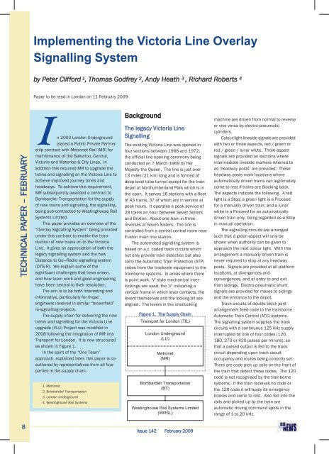
The supply chain for delivering the new<br />
trains and signalling for the Victoria Line<br />
upgrade (VLU) Project was modified in<br />
2008 following the integration of MR into<br />
Transport for London. It is now structured<br />
as shown in Figure 1.<br />
In the spirit of the “One Team”<br />
approach, explained later, this paper is coauthored<br />
by representatives from all four<br />
parties in the supply chain.<br />
1. Metronet<br />
2. Bombardier Transportation<br />
3. London Underground<br />
4. Westinghouse Rail Systems<br />
Background<br />
The legacy Victoria Line<br />
Signalling<br />
The existing Victoria Line was opened in<br />
four sections between 1968 and 1972,<br />
the official line opening ceremony being<br />
conducted on 7 March 1969 by Her<br />
Majesty the Queen. The line is just over<br />
13 miles (21 km) long and is formed of<br />
deep-level tube tunnel except for the train<br />
depot at Northumberland Park which is in<br />
the open. It serves 16 stations with a fleet<br />
of 43 trains, 37 of which are in service at<br />
peak hours. It operates a peak service of<br />
28 trains an hour between Seven Sisters<br />
and Brixton. About one train in three<br />
reverses at Seven Sisters. The line is<br />
controlled from a central control room near<br />
Euston main line station.<br />
The automated signalling system is<br />
based on a.c. coded track circuits which<br />
not only provide train detection but also<br />
carry the Automatic Train Protection (ATP)<br />
codes from the trackside equipment to the<br />
trainborne systems. In areas where there<br />
is point work, ‘V’ style mechanical interlockings<br />
are used, the ‘V’ indicating a<br />
vertical frame in which lever contacts, the<br />
levers themselves and the locking till are<br />
aligned. The levers in the interlocking<br />
Figure 1. The Supply Chain<br />
Transport for London (TfL)<br />
London Underground<br />
(LU)<br />
Metronet<br />
(MR)<br />
Bombardier Transportation<br />
(BT)<br />
Westinghouse Rail Systems Limited<br />
(WRSL)<br />
machine are driven from normal to reverse<br />
or vice versa by electro-pneumatic<br />
cylinders.<br />
Colour-light lineside signals are provided<br />
with two or three aspects, red / green or<br />
red / green / lunar white. Three-aspect<br />
signals are provided on sections where<br />
intermediate lineside markers referred to<br />
as ‘headway posts’ are provided. These<br />
headway posts mark locations where<br />
automatically driven trains can legitimately<br />
come to rest if trains are blocking back.<br />
The aspects indicate the following. A red<br />
light is a Stop; a green light is a Proceed<br />
for a manually driven train; and a lunar<br />
white is a Proceed for an automaticallydriven<br />
train only, being regarded as a Stop<br />
in manual operation.<br />
The signalling circuits are arranged<br />
such that a green aspect will only be<br />
shown when authority can be given to<br />
approach the next colour light. With this<br />
arrangement a manually driven train is<br />
never required to stop at any headway<br />
posts. Signals are provided at all platform<br />
locations, at divergences and<br />
convergences, and at entry to and exit<br />
from sidings. Electro-pneumatic shunt<br />
signals are provided for moves to sidings<br />
and the entrance to the depot.<br />
Track circuits of double block joint<br />
arrangement feed code to the trainborne<br />
Automatic Train Control (ATC) systems.<br />
The signalling system supplies the track<br />
circuits with a continuous 125 kHz supply<br />
interrupted by one of four codes (120,<br />
180, 270 or 420 pulses per minute), so<br />
that a pulsed output is fed to the track<br />
circuit depending upon track circuit<br />
occupancy and routes being correctly set.<br />
There are code pick up coils on the front of<br />
the train that detect these codes. The 120<br />
code is not recognised by the trainborne<br />
systems. If the train receives no code or<br />
the 120 code it will apply its emergency<br />
brakes and come to rest. Also fed into the<br />
rails and picked up by the train are<br />
automatic driving command spots in the<br />
range of 1 to 20 kHz.<br />
8<br />
Issue <strong>142</strong> <strong>Feb</strong>ruary 2009


