

IRSE News 142 Feb 09.pdf
IRSE News 142 Feb 09.pdf
IRSE News 142 Feb 09.pdf

You also want an ePaper? Increase the reach of your titles
YUMPU automatically turns print PDFs into web optimized ePapers that Google loves.
TECHNICAL PAPER – FEBRUARY<br />
12<br />
team. This enabled any issues with the<br />
build to be identified away from the<br />
railway, and before on-site installation<br />
commenced, thus reducing rework and<br />
access requirements.<br />
Early prototype build of the SER<br />
products also enabled flexibility to be built<br />
into the layout and cubicle designs. This<br />
was of great assistance in addressing the<br />
challenge posed by space—or rather lack<br />
of space—to install the new signalling.<br />
Whilst the Victoria Line was originally<br />
designed with additional equipment rooms<br />
for future upgrade, over time these have<br />
been used for other systems such as more<br />
advanced and sophisticated communications<br />
infrastructure. Therefore space was at a<br />
premium and maximising the flexibility of<br />
the new signalling to fit into a wide variety<br />
of differently shaped and sized rooms has<br />
proved important (see Figure 8).<br />
This prototype SER then became the<br />
core of the STE, with the addition of partial<br />
adjacent sites, the trainborne equipment<br />
and simulated external interfaces for the<br />
train. Within the factory the STE provides<br />
as much of the real system as possible, so<br />
simulation is limited to speed sensors and<br />
APR readers alone. The STE has been<br />
extended to include the communications<br />
interfaces from the train, and thus<br />
supports train integration work. The first<br />
use of the STE and other test environments<br />
was to demonstrate the connectivity,<br />
i.e. the backbone of the system<br />
concept, very early in the project. Whilst<br />
this may now seem a small step, particularly<br />
to those at the heart of the project<br />
engineering work, it provided the wider<br />
project team up through the supply chain<br />
with something tangible to focus on. In<br />
large and complex projects spread over<br />
long periods, managing the people and<br />
their expectations and giving morale or<br />
confidence boosts such as this is as<br />
important as the ‘real’ engineering. The<br />
STE has now been used to conduct formal<br />
system testing of the integrated system.<br />
Application data test tools<br />
A range of different tools have been<br />
developed to enable application data to be<br />
tested without disruptive access to the<br />
railway. In common with a number of electronic<br />
interlockings, WESTRACE has a<br />
Graphical Simulator (GSIM) that is validated<br />
to support control table and principles<br />
testing in the office environment.<br />
Correspondence and interface testing<br />
for the installed system is then carried out<br />
at each site. An analogous approach has<br />
been adopted for the DTG-R components.<br />
As with GSIM, the technology strategy is to<br />
implement the key product functionality on<br />
an office computer and then verify and<br />
validate this. For DTG-R this tool is termed<br />
Geographic Data Simulator (GDSIM). It<br />
enables functional testing of the key safety<br />
functions, e.g. authority generation against<br />
the relevant control tables and principles.<br />
This leaves the need to conduct correspondence<br />
tests between the DTG-R data<br />
and the railway.<br />
DTG-R data correspondence testing<br />
has been achieved using a development of<br />
a sophisticated track surveying tool termed<br />
KRAB. This provides very accurate<br />
measurement of distances along both<br />
running rails together with stepping<br />
through the compiled DTG-R data, to<br />
enable testers to confirm on site at the<br />
time of measurement that the data items<br />
and the railway align correctly.<br />
Off-site test track<br />
Bombardier have a test track at Derby on<br />
which the integrated rolling stock and<br />
signalling system has been extensively<br />
tested. It enables each new train to be<br />
dynamically tested under ATO and ATP<br />
operation prior to delivery to the Victoria<br />
Line. Access is close to 24 hours a day,<br />
seven days a week, which dramatically<br />
reduces elapsed time by extensive shift<br />
working for testing.<br />
The first use of the Bombardier Derby<br />
test track was with the “Configuration B<br />
Test Train,” a train of 1967 stock fitted<br />
with the new signalling system in passive<br />
mode that enables demonstration of the<br />
integrated train and trackside functionality<br />
prior to completion of Train 1, the first preseries<br />
train of the 2009 stock. As with the<br />
early integration on the STE, the Configuration<br />
B Test Train was part of a theme of<br />
early integration and test work, the aim of<br />
which was to “validate” the overall system<br />
before the detailed and very formal verification<br />
and validation of the products and<br />
system. This proved invaluable in identifying<br />
minor design flaws early in the development<br />
cycle and thus enabled faster<br />
resolution at lower cost.<br />
Power Supply<br />
630V<br />
d.c.<br />
2R<br />
R<br />
+420V<br />
+210V<br />
Inductor<br />
Inductor<br />
Running Rail / Traction Fault Conductor Network<br />
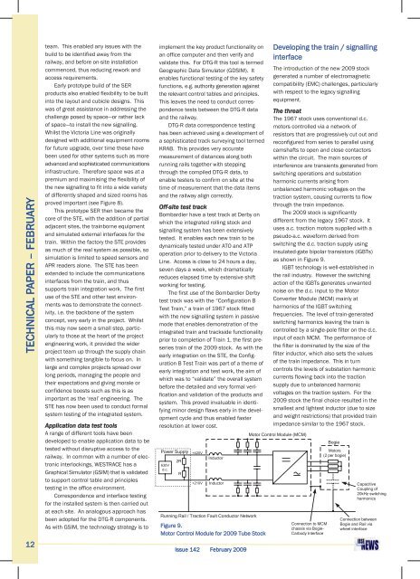
Figure 9.<br />
Motor Control Module for 2009 Tube Stock<br />
Issue <strong>142</strong> <strong>Feb</strong>ruary 2009<br />
Developing the train / signalling<br />
interface<br />
The introduction of the new 2009 stock<br />
generated a number of electromagnetic<br />
compatibility (EMC) challenges, particularly<br />
with respect to the legacy signalling<br />
equipment.<br />
The threat<br />
The 1967 stock uses conventional d.c.<br />
motors controlled via a network of<br />
resistors that are progressively cut out and<br />
reconfigured from series to parallel using<br />
camshafts to open and close contactors<br />
within the circuit. The main sources of<br />
interference are transients generated from<br />
switching operations and substation<br />
harmonic currents arising from<br />
unbalanced harmonic voltages on the<br />
traction system, causing currents to flow<br />
through the train impedance.<br />
The 2009 stock is significantly<br />
different from the legacy 1967 stock. It<br />
uses a.c. traction motors supplied with a<br />
pseudo-a.c. waveform derived from<br />
switching the d.c. traction supply using<br />
insulated-gate bipolar transistors (IGBTs)<br />
as shown in Figure 9.<br />
IGBT technology is well-established in<br />
the rail industry. However the switching<br />
action of the IGBTs generates unwanted<br />
noise on the d.c. input to the Motor<br />
Converter Module (MCM) mainly at<br />
harmonics of the IGBT switching<br />
frequencies. The level of train-generated<br />
switching harmonics leaving the train is<br />
controlled by a single-pole filter on the d.c.<br />
input of each MCM. The performance of<br />
the filter is dominated by the size of the<br />
filter inductor, which also sets the values<br />
of the train impedance. This in turn<br />
controls the levels of substation harmonic<br />
currents flowing back into the traction<br />
supply due to unbalanced harmonic<br />
voltages on the traction system. For the<br />
2009 stock the final choice resulted in the<br />
smallest and lightest inductor (due to size<br />
and weight restrictions) that provided train<br />
impedance similar to the 1967 stock.<br />
Motor Control Module (MCM)<br />
Connection to MCM<br />
chassis via Bogie-<br />
Carbody Interface<br />
Bogie<br />
Motors<br />
(2 per bogie)<br />
Capacitive<br />
Coupling of<br />
20kHz switching<br />
harmonics<br />
Connection between<br />
Bogie and Rail via<br />
wheel interface


