BPMN and Beyond Business process modelling notation, workflow ...
BPMN and Beyond Business process modelling notation, workflow ...
BPMN and Beyond Business process modelling notation, workflow ...

Create successful ePaper yourself
Turn your PDF publications into a flip-book with our unique Google optimized e-Paper software.
Extended Entity-Relationship Model<br />
Bernhard Thalheim<br />
Christian-Albrechts University Kiel, http://www.informatik.uni-kiel.de/∼thalheim<br />
SYNONYMS<br />
EERM, HERM; higher-order entity-relationship model; hierarchical entity-relationship model<br />
DEFINITION<br />
The extended entity-relationship (EER) model is a language for defining the structure (<strong>and</strong> functionality) of<br />
database or information systems. Its structure is developed inductively. Basic attributes are assigned to base data<br />
types. Complex attributes can be constructed by applying constructors such as tuple, list or set constructors to<br />
attributes that have already been constructed. Entity types conceptualise structuring of things of reality through<br />
attributes. Cluster types generalise types or combine types into singleton types. Relationship types associate<br />
types that have already been constructed into an association type. The types may be restricted by integrity<br />
constraints <strong>and</strong> by specification of identification of objects defined for a type. Typical integrity constraints of<br />
the extended entity-relationship model are participation, look-across, <strong>and</strong> general cardinality constraints. Entity,<br />
cluster, <strong>and</strong> relationship classes contain a finite set of objects defined on these types. The types of an EER schema<br />
are typically depicted by an EER diagram.<br />
HISTORICAL BACKGROUND<br />
The entity-relationship (ER) model was introduced by P.P. Chen in 1976 [1]. The model conceptualises <strong>and</strong><br />
graphically represents the structure of the relational model. It is currently used as the main conceptual model for<br />
database <strong>and</strong> information system development. Due to its extensive usage a large number of extensions to this<br />
model were proposed in the 80’s <strong>and</strong> 90’s. Cardinality constraints [1, 3, 4, 8] are the most important generalisation<br />
of relational database constraints [7]. These proposals have been evaluated, integrated or explicitly discarded in an<br />
intensive research discussion. The semantic foundations proposed in [2, 5, 8] <strong>and</strong> the various generalisations <strong>and</strong><br />
extensions of the entity-relationship model have led to the introduction of the higher-order or hierarchical entityrelationship<br />
model [8] which integrates most of the extensions <strong>and</strong> also supports conceptualisation of functionality,<br />
distribution [9], <strong>and</strong> interactivity [6] for information systems. Class diagrams of the UML st<strong>and</strong>ard are a special<br />
variant of extended entity-relationship models.<br />
The ER conferences (annually; since 1996: International Conference on Conceptual Modeling,<br />
http://www.conceptualmodeling.org/) are the main forum for conceptual models <strong>and</strong> <strong>modelling</strong>.<br />
SCIENTIFIC FUNDAMENTALS<br />
The extended entity-relationship model is mainly used as a language for conceptualisation of the structure of<br />
information systems applications. Conceptualisation of database or information systems aims to represent the<br />
logical <strong>and</strong> physical structure of an information system. It should contain all the information required by the<br />
user <strong>and</strong> required for the efficient behavior of the whole information system for all users. Conceptualisation may<br />
further target the specification of database application <strong>process</strong>es <strong>and</strong> the user interaction. Structure description<br />
are currently the main use of the extended ER model.<br />
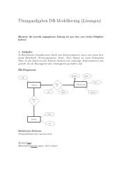
An example of an EER diagram.<br />
The EER model uses a formal language for schema definition <strong>and</strong> diagrams for graphical representation of the