REGENERATION OF GAC-F400 BY SCCO2: EFFECT OF ... - ISASF
REGENERATION OF GAC-F400 BY SCCO2: EFFECT OF ... - ISASF
REGENERATION OF GAC-F400 BY SCCO2: EFFECT OF ... - ISASF

Create successful ePaper yourself
Turn your PDF publications into a flip-book with our unique Google optimized e-Paper software.
compounds and much reduced mass transfer limitations, hence they give much higher<br />
recovery in desorption, and less environmental impact than conventional solvent regeneration.<br />
MATERIALS AND METHODS<br />
Materials: Caprolactam ((C 6 H 11 ON) is the adsorbate supplied by Sigma Chemicals UK.<br />
Granular activated carbon Filtrasorb 400 is the adsorbent, supplied by Chemviron carbon, UK<br />
Ltd. CO 2 of commercial grade is the regenerant (solvent) is supplied by BOC Ltd.<br />
Preparation of system: <strong>GAC</strong> F-400 was first crushed using a rod mill and screened to a<br />
series of particle size ranges. Each fraction was repeatedly rinsed with distilled water to<br />
remove fines, dried at 110 0 C for 24 hours and stored in airtight containers. Aqueous<br />
solutions were prepared (using distilled water) and brought into contact with 3 g of activated<br />
carbon in 1L reactors and magnetically stirred overnight. The exhausted activated carbon was<br />
then filtered out and dried at 110 0 C for 24 hours. After drying, 2.5 g of prepared exhausted<br />
carbon was packed in a 0.8 cm ID stainless steel 316 tube with a height of 14 cm. The packed<br />
bed desorber was then fitted in the Test rig.<br />
The operation rig:<br />
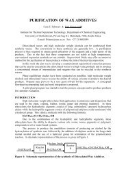
Figure 1 is a schematic diagram of the experimental set up:<br />
1.CO 2 cylinder, 4.Freezer unit, 6.Liquid pump, 11.Co-solvent injection, 13.Heat exchange coil,<br />
14.Desorber, 16.Insulated tubing, 21.Solvent reservoir, 23.Micro metering valve, 24.Heating Tape, 25.Cold<br />
trap 26.Sampling point, 27.Rotameter, 28.Filter, 29.Dry test meter, 17.Bursting disk, 3, 8, 18 Pressure<br />
gauges, 5, 9, 19 Temperature gauges, 2, 7, 10, 12, 20, 22 Stop valves.<br />
Figure 1: A schematic diagram of the operation rig.<br />
Carbon dioxide withdrawn from the cylinder was chilled then compressed to the<br />
operating pressure, before passing through a heat exchanger coil where it was heated to the<br />
operating temperature. It then passed through the desorber unit, which are immersed in<br />
constant temperature water bath, maintaining the operating temperature within ±1 0 C. The exit<br />
from the desorber was then expanded across a micro metering valve. The flow rate in the<br />
desorber was determined by the volumetric flow rate of the expanded gas as it passed through<br />
the Rota-meter and the total flow by the Dry test meter.<br />
The desorbed caprolactam was collected in a cold trap which contained Ethanol at 0<br />
0 C. Before withdrawing a 5-ml sample from the cold trap, the flow of CO 2 was temporarily<br />
stopped by the stop valve (6), and then the expansion zone was washed with 10 ml of Ethanol<br />
from the solvent reservoir.