


Create successful ePaper yourself
Turn your PDF publications into a flip-book with our unique Google optimized e-Paper software.
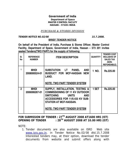
Government of India<br />
Department of Space<br />
MASTER CONTROL FACILITY<br />
HASSAN – 573201 INDIA<br />
PURCHASE & STORES DIVISION<br />
TENDER NOTICE NO.02/08 15.7.2008.<br />
BRIEF TENDER NOTICE<br />
On behalf of the President of India, Purchase & Stores Officer, Master Control<br />
Facility, Department of Space, Government of India, Hassan – 573 201 invites<br />
sealed Tenders(TWO PART) for the supply of following:<br />
Sl.<br />
No<br />
REFERENCE<br />
NUMBER<br />
ITEM DESCRIPTION<br />
QUANTITY<br />
TENDER COST<br />
INCLUSIVE OF<br />
SALES TAX<br />
(NON-<br />
REFUNDABLE)<br />
1 MHDI<br />
2008000524-01<br />
2 MHDI<br />
2006006267-01<br />
SUBSTATION LT PANEL AND<br />
BUSDUCT FOR MCF-HASSAN NEW<br />
LAND.<br />
NOTE: TWO PART TENDER SYSTEM<br />
SUPPLY, INSTALLATION, TESTING &<br />
COMMISSIONING OF 11 KV OUTDOOR<br />
SWITCHING UNITS AND<br />
ACCESSORIES FOR 11/0.433 KV SUB-<br />
STATION AT MCF-HASSAN.<br />
NOTE: TWO PART TENDER SYSTEM<br />
1 NO. Rs.225.00<br />
1 SET Rs.225.00<br />
FOR SUBMISSION OF TENDER : 27 TH AUGUST 2008 AT1600 HRS (IST)<br />
OPENING OF TENDER : 28 TH AUGUST 2008 AT 10.00 HRS (IST)<br />
NOTE:<br />
1. Tender documents are also available on <strong>ISRO</strong> Web site<br />
www.isro.gov.in. in Tender Notice No.02/08 dtd.15.7.2008<br />
Interested tenders may, at their option, download the tender<br />
documents from website and submit offers along with
prescribed tender cost (in form of Demand Draft) as per details<br />
in the tender notification.<br />
2. Tender fee shall be acceptable only in the form of demand draft<br />
drawn in favour of Accounts Officer, Master Control Facility,<br />
payable at Hassan. No other mode of payment for tender fee is<br />
acceptable.<br />
: 2 :<br />
3. Vendors/firms name and tender number shall be indicated on<br />
the reverse side of the Demand Draft.<br />
4. While requesting for tender documents, please do not<br />
superscribe tender number and due date on the envelop.<br />
Instead indicate “Request for Tender Documents”.<br />
5. Demand Draft should not be dated prior to the date of<br />
advertisement/intimation/website (separate requests and<br />
demand draft shall be sent for each tender document).<br />
6. MCF will not be responsible for non-receipt of tender<br />
documents/offers due to postal/delay/loss in transit.<br />
7. Quotations received without payment of tender fee will be<br />
treated as unsolicited.<br />
8. Detailed specification, terms and conditions are furnished in the<br />
tender documents<br />
10.The offer should be valid for a period of Ninety days from the<br />
date of opening.<br />
11.Quotations received after the due date and time will not be<br />
considered.<br />
12.While submitting your offer, please superscribe tender number<br />
and due date on the envelope, addressed to Purchase & Stores<br />
Officer (P), Master Control Facility, Government of India,<br />
Department of Space, Hassan- 573201.<br />
13.If tender opening date happens to be public holiday tender will<br />
be opened on the next working day.<br />
14.Request for the extension of the due date will not be<br />
considered.<br />
15.Purchase & Stores Officer, MCF reserves the right to accept or<br />
reject any tenders in part or full without assigning any reasons<br />
thereof.<br />
16.Those who do not utilize the website shown at clause 01 above<br />
can buy the Tender documents from Purchase & Stores Officer,
Master Control Facility, Department of Space, Hassan-573 201,<br />
on payment of Non-refundable tender fee as indicated above,<br />
on all working days.<br />
PURCHASE & STORES OFFICER
Instructions<br />
Scope of work<br />
Master Control Facility – Hassan<br />
SUBSTATION LT PANEL & BUSDUCT FOR MCF - HASSAN NEW LAND<br />
General requirements<br />
Make<br />
Calibration<br />
Technical specifications<br />
Design standards<br />
complies to<br />
: The offer shall be submitted in two parts.<br />
-Techno-commercial with Un-priced bid.<br />
-Financial offer as per enclosed format.<br />
: GA drawing of the LT panel to be furnished with super imposed SLD and<br />
busbar configuration or proposed dimension of the panel to be furnished.<br />
: Make for all the items in BOM shall be furnished.<br />
: Deviation if any, to be mentioned clearly w.r.t switchgears, mechanical &<br />
electrical specification.<br />
: Each page of the tender document to be signed with seal.<br />
: 10 years of experience in executing similar panels.<br />
: ISO 9001 certified<br />
: CPRI type test certificate for the 50-kA short circuit test shall be<br />
enclosed for panel and bus-duct.<br />
: The offer will not be considered if the submittals are not as per the<br />
above instructions.<br />
: Design, manufacture, testing, supply, installation & commissioning of the<br />
substation LT panel including bus ducts indoor & outdoor as per the SLD<br />
considering applicable mechanical & electrical safety standards.<br />
: Panel fabrication and integration of switchgears shall be as per the<br />
approved General Assembly drawing.<br />
: Routine test of the panels at works prior to dispatch as per IS.<br />
: Input & output power cables termination is not in the scope of the supplier.<br />
: Integration of LT panel sections & interfacing control cables & accessories<br />
at site & functional testing is in the scope of the supplier.<br />
: Any one make of switchgear among the specified in bill of material only to<br />
be selected and used in the panel.<br />
: Make of switchgear should be same, i.e., make of SDFUs of all ratings<br />
should be same and make of ACBs of all ratings should be same, similarly<br />
for other items.<br />
: Any left out or additional requirements of switchgears, spares and control<br />
accessories shall be included.<br />
: Protective devices, Relays & Current Transformers calibration to be carried<br />
out by NABL accredited party other than manufacturer.<br />
: National Electrical Code (NEC-NFPA 70)<br />
: National Electrical Manufacturers Association (NEMA)<br />
: National Fire Protection Association (NFPA 75) and latest IE rules.<br />
Electrical requirements<br />
Rating<br />
: 2.0 MVA, Bus bar continuous current carrying capacity shall be 120% of<br />
the rated 2.0 MVA at 380 VAC.<br />
Input<br />
: 380 to 440VAC at 50 Hz, 3-phase, four-wire-plus-ground.<br />
Output<br />
: 240 / 415 VAC 3-phase, four-wire-plus-ground, wye configuration.<br />
Operating PF : From 0.5 lead to 0.5 lagging.<br />
Short time rating : Short time withstand current 50 kA RMS for 1 sec.<br />
Semi Modular substation LT panel –Specification 1
Master Control Facility – Hassan<br />
Environmental requirements<br />
: Storage temperature range shall be 0° to + 85°C<br />
: Operating temperature range shall be 0° to 50°C<br />
: Operation shall be reliable in an environment with 0% to 95% noncondensing<br />
RH.<br />
Fabrication<br />
Panel design<br />
: Semi-modular design concept shall be adopted for panel fabrication.<br />
: Free standing, floor mounting and suitable for indoor installation.<br />
: Profile should have holes of standard size punched at standard pitch<br />
throughout the length.<br />
: The L / U / square tubular frame shall be assembled with die casted<br />
corners / tripods or baying clamp for three-dimensional flexibility in design<br />
configuration.<br />
: Mounting plate’s -Mild steel, 2 mm, epoxy polyester powder coated.<br />
: Fixtures for mounting switchgears shall provide flexibility for adjustments in<br />
X, Y & Z-axis.<br />
: The panel shall have easily removable and interchangeable sections.<br />
: Horizontal busbars are to be located at the top of the panel.<br />
: Stainless steel high tensile strength fasteners shall be used for panel.<br />
: Stainless steel fasteners set of high tensile strength (consisting of<br />
hexagonal bolt –1 no, flat washers –2 nos, spring washers –1 no and<br />
hexagonal nut –1 no) shall be provided for each termination point.<br />
: The length of the hexagonal bolt shall be adequate for insertion of 3 lugs of<br />
requisite rating.<br />
: Required service clearances shall be provided to carry out preventive and<br />
remedial maintenance from front and rear side.<br />
: The panel shall be naturally convection-cooled & shall allow continuous<br />
full-load operation, maintaining the temperatures within tolerance level of<br />
components.<br />
: Each bus bar compartment should have a barrier with 1.6 mm thick<br />
galvanized coated & painted with fire resistance paint.<br />
: Proper fixing arrangement shall be made for mounting metering &<br />
protection current transformers.<br />
: The degree of protection for the panel shall be IP 31<br />
Panel dimension<br />
Width<br />
: As per design requirement.<br />
Depth<br />
: Shall not be more than 1200 mm<br />
Height<br />
: Shall not be more than 2400 mm (including plinth)<br />
Plinth<br />
: Shall be 100 / 50 mm height<br />
Ground clearance : Minimum ground clearance for switchgear mounting shall be 350 mm<br />
including plinth.<br />
Weight / Sq. mm : Distributed floor weight shall be less than 1225 kg sq. m.<br />
Switchgears<br />
operation<br />
Plinth<br />
: Switchgears are to be mounted in such a way its handle operation shall<br />
confirm to per IS 4237<br />
-ON Closing –Clockwise i.e., Vertically upward<br />
-OFF Opening –Anti-clockwise i.e., Vertically down ward<br />
: The panel shall be supplied along with base plinth of 100 / 50 –mm height<br />
for each transportable modular section and shall be made of C – channel<br />
forming sectional ‘Box’.<br />
Semi Modular substation LT panel –Specification 2
Master Control Facility – Hassan<br />
Door<br />
Cable<br />
compartment<br />
Bus duct<br />
: Doors shall be with concealed hinges and flush type locks.<br />
: Doors that are bolted for busbar chambers should be flush in design such<br />
that the bolt head and the door surface are in one level.<br />
: Doors shall be of 2 mm thick CRCA sheet.<br />
: High quality door gasket should be used for dust and vermin proof.<br />
: Each bolt shall have plastic washers on the inner side of the door such that<br />
the bolt will remain with the door on removal of the door.<br />
: The switch handle shall be interlocked such that the door of enclosure<br />
cannot be opened unless the switch is in OFF position, however,<br />
mechanical interlock defeat mechanism has to be provided.<br />
: All rear doors shall be of hinged type with locking arrangement at three<br />
places (top, middle and bottom).<br />
: All horizontal and vertical bus bars chamber covers shall be of bolted type.<br />
: Hinged doors shall be provided for all switchgear compartments.<br />
: Stiffeners are to be provided for all rear doors for mechanical strength.<br />
: Cable entry gland plates shall be provided at the bottom.<br />
: Each gland plate shall be chrome plated with 3mm thickness & adequately<br />
supported.<br />
: Independent, detachable gland plates for each cable considering 2 cables /<br />
outlet shall be provided at the cable compartments & terminal chamber.<br />
: Liberal space shall be provided in the cable compartment as well as switch<br />
compartment to facilitate termination of cables.<br />
: Provision shall be made for proper clamping of the cables above the<br />
glands and cable clamps to avoid weight of cables acting directly on the<br />
termination.<br />
: Wide cable alley shall be provided for easy bending and termination of<br />
cables. (Bending radii =R>=12 x overall diameter of cables)<br />
: Non-segregated, bus ducts having 3 phase & neutral bus bars housed in<br />
common galvanized zinc sheet metallic enclosure.<br />
: Degree of protection for the bus duct shall be IP 54, outdoor bus duct<br />
section shall be of double roof type. The top cover should be of rain<br />
canopy type.<br />
: Busbar material –High-purity electrolyte Aluminium confirming to latest<br />
IS standard.<br />
: Bus duct rating shall be 2000A at 415 VAC, 50 Hz.<br />
: Short circuit withstand capacity –50 kA (rms) for 1 sec, Confirming to IEC<br />
IS-8623-2.<br />
: Insulation material –PVC sleeved of suitable class & insulation.<br />
: Neutral bus bar rating shall be 50% of the phase cross section.<br />
: Earth busbar of tinned copper size 35 x 4 mm shall be fitted outside the<br />
duct on either side through out the length.<br />
: Bus duct enclosure shall be fabricated with CRCA electro galvanized,<br />
1.8-mm thick sheet with epoxy polyester powder coating, inner surface to<br />
be painted with flame proof fire retardant paint.<br />
: Transformer terminal to be connected with flexible joints to the palm<br />
connector through bi-metal shim.<br />
: All supporting structure materials shall be of GI (hot dip).<br />
: Standard accessories to be used as per the system requirement like,<br />
expansion joint at every bends, phase cross over, rubber bellow,<br />
marshalling cabinet, adopter at transformer and panel end & wall frame.<br />
: The total requirement of indoor & outdoor bus duct length will be provided<br />
at the time of approval of GA drawing.<br />
Semi Modular substation LT panel –Specification 3
Painting<br />
Surface treatment<br />
Type<br />
External Finish<br />
Internal Finish<br />
Master Control Facility – Hassan<br />
: Triple surface treatment<br />
Phosphating, Electrophoretic dipcoat-priming and Powder coating<br />
: Epoxy polyester powder coated<br />
: Mat or Gloss<br />
: Flame proof Fire retardant paint<br />
Color : Outer surface of the panel –Siemens gray. (color code IS: 952)<br />
: Plinth –Black<br />
: Inner surface of the panel –Fire resistance paint.<br />
: Bus duct – Siemens gray (color code IS: 952)<br />
Busbar System<br />
Material<br />
: High-purity electrolyte Aluminium complying to IS 5082-1981, 63401-WP<br />
Confirming to : DIN 1759, DIN 40 500 and relevant bus bar IS standard<br />
Ele. Conductivity : 100% as per IAC Standard<br />
Main busbar rating : 120 % of 2.0 MVA, continuous current rating<br />
Distribution busbar : 120 % of the switchgear rating connected<br />
N –busbar rating : 50% of the phase busbar rating<br />
Busbar system : TPN-E<br />
Busbar<br />
arrangement<br />
Phase sequence<br />
Normal service<br />
condition<br />
: If the number of busbars per phase exceeds more than three, then<br />
interleaved system shall be adopted. The phase sequence will be N-R1-<br />
Y1-B1-R2-Y2-B2 to minimize skin, proximity, power loss and temperature rise.<br />
: The phase sequence of buabars arrangement shall be N-R-Y-B from rear to front.<br />
: Should not raise 40 0 C above ambient temperature as per IS 4237<br />
(Considering Max ambient air temp. not exceeding 40 0 C at an altitude 992 MSL)<br />
Auxiliary Busbar System<br />
Material<br />
: High-purity electrolyte Aluminium complying to IS 5082 -1981, 63401-WP<br />
Size<br />
: As per design requirement.<br />
Control power : 24 VDC & 230 VAC<br />
Location<br />
: Top front or rear top front chamber of the panel.<br />
Supports / tap-off : Integrated busbar supports and tap-off system shall be adopted.<br />
Safety<br />
: Auxiliary busbars shall be insulated & sleeved.<br />
Bus bars supporting insulators<br />
Material<br />
: Self-extinguishing moulded Fiberglass reinforced thermosetting plastic or<br />
equivalent.<br />
Properties : Higher mechanical strength, High dielectric strength<br />
: High temperature with stand capability, Non flammable<br />
: Non hygroscopic & Ribbed construction to prevent tracking<br />
Supporting : Individual supports for each phase shall be used to eliminate risk of<br />
tracking between phases.<br />
Busbars protection<br />
Separate chamber : Horizontal and vertical busbar should be enclosed in a separate chamber.<br />
Sleeving<br />
: Horizontal busbars, vertical busbars, switchgear input busbars and<br />
switchgears output busbar are to be totally sleeved with color coded heat<br />
shrunk PVC to protect against accidental contact and tracking caused by<br />
dust, humidity and vermin.<br />
Semi Modular substation LT panel –Specification 4
Shrouds<br />
Cabling<br />
Separate chamber<br />
Safety interlock<br />
Doors<br />
Wiring<br />
Specification<br />
Confirming to : IS: 694 / 1990<br />
Size & Rating<br />
Connectors<br />
Cage clamps<br />
Ferruling<br />
Meters & Relays<br />
Communication<br />
devices<br />
Master Control Facility – Hassan<br />
: All joints on horizontal busbars shall be provided with shrouds or insulated<br />
to provide a completely insulated system.<br />
: The cabling chamber for the panel shall be at the rear side of the panel.<br />
: It should be separated from the busbar zone and switchgear compartment.<br />
: The control cables and terminals are to be mounted in a separate<br />
compartment. (Below ACB compartment / away from power cables).<br />
: The door cannot be opened unless the breaker is in ‘Isolated position’.<br />
: The door cannot be opened unless MCCB / SDFU is in OFF position.<br />
: Defeat facility shall be provided to facilitate testing / inspection for all<br />
switchgears.<br />
: HFFR unilay, pre twisted single core multi strand electrolyte grade,<br />
annealed copper cable,<br />
: 1.5 sq-mm, 1.1 Kv grade shall be used for all control / interlock wiring.<br />
: 2.5 sq-mm, 1.1 Kv grade shall be used for all CT related wiring.<br />
: Power cable of suitable size for SDFUs / MCBs of rating up to 63 A.<br />
: Color of the cable shall be Gray for control wiring.<br />
: Mating type male-female connectors and holders shall be used between<br />
each transportable section for control wiring.<br />
: Din rail mounting, cage clamp terminal connectors shall be used for all<br />
control and power wiring up to 63A.<br />
: Standard ferruling concept shall be followed for clear identification of<br />
control circuit wiring as per IS 375 mentioned below.<br />
-Letter ‘A’ – CT for primary protection excluding O/C<br />
-Letter ‘B’ –CT for busbar protection<br />
-Letter ‘C’ –CT for O/C including E/F & instantaneous<br />
-Letter ‘D’ –CT for metering & voltage control.<br />
-Letter ‘E’ –Reference voltage for instrument metering & protection<br />
-Letter ‘F’ – Reference voltage for voltage control<br />
-Letter ‘G’ – Reference voltage for synchronizing<br />
-Letter ‘H’ –AC & AC/DC supplies Numbers –1 to 69 for S’gears & Gen.<br />
-Letter ‘J’ – DC supply<br />
-70 to 99 for Transformers<br />
-Letter ‘K’ – Closing & tripping control circuit – Any no. 1 upward<br />
-Letter ‘L’ – Alarm & indication – Any no. 1 upward<br />
-Letter ‘M’ – Auxiliary & motor control devices –1 to 19 for Switchgears, 20<br />
to 69 for Generators & 70 to 99 for Transformers<br />
-Numbers 10 to 29 – R phase<br />
-Numbers 30 to 49 – Y phase<br />
-Numbers 50 to 69 – B phase<br />
-Numbers 70 to 89 – Residual & Neutral CT &<br />
-Numbers 90 –Earth wire directly connected to earth bar.<br />
: For DC bus -Positive –Red, -Negative –Blue<br />
: Auxiliary power supply shall be taken independently through MCBs from<br />
auxiliary busbars.<br />
: Communication points of all communicable devices (viz., ACB releases,<br />
digital TVM & protective relays) shall be wired with twisted pair cable to<br />
the common compartment.<br />
Semi Modular substation LT panel –Specification 5
Trip circuit<br />
Indicating lamps<br />
CTs wiring<br />
MCBs input power<br />
Master Control Facility – Hassan<br />
: ACBs / MCCBs shunt trip power supply shall be taken independently<br />
through MCBs from auxiliary busbars.<br />
: Wiring for presence of input power, ACBs / MCCBs ON / OFF and fault trip<br />
status indication.<br />
: Isolators for digital TVM & shorting links for analog meters shall be used.<br />
: Multiple MCB’s input power supply should be tapped through 125A SDFU<br />
for short circuit protection.<br />
Name plates / stickers<br />
Name plate : Nameplates for Transformers & Generators incomers and each outgoing<br />
feeder outlets shall be provided.<br />
: Each nameplate shall contain feeder no, switchgear rating and<br />
nomenclature.<br />
: Nameplates size, design, and color combination and nomenclature for<br />
each output feeder will be furnished during approval of drawing.<br />
: The approved SLD of the panel shall be screen-printed / computerized<br />
print over an A3 size 2 mm thick aluminum sheet or foam board. It shall be<br />
fixed at top-center of the panel.<br />
Laminated stickers : Laminated stickers of suitable size with good quality adhesive shall be<br />
fixed at each terminal blocks, meters, relays on the inner side for clear<br />
Panel specification<br />
plate<br />
Grounding / Earthing<br />
Type<br />
Panel earth bus<br />
Switchgear<br />
Panel doors<br />
Meters / relays<br />
Inspection / Testing<br />
First stage<br />
inspection<br />
Final inspection &<br />
testing<br />
identification.<br />
: The panel shall have the specification plate as per the IS reference<br />
standard 2675<br />
-Rated voltage AC or DC Hz<br />
-Total number of outgoing ways / feeders<br />
-Rated current of each outgoing feeders<br />
-Number of poles<br />
-Manufacturer name / Trade mark / Address<br />
-Customer PO reference and date<br />
-Year of manufacturing<br />
: Two-point ground in accordance with the recommendations of IEEE<br />
Standard and the requirements of the NEC.<br />
: High-purity electrolyte copper E-Cu 57 busbar of size 50x6 mm should be<br />
run all along the width of the panel at front or rear bottom surface.<br />
: All ACBs and switchgears body shall be earthed by 25x3 mm copper strip.<br />
: Doors shall be earthed, if electrical equipment (meters / relays / lamps)<br />
mounted by a yellow green 2.5 Sq. mm wire lugged at both ends.<br />
: All meters / relays shall be earthed to the profile by a yellow green 2.5 Sq.<br />
mm wire lugged at both ends.<br />
: Mechanical -structural fabrication after approval of GA drawing.<br />
: Verification of components as per PO bill of material.<br />
: Minor modifications in mechanical / electrical changes pointed out by MCF<br />
inspecting officer shall be carried out, if necessary, without additional cost.<br />
: After integration of switchgears and wiring.<br />
: Inspection and testing as per checklist.<br />
: Calibrated testing & measuring instruments are to be used for routine test.<br />
: Any deviations from the specifications or in testing shall be attended &<br />
offered for re-inspection.<br />
Semi Modular substation LT panel –Specification 6
Documentation<br />
Comprising<br />
Warranty<br />
Master Control Facility – Hassan<br />
: Party to submit the PDR document for approval with in 45 days after<br />
receiving the <strong>purchase</strong> order.<br />
: PDR document shall contain –SLD, GA drawing with superimposed busbar<br />
configuration, Structural details of panel / bus duct, Make and Catalogue<br />
number of switchgears & accessories, Control circuit drawing and Delivery<br />
schedule.<br />
: As built GA, SLD, Control drawing & busbar layout configuration in A3 size.<br />
: Meters / Protective Relays operating manuals.<br />
: Meters / protective Relays test and Calibration certificates.<br />
: Metering / Protection CT calibration certificates<br />
: Bill of actual material used with make, cat no and quantity.<br />
: Routine / Acceptance test results as per standard.<br />
: Specific instructions for installation and operation / maintenance<br />
procedures.<br />
: Document shall be supplied in duplicate with hardbound cover having<br />
printed title.<br />
: The entire document is to be copied & supplied in CD.<br />
: Against defects in material and workmanship<br />
: 12 months from the date of commissioning or<br />
: 18 months from the date of supply and acceptance which ever is earlier.<br />
Functional requirements<br />
Inter lock<br />
: Electrical & Mechanical interlock between T1 & T2 shall be provided.<br />
: The bus couplers BC1 & BC2 shall not close if there is power on either<br />
side of the bus.<br />
: The bus couplers BC3 & BC4 shall close if the DG systems are running in<br />
synchronizing mode.<br />
: The bus couplers BC3 & BC4 shall not close if the DG systems are<br />
running in solo mode of operation.<br />
: The differential trip potential free contact shall be made available to trip the<br />
diesel engine also.<br />
: The detailed interlock / operational scheme in auto / manual mode of<br />
operation will be provided during PDR<br />
ACBs<br />
: Shall be received from the manufacturer with all its accessories in pre<br />
wired condition as per the bill of material.<br />
: Incoming & outgoing busbar termination orientation should be ordered as<br />
per the panel requirement.<br />
Bus coupler (BC2)<br />
Interposing relays<br />
Auxiliary contacts<br />
: Bus coupler BC2 section shall be kept with a gap of 750 mm on either side<br />
to have separation from utility & captive sources.<br />
: Control power supply to interposing relays (24 VDC) shall be taken through<br />
modular fuse holder with HRC fuse links.<br />
: Transformer and Generator side change over contacts wiring shall be<br />
terminated separately in mains and generator side compartments.<br />
: Change over contacts, aux. contacts wiring of Transformers, Generators &<br />
Bus couplers shall be terminated to separate terminal blocks with TB no<br />
for clear identification.<br />
: Each terminal connector to be numbered and their input & output details to<br />
be provided.<br />
: All auxiliary contacts of ACBs, Relays, MCCBs and CT outputs shall be<br />
brought to cage clamps / mating type male-female connectors.<br />
Semi Modular substation LT panel –Specification 7
Master Control Facility – Hassan<br />
Phase sequence<br />
indicator<br />
DG auxiliary<br />
system<br />
Emergency Power<br />
OFF (EPO)<br />
Modes of<br />
operation<br />
Neutral contactor<br />
: PSI shall be provided with spring return type ON / OFF selector switch.<br />
: All DG auxiliary motor control circuits are to be placed under respective<br />
DG incoming air circuit breaker compartments.<br />
: EPO switch shall shut down the unit by activating the shunt trip of the<br />
ACBs in local & remote operation.<br />
: Manual operation<br />
: Solo operation and<br />
: Automatic operation<br />
: Solo mode operation<br />
− DG neutral Contactor to close automatically before closing of respective<br />
DG breaker.<br />
− Neutral Contactor to trip after tripping of respective DG’s.<br />
− Selector switch for enabling / disabling the neutral contactor shall be<br />
provided.<br />
: Parallel operation<br />
-Only master DG neutral contactor should be ON.<br />
-Master DG neutral tripping shall trip all DG circuit breakers.<br />
Semi Modular substation LT panel –Specification 8
Master Control Facility – Hassan<br />
Sn Description Make Qty<br />
A Switchgears & Control accessories<br />
1<br />
Air Circuit Breakers -ACB<br />
Rated operational voltage -415V 50Hz AC, 3 Pole, Electrical Draw Out type,<br />
Type of closing: Stored energy (Motor operated), Motor voltage: 240 VAC,<br />
Closing electromagnet: 240 VAC, Wiring scheme: 3Ph, 4 wire, Auto reset,<br />
Door interlock, Castle lock with key, Rated insulation voltage: 690 VAC,<br />
Utilization category -B. Ultimate breaking capacity (Icu) at 415V, 50Hz –65<br />
kA rms, Service breaking capacity (Ics) at 415V, 50Hz -65 kA, Short time<br />
withstand capacity (Icw) for 1 second: 65 kA rms, Making capacity (Icm) at<br />
415V, 50Hz -143 kA peak,<br />
Microcontroller based, true RMS sensing protection and control release<br />
capable of offering OL, SC and EF protection with variable current and time<br />
delay settings, selectable I 2 t based curves for short time and earth fault<br />
zones, self powered with % loading / LCD display. Confirming to IS 13947<br />
(Part 2) / IEC 60947-2<br />
Accessories: Auxiliary contacts: 6NO+6NC / 4 NO+4NC, Safety shutters /<br />
Inter phase barriers, Shunt release: 24 VDC, UV release: 240 VAC,<br />
Operation counter, Mechanical interlock kit, Terminal orientation / adopters -<br />
As per<br />
requirement.<br />
Make: L&T U-Power / Schneider MG-Masterpact / Siemens, Sentron-WL<br />
1a Rated Current: 800 A for Generator 3<br />
1b Rated Current: 1600 A for Transformer 2<br />
2<br />
Air Circuit Breakers -ACB (For bus couplers BC1 to BC4)<br />
Rated operational voltage -415V 50Hz AC, 3 Poles, Electrical Draw Out type,<br />
Type of closing: Stored energy type (Motor operated), Motor voltage: 240 VAC,<br />
Closing electromagnet: 240 VAC, Wiring scheme: 3Ph, 4 wire, Auto reset, Door<br />
interlock, Castle lock with key, Rated insulation voltage: 690 VAC, Utilization<br />
category -B<br />
Ultimate breaking capacity (Icu) at 415V, 50Hz –65 kA rms, Service breaking<br />
capacity (Ics) at 415V, 50Hz -65 kA, Short time withstand capacity (Icw) for 1<br />
second: 65 kA rms, Making capacity (Icm) at 415V, 50Hz -143 kA peak.<br />
Confirming to IS 13947 (Part 2) / IEC 60947-2.<br />
Accessories: Auxiliary contacts: 4NO+4NC, Safety shutters / Inter phase barriers,<br />
Shunt release: 24 VDC, UV release: 240 VAC, Operation counter, Terminal<br />
orientation / adopters: As per requirement<br />
Make: Make: L&T U-Power / Schneider MG-Masterpact / Siemens, Sentron-WL<br />
2a Rated Current: 1600 A 2<br />
2b Rated Current: 2500 A 1<br />
2c Rated Current: 3200 A 1<br />
Semi Modular substation LT panel –Specification 9
Master Control Facility – Hassan<br />
3<br />
Microcontroller based UV & OV Relays (For T1 & T2)<br />
Voltage Vn -110/240/415V settable at site, 50 Hz +/- 2.5 Hz, Auxiliary power<br />
supply: 24-110V AC/DC, Settings -Fault Voltage Vs -OV mode: 105-180% of<br />
Vn in steps of 5%, UV mode: 95-20% of Vn in steps of 5%, High Set Vhs -OV<br />
mode 110-180% of Vn in steps of 10%, -UV mode: 90-20% of Vn in steps of<br />
10%, Trip Time Characteristics -Normal Inverse NI -3.5 Sec in OV mode &<br />
5.7 in UV mode, Defnite Time -01, 10 and 100 Secs, Accuracy -+/- 5% of Vn,<br />
Auxiliary Contacts - 2 Pairs of self reset C/O contacts, Mounting -Panel<br />
mounting (Flush) type, Relay operation should not be affected by stray<br />
magnetic field. Make: L&T Model MV12A or equivalent in Siemens / Areva<br />
T&D / ASEA Brown Boveri<br />
4<br />
4<br />
Protection Relay (For T1 & T2)<br />
3Ph OC+EF+highset, Communication and breaker control with RS 485, Micro<br />
Controller based, LS OC (20-200% step 5%) HS O/C (0.2-40) in step of 0.2 In<br />
or disable & LS EF (5-80% step 5%), HS EF (0.1 to 20) on step of 0.1 On or<br />
disable, HS delay (0.1 to 2 Sec) step 0.01 sec or instantaneous, Draw out<br />
type, Auto doubling of HS, relay co-ordination, self testing & display of<br />
parameters, Site selectable trip time characteristics (NI, VI, EI & Definite<br />
Time), TMS 0.1-1.6 step 0.05, Auxiliary contacts 2NO+2NC, Auxiliary supply:<br />
24-110V AC/DC, CT Rating: 5A. Make: L&T Model MC61C or equivalent in<br />
Siemens / Areva T&D / ASEA Brown Boveri<br />
2<br />
5<br />
Digital Meter (For T1, T2, G1, G2 & G3)<br />
True RMS measuring meter to read L-L/L-N voltage, Current per phase /<br />
neutral current, Frequency, Phase rotation / Vmax. and current demand per<br />
phase, Vmin. per phase, %age of load circular bar graph. Capable of<br />
measuring power parameters viz., kW & kWh, kVA & kVAh, kVAr & kVARh,<br />
import & export etc., The meter shall be capable of reading the voltage as<br />
well as current (THD) Harmonic, Three phase at once, bright LED display.<br />
Communication port –RS 485 and Industrial standard communication<br />
protocol – MODBUS, Auxiliary power supply: 24 VDC. Make: Satec<br />
PM130EH<br />
5<br />
6<br />
7<br />
Differential Protection Relay (For G1, G2 & G3)<br />
Device code: 87, 50/51, 50LBB, 64S / 87N, Design: Numeric, Functions:<br />
Generator differential, bias % with dual adjustable slope, OC, stator EF & CB<br />
failure protection, Features: 1A or 5A site selectable, display of parameters,<br />
waveform capture feature, built in supervision & RS485 port, 4 C/O, S/R or<br />
H/R or time delay 1 C/O for self supervision, Flush mounting draw out type,<br />
Auxiliary supply 24-110V AC/DC. Make: L&T Model MD32G or equivalent in<br />
Siemens / Areva T&D / ASEA Brown Boveri<br />
Switch Disconnector Fuse Units (SDFU)<br />
Triple Pole with isolable Neutral (TPN), 415V, 50 Hz, Panel mounting type<br />
interrior version with operating mechanism and handle without HRC fuse<br />
links. Confirming to IS 13947 (Part 3), Accessories: Terminal shrouds, Fuse<br />
shrouds, Fuse barriers<br />
Make: L&T F-Line FNX series / Schneider MG Fupact SDF / Siemens -<br />
Sentron Superswitch<br />
3<br />
7a Rating: 630 Amps 15<br />
Semi Modular substation LT panel –Specification 10
Master Control Facility – Hassan<br />
7b Rating: 400 Amps 5<br />
7c Rating: 250 Amps 6<br />
8<br />
DIN TYPE HRC Fuse Links (For 7a, 7b & 7c)<br />
Rated Voltage: 415V, 50 Hz, DIN fuse Type -HN, Confirming to IS 13703,<br />
Low let through energy, High breaking Capacity of 100 kA at 415V with blown<br />
indication. Make shall be of SDFU selected or recommended by the SDFU<br />
manufacturer.<br />
8a Suitable for 630A SDFU, Rating: 500A 45<br />
8b Suitable for 400A SDFU, Rating: 315A 15<br />
8c Suitable for 250A SDFU, Rating: 200A 18<br />
9<br />
Ammeter (For all outgoing feeders)<br />
Type: Moving Iron, AC application, Size: 96x96, Flush mounting, Uniform<br />
scale <strong>division</strong>, Accuracy class 1%, CT operated 5A. Make: L&T Rishab / AE /<br />
MECO / Nippon / Havells<br />
9a Range: 0 - 600 A 15<br />
9b Range: 0 - 400 A 5<br />
9c Range: 0 - 250 A 6<br />
10<br />
Ammeter Selector switches (For LT panel)<br />
Cam operated, No of poles: 1 pole with 3 CT with OFF, Current rating -10 A,<br />
Operating angle -90 0 , panel mounting type, R-Y-B-OFF and AMMETER<br />
engraved front plate, Front plate size -60 mm, 4 hole front panel mounting.<br />
Make: L&T-Salzer / Kaycee / Schneider / Siemens<br />
26<br />
11<br />
Phase Sequence Indicator (For T1 & T2)<br />
Rotating disc type electro mechanical, Operating voltage: 50-500V, Operating<br />
frequency: 25-60 Hz, Size: 96x96 mm, Flush mounting. Make: L&T Rishab /<br />
AE / MECO / Nippon / Havells<br />
2<br />
12<br />
Current Transformers -Metering<br />
Rated secondary current -5A, Accuracy class -1%, Rated frequency -50Hz,<br />
Type - Resin cast, Shape -Circular / Rectangular with mounting accessories,<br />
Rated insulation level of CT -3 kV rms, Confirming to IS 2705. Make: L&T /<br />
Rishab / Schneider / Kappa / Kalpa / AE<br />
12a Rated primary current 1600 A, Rated burden -5 VA (For T1 & T2) 6<br />
12b Rated primary current 800 A, Rated burden -5 VA (For G1 & G2) 9<br />
12c Rated primary current 600 A, Rated burden -5 VA 45<br />
12d Rated primary current 400 A, Rated burden -5 VA 15<br />
12e Rated primary current 250 A, Rated burden -5 VA 18<br />
13<br />
Current Transformer -Protection (for T1 & T2)<br />
Rated primary current 1600A, Rated secondary current -5A, Rated burden -<br />
10VA, Accuracy -5P10, Rated frequency -50Hz, Type -Resin cast, Circular /<br />
Rectangular with fixing accessories, Rated insulation level of CT -3 kV rms,<br />
Confirming to IS 2705. Make: L&T / Rishab / Schneider / Kappa / Kalpa / AE<br />
6<br />
14<br />
Miniature Circuit Breakers (For AC control circuits)<br />
Single pole, Rating 4A, Breaking capacity 10A, confirming to IS 8828 -1996,<br />
Type 'B' tripping characteristic. Make: L&T -Hager / Siemens / Schneider /<br />
MDS -Legrand / GE having ISI mark<br />
As<br />
required<br />
Semi Modular substation LT panel –Specification 11
Master Control Facility – Hassan<br />
15<br />
16<br />
17<br />
18<br />
19<br />
20<br />
Ultra Safe Modular Fuse Holders (For DC control circuits)<br />
Single pole, Suitable for 14x51 cylindrical HRC fuse links, Din rail mounting<br />
type, Confirming to IEC 269-2-1, 'Finger safe' under IEC standards to an IP-2<br />
grade of protection, Blown fuse indicators for each pole. Make; Siemens /<br />
Schneider / Ferraz-Shamutt / Telemecanique<br />
HRC Fuse Links (For DC control circuit)<br />
Rating: 4A, Nominal Voltage: 415VAC, Breaking capacity: 80kA at 415VAC,<br />
P.F. of 0.15, Confirming to IS: 9224 1979. Cylindrical type of size 14 x 51<br />
mm. Make: Siemens / Schneider / Ferraz-Shamutt / Telemecanique<br />
CT Shorting isolator (for T1, T2, G1, G2 & G3 -Satec meter)<br />
Triple pole isolator, Rating: 16A. Make: L&T -Hager / Siemens / Schneider /<br />
MDS -Legrand / GE / ABB<br />
CT Shorting Terminals (for LT panel outgoing feeders)<br />
Terminal connector, 800 VAC grade, Suitable for termination of cable from<br />
0.08 to 4 sq mm, Rating -32A, Colour -Grey, Din rail mounting type, Material<br />
-modified Nylon 6.6 free of halogens, flurocarbons etc., Continuous operating<br />
temperature -105 degree C, Electrolytic copper Ecu. Make: WAGO or<br />
equivalent in Connectwell / Salzer<br />
Change Over, ON / OFF, Auto / Manual Switch<br />
(For Neutral contactor, PSI) Rating: 10A, Switching angle 90 degree, Flush<br />
mounting type, Rated operational voltage -440VAC, Frame size -48 mm.<br />
Make: L&T-Salzer / Kaycee / Siemens / Schneider<br />
Breaker Control Switch (TNC)<br />
Frame size - 88 mm, Lever handle, shall be lockable in neutral position, Front<br />
mounting with grey colour, handle black colour, Engraved 'Trip', Neutral' &<br />
'Close', IP 40 protection. Make: L&T-Salzer / Kaycee / Siemens / Schneider<br />
25<br />
25<br />
5<br />
As<br />
required<br />
As<br />
required<br />
9<br />
21<br />
22<br />
23<br />
24<br />
Power Contactor (For G1, G2 & G3 Neutral)<br />
Utilization category AC-3 at 415 V, 50 Hz, 3 Ph, Auxiliary contact 2NO+2NC, Coil<br />
voltage: 240 VAC, Confirming to IS13947 (Part 4 / Sec.1) and IEC 60947-4-1,<br />
Rating: 400A, Rated insulation voltage: 690V AC. Make: L&T / Schneider -TM /<br />
Siemens / ABB<br />
Emergency Push button<br />
The local EPO shall include a non-illuminated "Emergency Power Off"<br />
pushbutton. Pressing the EPO switch shall immediately shut down the unit by<br />
activating the shunt trip of the all main input and bus coupler circuit breakers.<br />
Make: L&T-ESBEE / Siemens / Schneider / ABB / Tecnic<br />
Flasher with beeper / Indicator banks (For T1, T2, G1 to G3)<br />
Amber colour flasher cum beeper for fault trip indication & alarm with<br />
acknowledgement. Make: MIMIC / Schneider / Rittal<br />
Indicating Lamps<br />
(For T1, T2, G1, G2, G3 RYB indicatios, ACBs ON/OFF indications, Fault trip<br />
indications) Type: LED, Ribbed lens with trim collar anodised bright, Flush<br />
head, Input supply voltage 250VAC, 50 Hz. Color cade should be Red,<br />
Yellow, Blue & Green. Make: L&T-ESBEE / Siemens / Vaishnav / Tecnic /<br />
Schneider / ABB<br />
3<br />
1<br />
5<br />
As<br />
required<br />
Semi Modular substation LT panel –Specification 12
Master Control Facility – Hassan<br />
25<br />
26<br />
Actuators (Illuminated)<br />
Type: LED, Ribbed lens with trim collar anodised bright, Colour code shall be<br />
Red & Green. Make: L&T-ESBEE / Siemens / Vaishnav / Tecnic / Schneider /<br />
ABB / GE Power Controls<br />
High speed relay (Master), (For T1, T2, G1 to G3)<br />
Auxiliary supply: 24 to 48 V DC, Type: VAJ, Model: VAJH-13YF-52B of<br />
Alstom or L&T / Siemens / Areva T&D / Brown Boveri<br />
As<br />
required<br />
5<br />
27<br />
Industrial plug in relays (T1, T2 & DG1 to DG3 -3 Nos each, BC1 to BC4 -2<br />
Nos each & NC1 to NC3 -1 No each)<br />
3 C/O contacts, 11 pin, circular pin arrangement, Continuous duty, Silver<br />
cadmium alloy Contacts, Contact rating 5A continuous @ 24 VDC, Contact min.<br />
power rating 1000 VA, Relay assembly shall be completely sealed in transparent<br />
enclosure, Led indication across coil while on relay pick up, Arc barriers shall be<br />
provided between the pole contacts, Mechanical test to push button shall be<br />
provided, Mechanical flag indication on relay status, Din rail mounted plug in<br />
socket for 11 pin relay. Make: PLA / Paramount / OEN / BCH / Siemens / ABB<br />
26<br />
28<br />
29<br />
30<br />
31<br />
32<br />
Control Cable (For control circuit wiring)<br />
HFFR, pre twisted single core multi strand electrolytic grade, annealed<br />
copper cable, Size: 1.0 sq. mm & 2.5 Sq. mm. Voltage grade: 1100VAC as<br />
per IS: 694 / 1990. Make: RR Kabel / Lapp / Finolex / L&T / V-Guard /<br />
Mysocables<br />
Power Cable<br />
HFFR, Pre twisted single core multi strand electrolytic grade, annealed<br />
copper cable, Voltage grade: 1100 VAC, as per IS: 694 / 1990, Size & colour<br />
of the cable should be selected according to the MCB / Switch-gear rating &<br />
standard Grey colour, to be crimped with coloured sleeve lugs heavy duty,<br />
Ring tonge type. Make: RR Kabel / Lapp / Finolex / L&T / V-Guard /<br />
Mysocables<br />
Din Rail<br />
Mounting Rails: C-channel shaped STD 32 mm, steel zinc passivated / plated<br />
Length: as required. Make: Connectwell / Rittal / Wago<br />
Terminal Connectors (For control circuit wiring)<br />
CAGE CLAMP Terminal connector, 800VAC grade, Suitable for termination<br />
of cable from 0.08 to 4 sq mm, Rating -32A, Colour -Grey, Din rail mounting<br />
type, Front Entry, Material -modified Nylon 6.6 free of halogens, flurocarbons<br />
etc., Continuous operating temperature -105 degree C. Make: WAGO<br />
Controls AWG28-12 cat no. 281-901or equivalent in Finolex / Connectwell /<br />
Elmex<br />
Terminal Connectors (For SDFU 63/32A, MCBs 63 to 10A)<br />
CAGE CLAMP Terminal connector, 800VAC grade, Suitable for termination<br />
of cable from 6-35 sq mm, Rating -125A, Colour - Grey, Including end plate,<br />
Din rail mounting type, Front Entry, Material -modified Nylon 6.6 free of<br />
halogens, flurocarbons etc., Continuous operating temperature -105 degree<br />
C. Make: WAGO controls AWG 8 - 2 Cat no. 285-601 or equivalent in Finolex<br />
/ Connectwell / Elmex<br />
As<br />
required<br />
As<br />
required<br />
As<br />
required<br />
As<br />
required<br />
As<br />
required<br />
Semi Modular substation LT panel –Specification 13
Master Control Facility – Hassan<br />
33<br />
34<br />
35<br />
36<br />
37<br />
Cable Ducts<br />
Manufactured from high impact rigid PVC, should not peel, chip or break, non<br />
inflammable, warp proof, non-britle, high di-electric strength (36 kV / mm),<br />
Temperature withstand capacity up to 70 degree C, Colour: Grey, Type B<br />
locking, width & deapth of the duct shall be selected according to the<br />
requirement and shall be uniform in size. Make: Salzer / Connectwell / Wago<br />
/ Elmex / Lapp<br />
Cable Ties<br />
Re-usable type, white coloured, Nylon cable ties, Length of the ties selected<br />
according to the requirement. Make: Any Reputed make<br />
Ferrules / Stickers<br />
Ferrules of suitable type, size shall be selected for each cable on both sides<br />
and for terminal blocks. Laminated stickers for marking Circuit breakers /<br />
SDFUs / Fuse links / Terminal blocks shall fixed as per the standard<br />
configuration<br />
Lugs<br />
Suitable insulated coloured heavy duty lugs made of tinned copper shall be<br />
used for control cable / SDFU upto 63A / MCB input output cable terminations<br />
as per the cable size. Make: Dowells/Multi/3D/Jainson<br />
High purity electrolyte Aluminium Busbars<br />
Rating: 2.0 MVA for main busbar, Aluminium bus bar complying to IS 5082<br />
1981, 63401-WP, suitable size and rating for vertical busbar system, suitabl<br />
size Busbar shall be selected for tapping from buabar to switchgears &<br />
switchgear to termination ends, The busbar thickness shall not be more than<br />
8 mm<br />
As<br />
required<br />
As<br />
required<br />
As<br />
required<br />
As<br />
required<br />
MS items, Fabrication, Insulators, Painting, Wiring and Testing as per the<br />
38<br />
enclosed technical specification enclosed.<br />
39 Sub-Total A<br />
B LV Busduct Indoor / Outdoor System<br />
40<br />
LV Busduct System<br />
Non-segregated, bus ducts having 3 phase & neutral busbars housed in a<br />
common Galvanized zinc sheet metallic enclosure. Degree of protection -<br />
IP54, Outdoor from Transformer (1MVA) to inside the building & Indoor from<br />
building to LT panel. Rating 415V, 2000A , Busbar material -Aluminium,<br />
complying to IS 5082 1981, 63401-WP. Short circuit withstand capacity -50<br />
kA (rms) for 1 sec, Confirming to IEC 439-2, IS-8623-2, Insulation material -<br />
Multi layer class F (155 degree) insulation, Earth busbar -Upto 50 % of<br />
phase cross section can be fitted outside, Enclosure material -1.6 mm CRCA<br />
with epoxy polyester powder coating, Standard accessories to be used as per<br />
the system requirement like, bends, expansion joints, flexible link, phase<br />
cross over, rubber bellow, marshalling cabinet, adopter at transformer and<br />
panel end & wall frame. The exact length of indoor, outdoor bus duct may be<br />
taken at site during panel fabrication.<br />
40a Indoor (15 meters approximately)<br />
40b Outdoor (20 meters approximately)<br />
R Meter<br />
R Meter<br />
Semi Modular substation LT panel –Specification 14
Master Control Facility – Hassan<br />
41 Sub-Total B<br />
C Installation & Commissioning of Substation LT Panel & bus-duct<br />
42<br />
Installation & Commissioning of LV bus-duct at site including steel supports &<br />
Installation & Commissioning of substation LT panel at site excluding power<br />
cable termination.<br />
Sub-<br />
Total C<br />
LS<br />
D<br />
Basic cost for the Substation LT panel and LT Bus duct<br />
Semi Modular substation LT panel –Specification 15
Master Control Facility. Hassan 573201<br />
Technical Specification For<br />
Supply, Installation, Testing &<br />
Commissioning of<br />
11KV Outdoor switching Units<br />
for<br />
11 / 0.433 kV Sub-station<br />
At<br />
MCF- HASSAN<br />
Contents<br />
Technical specifications & BOM – Page 1 to 20<br />
HT SLD Drg. – Page 21<br />
Earthing Drg. Page 22 & 23
GENERAL INSTRUCTIONS<br />
1. PRE QUALIFICATION<br />
a. The installer shall have minimum of 10years experience for the installation of MV<br />
& HV Sub-station equipment's.<br />
b. The party shall have executed similar nature of work (preferably 2003 onwards)<br />
of not less than Rupees Fifty lakh.<br />
c. The bidder should have highly experienced & qualified Supervisor for similar<br />
work.<br />
1.1 Following Pre qualification document to be enclosed.<br />
d. List of major contracts executed with latest work order copy & completion<br />
certificate. document.<br />
e. Companies Profile.<br />
f. The bidder shall have necessary class of license to install and commission HT<br />
equipment's as per I.E. rules, State and Central Electricity Authority approval.<br />
g. Appropriate class of license including Supervisor license.<br />
h. Annual turnover & IT return.<br />
2. OFFER IN TWO PARTS<br />
2.1 Part one: Techno- Commercial.<br />
The Techno-Commercial offer shall contain all the technical compliance statement<br />
including details/data/information asked in our documents. Literature, original<br />
Catalogues/documents supporting the compliance, bidder’s Commercial terms and<br />
conditions to be furnished. The offer shall be restricted to the brands/make mentioned<br />
in the tender. The part one should consist of all the technical details without cost<br />
details. All the information/data/details asked should be furnished in the part one. No<br />
cost details shall be included in this bid.<br />
2.2 Part two: Financial bid<br />
This should contain parties’ best competitive price offer to us.<br />
Tax details must be mentioned clearly. The cost of the item shall be furnished in the<br />
Financial bid only as per the bill of material format enclosed.<br />
Bidders may contact MCF for clarifications if any before submitting their offer.<br />
Clause-by-Clause technical Specification compliance for our specification<br />
document should be furnished along with the bill of material. Deviations, if any,<br />
shall be indicated in the offer. Better features other than specified shall be<br />
highlighted. Party may indicate items which are essential to complete the overall<br />
requirement.<br />
Spares and optional items shall be indicated. (Separate price shall be mentioned in<br />
price bid).<br />
3. SPARES AND TOOLS<br />
The bidder has to specify the list of recommended spare for the substation for a<br />
period of 3 years, to be procured by us and indicate the unit rate and the details of the<br />
local dealer whom we should contact for the procurement for maintenance after the<br />
Page 1 of 23
guarantee period. All tools and operational spares for day – today operation of the<br />
switchgear should be included in the scope of this offer.<br />
4. WARRANTY<br />
System supplied shall be covered under a warranty period of not less than TWO<br />
years from the date of receipt of the material at our site.<br />
5. SAFETY<br />
All equipment and material shall be designed manufactured and tested in accordance<br />
with the latest applicable Indian Standard, IEC standard.<br />
The electrical installation shall met the requirement of Indian Electrically Rules as<br />
amended up to date relevant IS code of practices and Indian electricity act. In addition<br />
other rules of regulations applicable to the work shall be followed. It shall be the<br />
responsibility of the contractor to comply with all the safety norms and fulfill all the<br />
relevant acts. MCF will not be responsible for any untoward accidents for the party’s<br />
working personnel.<br />
6. WORK INSTRUCTIONS<br />
The qualified technicians shall do the installation works.<br />
Only the qualified electricians shall do the other Electrical works.<br />
The party shall bring all the necessary tools and instruments required for erection,<br />
installation, commissioning and testing.<br />
For all electrical works such as crimping, terminal connections, tinning… etc right<br />
size and proper tools shall be used.<br />
7. WORK SCHEDULE<br />
Preliminary design review (PDR)<br />
PDR document shall be submitted to MCF with in 15 days of receipt of <strong>purchase</strong><br />
order<br />
Submission of PDR after release of PO:<br />
Review and clearance of PDR:<br />
Delivery of materials at site from the date of site clearance:<br />
Erection / Installation:<br />
Testing & Commissioning and acceptance:<br />
Submission of all documentation:<br />
15 Days<br />
10 Days<br />
45 Days<br />
60 Days<br />
30 Days<br />
15 Days<br />
8. DOCUMENTATION<br />
a. Three sets of Operation & Maintenance instruction manual.<br />
b. Three sets of Service manual with detailed power and control wiring diagram,<br />
circuit diagram.<br />
c. Three sets of original Spare parts catalogue with part numbers<br />
d. List of recommended spares.<br />
e. Three sets in original Handing over document & as- build drawings in Auto CAD<br />
with soft copy in CDs<br />
Page 2 of 23
9. TRAINING<br />
The bidder shall arrange free of cost training at site for operating & maintenance<br />
personnel with proper documentation.<br />
10. INSPECTION & TESTING<br />
VCBs, LBS and isolators with enclosures will be inspected at works before despatch<br />
THE FOLLOWINGS ARE NOT IN THE SCOPE OF THIS<br />
TENDER.<br />
a. Supply of Distribution Transformer, HT Regulator, HT Cable laying and<br />
terminations<br />
b. Civil works<br />
c. Inspection fee for CEA & State electrical Inspectorate or to any other<br />
agencies.<br />
NOTE<br />
1. Party shall give clear compliance confirmation for all the Technical<br />
specifications at pages 1 to 23<br />
2. Detailed Technical catalogues to be enclosed<br />
Page 3 of 23
TECHNICAL SPECIFICATION FOR 11 kV OUT DOOR SWITCHING UNITS -<br />
(RING MAIN UNIT) RMU<br />
1. SCOPE<br />
The scope of the work includes Supply, Installation, Integration, Testing and<br />
Commissioning of 11 KV compact substation switching units with Remote<br />
monitoring facilities at site with all safety accessories, tools and tackles. The Outdoor<br />
switching yard / Sub-station shall be installed and tested as per IEC 60 – 1330<br />
and shall be confirmed for internal arc test wherever applicable. Operating methods<br />
of Pre-fabricated Load break switch and VCBs which are cable & Bus-bar connected<br />
to be operated from outdoor & indoor / local or remote for alternating current of<br />
primary rated voltage 11kV and for a transformer of maximum power 2 x 1000 kVA<br />
for services frequencies. The Pre-Fabricated LBS RMU cubicles to be situated<br />
outdoor at ground level on a raised platform at Free State condition.<br />
1.1 SPECIAL NOTE:<br />
a. The required substation shall meet the power flow diagram as per enclosed<br />
schematic Drg. No MCF/OL/HT-SLD/2007<br />
b. The scope includes supply of 11 KV Ring Main Unit with VCBs, LBS,<br />
including CTs & PTs, Lightning Arrestors, Control battery, control Panels<br />
protective devices and its inter face to Industrial PCs / SCADA / remote<br />
monitoring system<br />
c. Both incoming, LBSs and VCBs outgoing termination should be suitable for<br />
cable connection with Single / dual run of 3 CORE, 150 / 120 SQ.mm XLPE,<br />
armoured 11KV power cable.<br />
d. There should be explicit provisions of terminals for connecting earth leads.<br />
e. An integrated remote monitoring and control unit with each switchgears should<br />
have facility to interfaced with SCADA / SNMP or RS 485 interface and<br />
necessary software to run under windows operating system (OS) shall be<br />
supplied for M&C.<br />
f. Offer may be made separately for total SCADA system and SNMP or RS 485<br />
interface to PC with necessary software for remote monitoring / control<br />
g. Local metering and indication / Remote Manual operation and monitoring Panel<br />
for the functional and operational status of the switchgear.<br />
h. The details of approvals received from Electricity boards, CPRI, Central and<br />
local inspectorates etc also should be enclosed with the offer.<br />
i. Party should have variable Current injection kit at site for Testing of relays &<br />
other tripping devices. The instrument should be calibrated & certified by Govt.<br />
Approved agency. It shall be the responsibility of the party to test and<br />
demonstrate the safety tripping parameters during CEA & Electrical<br />
Inspectorate. The necessary fees towards CEA & Electrical Inspectorate<br />
inspection will be born by the Dept.<br />
j. Manual over-ride for all Auto system to be provided.<br />
k. Bidder may ask for technical clarification if required. The party has to<br />
provide a point-by-point confirmation of the technical features with<br />
catelogues, specifications and bill of materials provided in the tender. If this<br />
Page 4 of 23
is not furnished, the tender is liable to be rejected without further<br />
communications.<br />
l. Any deviations / improved technical features of the product should be clearly<br />
brought out in the offer.<br />
2. SYSTEM DETAILS:<br />
Refer schematic drawing enclosed for incoming Feeders detail and system<br />
configuration. schematic Drg. No MCF/OL/HT-SLD/2007<br />
2.1 OUTDOOR & INDOOR SWITCHING UNIT BILL OF MATERIALS<br />
Sl.<br />
No<br />
1.<br />
Item description Qty Remarks<br />
LOAD BREAK SWITCH 1 MVA Regulator Feeder RMU<br />
module<br />
Make: Switch Gears tested & Approved by CPRI<br />
Installation Location- Outdoor<br />
Rating - 400 amps continuos<br />
HRC Fuse rating - 100 amps with striker for three phase<br />
tripping.<br />
Application - For 11 kV, 1MVA HT Regulator input, Out put &<br />
Bypass switching<br />
Bus bar- Copper Bus Bar arrangement for XLPE 120/150 sq.mm<br />
dual run cable termination<br />
Earth switch - with making capacity & necessary interlock with<br />
isolating device.<br />
Shunt trip – 24 V d.c<br />
Indication - local and remote ON/OFF indicators.<br />
Aux. Contacts - required 6 NO & 6 NC<br />
Enclosure: To be supplied with 3 module RMU out door<br />
enclosure IP 55<br />
Spares: HT HRC Fuses 100A – 1No. per LBS<br />
2. VACUUM CIRCUIT BREAKER 1 MVA Transformer Feeder<br />
RMU module<br />
Switch Gear Make: AREVA T&D / Schneider (MG) / ABB /<br />
Andrew Yule / Crompton Greaves / Siemens only<br />
2.0 VCB<br />
Application: - 1 MVA Transformer (11 / 0.433 kV) switching<br />
Installation Location - Indoor<br />
Rated voltage - 12 kV<br />
Rated Frequency - 50 Hz<br />
Rated continuos current - 630 amps<br />
Rated interrupting current - 26.3 kA<br />
Rated making current - 65.5 kA<br />
Rated short time current for 3 sec. - 26.3 kA<br />
Operating duty - 0 - 0.3 sec - CO 3 min - CO<br />
Power frequency withstand voltage - 28 kV<br />
3 Nos Out door<br />
cubicle to<br />
be arranged<br />
as per<br />
drawing<br />
2 Nos.<br />
Indoor<br />
cubicle to<br />
be arranged<br />
as per<br />
drawing<br />
(BOM<br />
mentioned<br />
Sl 2.0 to<br />
2.11 is for<br />
individual<br />
VCB<br />
modules)<br />
Page 5 of 23
Impulse withstand voltage - 75 kV<br />
Busbar rating - 120 % of rated continuos current<br />
Application - 1MVA Transformer switching<br />
Integral Earth switch – required<br />
Type: Horizontal draw out type with cradle assembly & metal<br />
ramp<br />
Operation -<br />
Spring closing mechanism - Electrical motor operated OR<br />
Solenoid<br />
Breaker Closing - Manual & Electrical through TNC switch /<br />
closing coil (110 V a.c derived from P.T)<br />
Under voltage release - 110 V a.c derived from P.T<br />
Shunt trip coil - 24 V d.c<br />
Safety interlock 7 locking facility – Required<br />
……………………………………………………………………<br />
2.1 Metering: Digital TVM for measuring power parameters,<br />
energy, harmonic parameters etc.,. with SNMP / RS 485 output<br />
interface. Software for remote M&C shall be supplied.<br />
Make: Satec. Model : PM 130 EH<br />
Analog Voltmeter, Size: 96 x 96 with selector switch<br />
Max. demand type Analog Ammeter ; Size: 96 x 96 with selector<br />
switch<br />
Phase sequence meter Size: 96 x 96 with selector switch<br />
……………………………………………………………………<br />
2.2 Protection Relay: Microprocessor based transformer<br />
protection relay with SNMP / RS 485 output interface.<br />
Features: 3 PHASE OVER CURRENT, EARTH FAULT RELAY +<br />
THERMAL FOR TRANSFORMER, 20-110V AC/DC<br />
Device code: 50/51, 46, 49<br />
Design: Numeric<br />
Functions: Low set and High set Over current<br />
Low set and High set Earth Fault with site selectable Trip<br />
characteristics, Definite inverse time tripping Thermal overload.<br />
Display of parameters, built in self supervision, RS 485 Port<br />
communication<br />
Make: L&T, Model: IM 30 T<br />
Software for remote M&C shall be supplied.<br />
……………………………………………………………………<br />
2.3 Master trip relay: High speed Relay with manual reset<br />
Type VAJH 13, Alstom make<br />
………………………………………………………………….<br />
2.4 Metering & protection CT's - Resin cast dry type<br />
Single phase, 2 core<br />
Ratio – 75-150/ 5 - 5 A<br />
Core - 1: Class - 1.0 15 VA<br />
Core II - Class 5P10, 15 VA<br />
Suitable for STC of 26.3 kA for 1 sec<br />
…………………………………………………………………….<br />
VCB BOM<br />
mentioned<br />
Sl 2.0 to<br />
2.11 is for<br />
individual<br />
VCB<br />
modules<br />
Page 6 of 23
2.5 PT. - Resin cast dry type<br />
Draw out type<br />
3 phase 11000 / 110 (delta/star)<br />
Burden - 100 VA Class - 1.0<br />
………………………………………………………………..…<br />
2.6 Breaker panel Indication:-<br />
Breaker ON - RED<br />
Breaker OFF - GREEN<br />
Auto trip indication - AMBER<br />
Spring Charge - BLUE<br />
Trip Circuit healthy – White<br />
…………………………………………………………………..<br />
2.7 Accessories.<br />
Mechanical counter, Space Heater with Thermostat, Fuse and<br />
ON/Off switch<br />
Aux. relays for Transformer high temperature alarm & trip, remote<br />
trip/indication for PC interface etc.<br />
Cubicle illumination lamp CFL 18 W retrofit type 230 V a.c<br />
T - N - C switch<br />
Electronic Hooter 24 V d.c Multi tone type<br />
Anti pumping contactor<br />
Emergency OFF Push Button Local & Remote<br />
………………………………………………………………….<br />
2.8 Spares: Spring charging motor –1, U/V& Shunt trip –1 each<br />
………………………………………………………………….<br />
2.9 Mimic diagram: An operating mimic diagram shall be<br />
provided on the front side of each cubicle.<br />
………………………………………………………………….<br />
2.10 Enclosuer: Metal Clad; IP - 54; Module suitable to inter face<br />
other modules with Bus coupler Module, Panel shall have<br />
compartment for housing VCB, CT, PT, Relays and cable<br />
chambers for each VCB. RMUs shall be Internal arc tested; Fully<br />
insulated. Fully compartmentalized sheet steel enclosure with<br />
automatic safety shutters, G.I foundation bolts with provision for<br />
terminating 2 x 120 sq.mm XLPE cable using Raychem heat<br />
shrinkable type end termination kit.<br />
…………………………………………………………………..<br />
2.11 Paint - Light Admirality Grey - 631 IS5 Powder coated<br />
smooth glossy finish.<br />
VCB BOM<br />
mentioned<br />
Sl 2.0 to<br />
2.11 is for<br />
individual<br />
VCB<br />
modules<br />
Page 7 of 23
3. VACUUM CIRCUIT BREAKER Bus Coupler RMU<br />
Application: - Bus coupler at 11kV bus<br />
Enclosuer: Metal Clad; IP - 54; Internal arc tested; Fully<br />
insulated. Fully compartmentalized sheet steel enclosure with<br />
automatic safety shutters, G.I foundation bolts with provision for<br />
terminating 1 x 120 sq.mm XLPE cable using Raychem heat<br />
shrinkable type end termination kit.<br />
Service - Indoor<br />
Paint - Light Admirality Grey - 631 IS5 Powder coated smooth<br />
glossy finish.<br />
Rated voltage - 12 kV<br />
Rated Frequency - 50 Hz<br />
Rated continuos current - 630 amps<br />
Rated interrupting current - 26.3 kA<br />
Rated making current - 65.5 kA<br />
Rated short time current for 3 sec. - 26.3 kA<br />
Operating duty - 0 - 0.3 sec - CO 3 min - CO<br />
Power frequency withstand voltage - 28 kV<br />
Impulse withstand voltage - 75 kV<br />
Busbar rating - 120 % of rated continuos current<br />
Operation -<br />
Spring closing mechanism - Electrical motor operated OR<br />
Solenoid<br />
Breaker Closing - Manual & Electrical through TNC switch.<br />
Shunt trip coil - 24 V d.c<br />
Safety interlock & locking facility - Required<br />
Breaker panel Indication:-<br />
Breaker ON - RED<br />
Breaker OFF - GREEN<br />
Accessories.<br />
Mechanical counter, Space Heater with Thermostat, Fuse and<br />
ON/Off switch<br />
Aux. relays for remote trip/indication for PC interface etc Cubicle<br />
illumination lamp CFL 18 W retrofit type 230 V a.c<br />
T - N - C switch<br />
Anti pumping contactor<br />
Mimic diagram: An operating mimic diagram shall be provided<br />
on the front side of each cubicle.<br />
Enclosure: IP 54. Identical for inter facing above two Panels<br />
4 Earthing system<br />
a. Copper Plate earthing station as per Drg. Enclosed 6 Nos<br />
b. G.I Pipe earthing station as per Drg. Enclosed 10 Nos<br />
c. Out door yard grid earthing as per Drg. Enclosed 4 + 16<br />
d. Supply & laying of Copper flat for earthing 40 x 6 mm 100 Mtrs<br />
e. Supply & laying of G.I flat for earthing 35 x 4 mm 500 Mtrs<br />
5. Monitoring & Control<br />
a. PLC for complete Sub - Station Automation 1 No<br />
1 No For Bus<br />
Coupler<br />
Page 8 of 23
(HT/LT & Captive system Analog , Digital input & out<br />
put to interface PC for remote monitoring & control) as<br />
per requirement.<br />
Required Software, hardware & interface cables<br />
A.R<br />
b. For SNMP/RS 485 interface to PC from individual<br />
equipment<br />
c. OFC cable 1KM<br />
d. End termination of the OFC cable 2 Nos<br />
Industrial PC (Server & Viewer) as per specification 2 Nos<br />
e. enclosed<br />
Preferred make: HP<br />
f. Colour laser printer : Preferred Make HP 1 No<br />
g.<br />
Stand alone Sub-station Mimic display of Poly- 1 No.<br />
membrane<br />
Supply, Installation, Testing & commissioning of Remote 2 Nos<br />
Annunciation & Operating console with necessary<br />
hardware interface apart from monitoring / control<br />
through PC. (Panel for Manual & Remote mode of<br />
h. Operation at local substation Control room) as per detail<br />
specification<br />
Size: 600mm x 600mm x 2100mm with accessories for<br />
housing complete<br />
Make: Elsteel, BCH or Rittal (PS)<br />
Supply, Installation, Testing & commissioning of PC 2 Nos<br />
Enclosure System for housing Industrial PCs<br />
i.<br />
Size: 600mm x 636(836)mm x 1600mm (Approx)<br />
With Base/plinth, stationary based on TS & Handle set<br />
and other accessories complete<br />
Make: Elsteel, BCH or Rittal (PS)<br />
j. Control cables for Sl.No. h 400 Mtrs.<br />
Supply, Installation, Testing & commissioning of Substation<br />
1 set<br />
6 battery bank of 30 volts, 150 AH.<br />
Each cell 2 V, 150 AH stationary<br />
Make; Exide Plante (YKP) cell along with battery<br />
charger & Non corrosive battery stand.<br />
7<br />
OPTIONAL<br />
Total Sub-station SCADA & Interfacing software 1 set<br />
2.2 Site Condition<br />
The equipment covered under this specification is for indoor & outdoor installation<br />
and should be suitable for use at the sites in CESC (Chamundeshwary Electricity<br />
Supply Co.) & MCF (Master Control Facility) jurisdiction for the prevailing climatic<br />
conditions.<br />
2.3 Temperature:<br />
The reference ambient temperature is to be taken as 43.3°C as per IS 9676.<br />
Maximum ambient temp = 38°C<br />
Page 9 of 23
2.4 Relative Humidity<br />
Maximum: 90%, Minimum: 30 %<br />
Average Annual rainfall: 750mm<br />
Average no of thunderstorm days/annum: 40<br />
Altitude: 1000 M above S/L<br />
Rainy months: June to November<br />
The atmosphere is normal, laden with mild dust suspension during the dry months<br />
and is subjected to fog in cold months Heavy lightening occurs in the area during<br />
rainy months.<br />
All equipments shall be designed to withstand seismic forces, corresponding to an<br />
acceleration of 0.1g.<br />
3.0 CODES AND STANDARDS TO BE FOLLOWED<br />
The equipment shall comply with the requirements of latest revision of following<br />
standards issued by BIS (Bureau of Indian Standards), unless otherwise specified.<br />
IS Code Description<br />
IS 3427: Metal enclosed Switchgear and Control gear for voltages above<br />
1000 v but not exceeding 11000 v.<br />
IS 9046 Ac conductors of voltage above 1000V up to and including<br />
11000V.<br />
IEC:466:1987<br />
:IS:14659<br />
AC Insulator –enclosed Switch gear Control gear for rated<br />
voltages above 1KV and up to and including 38KV.<br />
IEC:694,1980:<br />
IS:12729<br />
Common clauses for high voltage Switch gear and Control gear<br />
standards.<br />
IEC: 529:1989: Degree of protection provided by enclosures(IP code).<br />
IS: 12063<br />
IS 722: Integrating meters.<br />
IS 1248: Electrical indicating instruments.<br />
IS 2071: Methods of high voltage testing.<br />
IEC:129 AC Switches and Earthing Switches.<br />
IEC:801 Monitoring and Control.<br />
IS:13118 / High voltage AC circuits breakers.<br />
BS 5311<br />
IS/BS:5463: High Voltage Switches.<br />
IS/BS:5227 Metal enclosed AC Switch gear.<br />
IS/BS 5463 High Voltage switches<br />
IEC 298 BS MV metal-enclosed / Switchgear<br />
5311<br />
IEC 265 MV switches,<br />
IEC 56 MV AC circuit breakers,<br />
IEC 801 Monitoring and control<br />
SECONDARY WIRING<br />
Specification : HFFR unilay, pre twisted single core multi strand electrolyte<br />
grade, annealed copper cable,<br />
Page 10 of 23
Confirming to IS: 694 / 1990<br />
Size & Rating 1.5 sq-mm, 1.1 Kv grade shall be used for all control / interlock<br />
wiring.<br />
2.5 sq-mm, 1.1 Kv grade shall be used for all CT related wiring.<br />
Power cable of suitable size for SDFUs / MCBs of rating up to<br />
63 A. Color of the cable shall be Gray for control wiring.<br />
Connectors : Mating type male-female connectors and holders shall be used<br />
between each transportable section for control wiring.<br />
Cage clamps : Din rail mounting, cage clamp terminal connectors shall be<br />
used for all control and power wiring up to 63A.<br />
Ferruling : Standard ferruling concept shall be followed for clear<br />
identification of control circuit wiring as per IS 375 mentioned<br />
below.<br />
Letter ‘A’ – CT for primary protection excluding O/C<br />
Letter ‘B’ –CT for busbar protection<br />
Letter ‘C’ –CT for O/C including E/F & instantaneous<br />
Letter ‘D’ –CT for metering & voltage control.<br />
Letter ‘E’ –Reference voltage for instrument metering &<br />
protection<br />
Letter ‘F’ – Reference voltage for voltage control<br />
Letter ‘G’ – Reference voltage for synchronizing<br />
Letter ‘H’ –AC & AC/DC supplies Numbers –1 to 69 for<br />
S’gears & Gen.<br />
Letter ‘J’ – DC supply<br />
-70 to 99 for<br />
Transformers<br />
Letter ‘K’ – Closing & tripping control circuit – Any no. 1<br />
upward<br />
Letter ‘L’ – Alarm & indication – Any no. 1 upward<br />
Letter ‘M’ – Auxiliary & motor control devices –1 to 19 for<br />
Switchgears, 20 to 69 for Generators & 70 to 99 for<br />
Transformers<br />
Numbers 10 to 29 – R phase<br />
Numbers 30 to 49 – Y phase<br />
Numbers 50 to 69 – B phase<br />
Numbers 70 to 89 – Residual & Neutral CT &<br />
Numbers 90 –Earth wire directly connected to earth bar.<br />
For DC bus<br />
Positive –Red, -Negative –Blue<br />
3.1 Incase of imported equipment standards of the country of origin shall be applicable if<br />
these standards are equivalent or stringent than the applicable Indian standards.<br />
3.2 The equipment shall also conform to the provisions of Indian electricity rules and<br />
other statutory regulations currently in force in the country.<br />
4.0 SYSTEM:<br />
The system network is 11000 Volts, 3 phase 3 wires 50 cycles which is stepped down<br />
to 433 volts through distribution transformer with neutral solidly grounded. The<br />
Page 11 of 23
voltage and frequency are subject to variation as per statutory limits governed by<br />
Indian Electricity Rules 1956 with latest amendments in force.<br />
DESIGN CRITERIA<br />
4.1 The 11kV Switchgear shall be installed at the location shown in the SLD. The 11kV<br />
distribution system, Vacuum Circuit Breaker shall be used to Control and isolate the<br />
11kV / 433V Cast Resin dry type distribution transformers / HT Consumers<br />
connected through 11kV grade underground cable at distribution center.<br />
4.2 The Switchgear and component thereof shall be capable of withstanding the<br />
mechanical and thermal stresses of short circuit listed in ratings and requirements<br />
clause without any damage or deterioration of the materials.<br />
4.3 For continuous operation at specified ratings temperature rise of the various<br />
Switchgear components shall be limited to permissible values stipulated in the<br />
relevant standard and / or this specification.<br />
4.4 The equipment offered shall be suitable for continuous satisfactory operation as per<br />
site condition specified elsewhere.<br />
5.0 Fabrication:<br />
Totally modular design concept.<br />
Free standing, floor mounting and suitable for out-door installation.<br />
The panel shall have easily removable and interchangeable sections.<br />
Required service clearances shall be provided to carry out preventive and remedial<br />
maintenance from front and rear side.<br />
The panel shall be naturally convection-cooled & shall allow continuous full-load<br />
operation, maintaining the temperatures within tolerance level of components.<br />
Each bus bar compartment should have a barrier with 1.6 mm thick electro galvanized<br />
coated / painted with fire resistance paint.<br />
The degree of protection for the panel shall be IP 54 for VCB & IP 55 for LBS<br />
6.0 GENERAL FINISH<br />
The equipment should be totally enclosed, metal clad, vermin and dust proof suitable<br />
for tropical climate use as detailed above. The body of the cubicle should be of<br />
metalised and rust free.<br />
6.1 Type of equipment<br />
The equipment shall be compact, totally enclosed in as self contained self contained<br />
self supporting compartment, mounted on base frame or channels. The assembly<br />
shall be equipped with common power bus bar, load break Switches and Vacuum<br />
circuit breaker as specified in specific requirement as above. All medium voltage<br />
parts should be totally enclosed.<br />
6.2 Bus bars:<br />
a. Busbar material – Copper<br />
b. The bus bars shall be Epoxy insulated High-purity electrolyte grade copper E-Cu 57<br />
confirming to latest IS standard of 120 % rating of the switchgears.<br />
Ele. Conductivity : 100% as per IAC Standard<br />
Confirming to: DIN 1759, DIN 40 500 and relevant bus bar IS standard<br />
Page 12 of 23
c. The cross sectional area of the copper bus bar and jointing accessories shall be stated<br />
in the tender.<br />
d. Bus bar shall be supported on insulators made of non-hygroscopic, non-inflammable<br />
material with tracking index equal to or more than that defined in BIS. The main bus<br />
bars shall have uniform current ratings throughout their length as specified in data<br />
sheet / job specification.<br />
e. Both horizontal and vertical bus bars, bus joints and supports shall be capable of<br />
withstanding dynamic and thermal stresses of the specified short circuit currents for 3<br />
second. Only high tensile strength bolts, nuts and washers shall be used in line with<br />
IS: 13497. The hot spot temperature of bus bars including joints at design ambient<br />
temperature shall not exceed 95°C for normal operating conditions.<br />
f. The current rating as defined for Switchboard and components in data sheet / job<br />
specification are for design ambient temperature at site conditions and for being<br />
inside the cubicle at fully loaded condition. The vendor shall suitably derate the<br />
nominal rating to suit the above condition.<br />
g. All bus bars shall be insulated with shrinkable PVC sleeves of suitable voltage grade,<br />
shall be used for phase bus bars.<br />
h. Removable type shrouds shall be provided for joints.<br />
i. Minimum clearance between live parts, between live parts to earth shall be as per<br />
applicable individual standard of components.<br />
j. Interconnections between the main bus bars and individual units shall be made by<br />
using vertical copper bus bars of adequate rating. These interconnections of the<br />
vertical bus bars shall be in separate compartment and fully shrouded.<br />
7.0 LBS: OUTDOOR<br />
a. The LBS offered shall conform to IEC-265 IS-9920 (all parts) as amended to date.<br />
The LBS shall be of 400 Amps, triple pole, spring assisted hand operated type with<br />
quick break contacts, with earth-switch & interlock. As per IS: 9920, IEC 265.<br />
b. Each LBS should be fitted with HRC type fuse trip and earth fault indicator with<br />
CBCT of reputed brand.<br />
c. The operating handle shall have the three positions “ON”“OFF”, and “EARTH”<br />
which shall be clearly marked with suitable arrangement to padlock in any position.<br />
A safety arrangement for locking shall be provided by which the isolator operation<br />
shall be prevented from “ON” position to “EARTH” position or vice versa in a single<br />
operation.<br />
d. Pilot lamp type indication of 24v dc for " ON - OFF - EARTH FAULT - EARTHED<br />
- TRIP & lamp test.<br />
e. Plinth: The panel shall be supplied along with base plinth of 100 / 50 –mm height for<br />
each transportable modular section and shall be made of C – channel forming<br />
sectional ‘Box’.<br />
f. Integral cable test terminals for test plug with clear identification mark and with<br />
interlocked cover shall be provided. The interlocks shall be so arranged that, the<br />
cable test terminals will be accessible only in the “EARTH” position of the isolator.<br />
g. There must be provision to fix motor to operate the LBS electrically.<br />
Page 13 of 23
7.1 Features:<br />
a. Auto trip on earth fault & fuse failure<br />
b. Mechanical tripped on fault indication.<br />
c. Anti-reflex operating handle.<br />
d. LV Pilot cable box and protection compartment. MV cable box to comply in<br />
accordance with EATS 41-26. Modular construction with removable side sheets<br />
on three sides for better access required during installation & maintenance.<br />
Should have fully interlocked cable test access cover.<br />
e. Cast resin encapsulated bus bars in air. Bus chamber to be of extensible version.<br />
f. Flange bolts accordance with EATS 35-1, (or can be fitted with outgoing cable<br />
box).<br />
g. IP55 outdoor enclosure or better version.<br />
7.2 Switchgears operation : Switchgears are to be mounted in such a way its handle<br />
operation shall confirm to per IS 4237<br />
-ON Closing –Clockwise i.e., Vertically upward<br />
-OFF Opening –Anti-clockwise i.e., Vertically down ward<br />
8.0 Vacuum Circuit Breaker: IP 54 Enclosure<br />
a. The unit shall consist of 11KV, 630Amps VCB (for Controlling transformer),<br />
load breaking and fault breaking type fitted with three 630 Amps continuously<br />
rated Vacuum insulated bus bars and arrangement for cable to the primary side<br />
of the transformer.<br />
b. The circuit breaker shall be suitable for manual closing and opening and also for<br />
provision for remote tripping in future.<br />
c. The operating mechanism shall be direct hand operated trip free with a<br />
mechanically operated indicator, positively coupled to the operating mechanism<br />
to indicate whether the breaker is in the closed or in the open position.<br />
d. Voltage Indication: There should be arrangement to check whether the cable<br />
connecting tot the isolator is live or not.<br />
e. The indications for ON/OFF/EARTH of the Isolator & Breaker Switches should<br />
be visible from outside even with the enclosure.<br />
f. Current Transformer: The Ratio of the CTs shall be suitable for Controlling<br />
transformer as specified. The VA burden of the CTs shall be sufficient to<br />
supply the energy required by the relay for normal operation and tripping of the<br />
circuit breaker.<br />
g. Protection System: The protection system should be provided. It must provide<br />
immediate protection and can detect faults instructing the circuit breaker to trip<br />
in less than 40ms.It must have improved operation and Control with the Relay<br />
settings clearly displayed on the front of the panel.<br />
It shall have the provision for the trip test on circuit breaker. The trip inhibit<br />
facility allows the Relay to be tested without tripping the circuit breaker.<br />
Secondary injection can also be carried out using conventional test equipments.<br />
The switchgear and switchboards shall be designed so that the position of the<br />
different devices is visible to the operator on the front of the switchboard and<br />
operations are visible as well.<br />
Page 14 of 23
8.1 Voltage indicator lamps and phase comparators<br />
Each function shall be equipped with a voltage indicator box on the front of the<br />
device to indicate whether or not there is voltage in the cables. The capacitive<br />
dividers will supply low voltage power to the lamps. Three inlets can be used to<br />
check the synchronization of phases. This device shall be in compliance with IEC<br />
61958 standard.<br />
8.2 Operating lever<br />
An anti-reflex mechanism on the operating lever shall prevent any attempts to reopen<br />
immediately after closing of the switch or earthing switch. All manual operations will<br />
be carried out on the front of the switchboard.<br />
8.3 Front plate<br />
The front plate also shall have appropriate degree of protection for outdoor<br />
application. The front shall include a clear mimic diagram which indicates the<br />
different functions. The position indicators shall give a true reflection of the position<br />
of the main contacts. They shall be clearly visible to the operator.The lever operating<br />
direction shall be clearly indicated in the mimic diagram.The manufacturer's plate<br />
shall include the switchboard's main electrical characteristics.<br />
8.6 OPERATION AND INTERLOCKING:<br />
a. All operations shall be from front of the equipment via spring-assisted mechanism.<br />
The Main Unit and VCB for Tee-off should be provided with a series trip coil and<br />
under-voltage release for tripping. It shall be possible to operate the Switches and<br />
circuits breaker manually and spring assisted mechanism shall ensure speed of<br />
operation of Switches.<br />
b. Operation handle shall be considered as part of the unit and should be provided with<br />
each unit.<br />
c. Load break Switches and earthing Switches shall be fully interlocked to ensure that<br />
operation is carried out in correct sequence. Movement of operating handle against<br />
interlock shall not by any means originate, store or activate the energy mechanisms.<br />
Padlocking facility shall be provided for operation of load Switch and earthing<br />
Switch. Interlocks shall ensure safety of operation.<br />
d. Simultaneously closing of the main Switch and earth Switch. This interlock shall be<br />
integral part of the operating mechanism. Also separate operating shafts shall be<br />
provided for operating of earthing Switch and main Switch for the same purpose.<br />
e. The fully interlocked integral test facilities are to be provided underneath the units,<br />
so that access to the test terminals is achieved only be removal of a cover.<br />
f. All mechanical interlock shall be robust so as not to give any way during normal<br />
operation.<br />
g. The tripping of breaker unit should be provided with push button.<br />
8.7 RELAY CO- ORDINATION<br />
Bidder shall ensure proper relay co-ordination between 11 KV VCB & transformer<br />
secondary protective relay unit and shall provide calculation in support of the same.<br />
Page 15 of 23
Wiring shall be terminated with pin & ring type ferrules with ferrule numbers marked<br />
at both ends of wiring. CT wiring shall be marked with additional distinct Red tags on<br />
both ends. All secondary wiring shall be terminated by using Wago make (cage clamp<br />
type) terminal blocks.<br />
8.9 CABLE BOX<br />
a. The VCB's shall be provided with suitable and identical cable boxes for<br />
connection Single / dual runs of 3 core, 11kv XLPE cables of size up to 240<br />
mm 2 approaching vertical from below. The cable shall be so located at<br />
convenient height to facilitate easy cable jointing/termination work.<br />
b. The access for the isolator cable box shall be from side and the access for the Teeoff<br />
cable box shall be from rear side and distanced of bottom level of wiping<br />
gland from ground shall be maintained at 350 mm (minimum)<br />
c. The cable boxes shall be with detachable front cover for ease of termination &<br />
shall be interlocked with Switch position (i.e. when isolator is in Earth / OFF<br />
position.<br />
d. The design of the cable box shall be such that any type of jointing methods such<br />
as heat shrinkable/push on type /cold shrinkable type termination’s can be<br />
adopted.<br />
8.10 EARTHING<br />
a. All units shall have a special earth bar with a sectional area of not less than 100<br />
mm 2 run along the whole of metal enclosed Switch structure, each end being<br />
connected to the main earthing system where metal cases are used on instruments<br />
these shall be connected to this bar by conductors of not less than 16mm 2 section.<br />
b. A mechanical ‘ON/OFF’ indicator shall be provided on isolators and VCB<br />
breaker to indicate whether Switch is ON of OFF.<br />
8.11 REMOTE MONITORING & CONTROL PANEL<br />
a. A separate remote monitoring and control Panel, Pre Fabricated Make of Elsteel,<br />
BCH or Rittal (PS), only shall be provided with all fixing accessories originally<br />
supplied by the enclosure manufacturer. This panel shall have manual control<br />
features for switching ON /OFF of equipments with indications and suitable<br />
interlocks & feed back.<br />
b. The Panel shall be located around 100 mtrs away from the system. All the<br />
necessary control cables and its integration shall be provided.<br />
8.12 OTHERS<br />
a. All foundation bolts, nuts, washer for installation shall be supplied by the<br />
manufacturer.<br />
b. Removable eye bolts shall be provided to facilitate the handling of the cubicles<br />
c. Labels: All cubicles shall be clearly labeled as required indicating where<br />
necessary for their purpose and “ON” / “OFF” lettered on brass, enamel iron or<br />
other suitable materials. Name plate shall be of Aluminium sheet of 2 mm thick<br />
Page 16 of 23
9.0 Tests.<br />
Each type of H.V. Switchgear shall be completely assembled, wired, adjusted and<br />
tested at the factory as per the relevant standards and during manufacture and on<br />
completion.<br />
9.1 Routine Test:<br />
All routine tests shall be carried out in accordance with IS at works before despatch<br />
a. Withstand voltage at Power Frequency for all current carrying parts including<br />
wiring.<br />
b. Measurement of resistance of the main circuit<br />
c. Withstand voltage on auxiliary circuits.<br />
d. Operation of functional locks, interlocks, signaling devices and auxiliary devices.<br />
e. Suitability and correct operation of protections, Control instruments and electrical<br />
connections of the circuit breaker operating mechanism (PRIMARY &<br />
SECONDARY INJECTION)<br />
f. Verification of wiring.<br />
g. Visual Inspection.<br />
Routine test shall be carried out on all equipment such as circuit breaker current<br />
transformers, relays, meter etc. As per relevant standards.<br />
9.2 Type Test.<br />
The equipments should have Type tested certification on a typical section of the bus<br />
assembly of each type of Switchgear. Units shall be type tested in accordance with<br />
IEC Standards 60056, 60129, 6028,60529 and 60694.<br />
a. Impulse test with breaker inside the cubicle<br />
b. Temperature rise test with breaker inside the cubicle<br />
c. Short Circuit test with breaker inside the breaker<br />
d. Dielectric Tests<br />
e. Test of apparatus i.e. circuit breaker and earthing Switch<br />
f. Arc Fault test<br />
10. Test Witness.<br />
All Routine Test shall be performed in presence of owner’s representatives, if so<br />
desired by the Owner. The Contractor shall give at least fifteen (15) days advance<br />
notices of the date when tests are to be carried out.<br />
10.1 Test Certificates:<br />
a. Certified reports of all the tests carried out at the works shall be furnished in<br />
three (3) copies for approval of the Owner.<br />
b. The equipment shall be dispatched from works only after receipt of owner’s<br />
written approval of the test reports.<br />
c. Type test certificate on any equipment, if so desired by the Owner, shall be<br />
furnished; otherwise the equipment shall have to be typed tested, free of<br />
charge, to prove the design.<br />
Page 17 of 23
11.0 Drawing Approval<br />
12.0 Manuals:<br />
a. Bidder should confirm the SLD drawing enclosed and shall furnish proposed<br />
layout block diagram.<br />
b. Are required to be mentioned<br />
c. The bidder has to provide all the relays characteristics<br />
d. The bidder has to take the approval for the various drawings of the RMU unit<br />
including the protection scheme..<br />
The bidder has to provide the complete original technical manual for the installed<br />
items.<br />
Indian Electricity Rules: 1956<br />
Indian Electricity Act: 1910<br />
13.0 Specification For Industrial Computer<br />
The Industrial Computer configuration includes supply of integrated solution<br />
comprising of the following:<br />
1. 19” 4U industrial rack mount P4 chassis<br />
2. Single Board Computer<br />
3. 19” 1U foldable TFT Monitor with Keyboard and mouse<br />
4. Operating System: Windows XP Professional<br />
5. PCI Add-on interface cards.<br />
The Specifications of the industrial Computer are as follows<br />
13.1 A. 19” 4U industrial rack mount P4 chassis<br />
13.1.1 Feature<br />
19” 4U rack mount chassis shall meet industrial standard.<br />
Chassis shall be rugged construction suitable for harsh industrial environment.<br />
Chassis shall have lockable door to restrict access of On/Off, Reset and CdRom drive.<br />
Suitable for 14 full-length cards<br />
13.1.2 General<br />
Construction Heavy Duty Steel with aluminium front<br />
panel<br />
Drive Bay External: 5.25” x 3 + 3.5 “ FDD x 1<br />
Internal: 3.5” HDD x 1<br />
Cooling Fan Two ball bearing cooling fans<br />
Indicator Power on/off, HDD<br />
Switch<br />
Power On/Off, System Reset, K/B Lock<br />
Color<br />
Black<br />
Backplane<br />
Power Supply<br />
14 slot (12x PCI) active PICMG Backplane<br />
330 W PS/2 ATX Power supply suitable<br />
for P4 based solution, Input at 230 V, 50<br />
Hz.<br />
Page 18 of 23
13.1.3 Accessories<br />
1 x 3.5” Floppy disk drive<br />
1 x CDROM R/W and DVD R Combo Drive<br />
Storage Disk: 1 x ATA 100 IDE 80 GB 7200 rpm HDD<br />
1 x SATA Disk 80 GB<br />
Speakers: Creative Stereo Speakers<br />
13.2 B. Single Board Computer (SBC)<br />
CPU: Intel ® Pentium 4 Processor in the 478 Socket, FSB 800/533/400 MHz<br />
Chipset: Intel ® 865<br />
Memory: 1 GB DDR SDRAM up gradable to higher capacity<br />
Display: AGP 8X/4X VGA<br />
LAN: Ethernet RJ-45 connector with LED indicator<br />
Audio: onboard AC’97 or equivalent<br />
13.2.1 I/O<br />
2 x RS-232 Serial, 1 x ECP Parallel port<br />
4 x USB 2.0 ports<br />
1 x PS/2 for Keyboard / Mouse<br />
2 x EIDE with Ultra DMA 100/66/33<br />
2 x Serial – ATA 150 port<br />
1 x Floppy drive port<br />
Hardware Monitoring: System monitor Fan, temperature and voltage<br />
Watchdog Timer: Programmable 0.5 Sec to 254 min.<br />
OS Compatibility: Windows 2000, Windows XP<br />
Environment: Operating temperature – 0 to 60 deg C<br />
Relative Humidity – 5% to 90 %, non condensing<br />
13.3. C. 19” 1U foldable LCD Monitor with Keyboard and mouse<br />
LCD: 15” TFT active Matrix panel<br />
Resolution: 1024 x 768<br />
Pixel Pitch: 0.297 x 0.297 mm<br />
Contrast Ratio: 300:1<br />
Brightness: 200<br />
Keyboard: 105 keys<br />
Mouse: Optical Scroll mouse / touch pad with two key buttons<br />
Mounting: 1U 19 “ rack mount with Keyboard drawer<br />
Power Supply: 230 V, 50 Hz<br />
13.4 D. Operating System: Windows XP Professional<br />
Windows XP professional with latest Service Pack in a CD/DVD<br />
13.5 E. PCI Add-on interface cards<br />
2 port Isolated PCI, RS485 interface cards – 4 Nos.<br />
4 port isolated PCI RS232, RS422/485 interface cards – 4 Nos.<br />
13.6 Laser Jet Printer<br />
LaserJet printer with USB interface, Print speed: 22 ppm<br />
Page 19 of 23
14. OPTIONAL<br />
16.1 Monitoring and Control System or SCADA System<br />
The Scope of the SCADA shall consist of :-<br />
Supply of Required hardware to interface the discrete inputs, discrete outputs, analog<br />
inputs and intelligent RS232/485 interface.<br />
Supply, installation, wiring and commissioning of Programmable logic controller<br />
along with programming software for device interface and control<br />
Supply of Industrial Computer System<br />
Supply, installation and commissioning of Interface media (OFC or Copper) for<br />
Ethernet connectivity between Power station and monitoring center (distance approx.<br />
1200 meters).<br />
Development of GUI based software modules for Supervisory Monitoring, storage<br />
and Control.<br />
14.1.1 Features<br />
i. Acquisition, Monitoring and Storage of:-<br />
Major Power Station Switch Gear ON, OFF and Trip status<br />
Power system parameters (on a LT side) – Voltage, Current, Frequency, Power,<br />
Power factor, Distortion and Energy through RS485 or SNMP of multifunction power<br />
meters.<br />
Health parameters of Ring Main Unit (RMU) controllers<br />
Health parameters (both analog and status) of Feeder Protection Relays<br />
Health parameters and status of Captive Gen Controllers through RS485 or SNMP<br />
Uninterruptible Power supply systems through RS485 or SNMP<br />
ii. Control of:-<br />
Substation Switchgear operation<br />
HT Voltage Regulator operation<br />
LT Automatic Voltage Regulators<br />
Utility / DG Auto Mains failure operation by using DG set controller<br />
For the above defined systems algorithms and procedure will be provided at the<br />
time of designing.<br />
14.1.2 General<br />
The supplier shall use commercially available MMI / HMI SCADA system for<br />
interfacing the devices and development of GUI for monitoring, storage and control.<br />
Developing the drivers for interfacing, compatible RS485/232 and SNMP devices<br />
shall be the scope of the designer / supplier.<br />
MCF will provide the MODBUS protocol query information about the RS485 devices<br />
details wherever available.<br />
NOTE: Bidders must mention in detail about the tech. offer & limitation if any.<br />
Rates for all the main items & sub-items to be mentioned clearly<br />
---------- * ---------<br />
Page 20 of 23
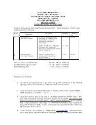
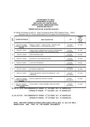
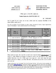
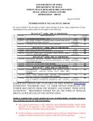
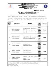

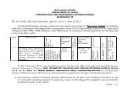
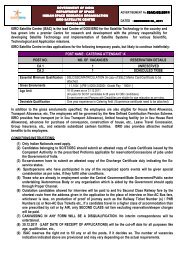
![Government of India Government of India ¢ ] ¢ ] Space ... - ISRO](https://img.yumpu.com/23555817/1/190x245/government-of-india-government-of-india-space-isro.jpg?quality=85)