

Tempering adjustable valve with knob - Caleffi
Tempering adjustable valve with knob - Caleffi
Tempering adjustable valve with knob - Caleffi

Create successful ePaper yourself
Turn your PDF publications into a flip-book with our unique Google optimized e-Paper software.
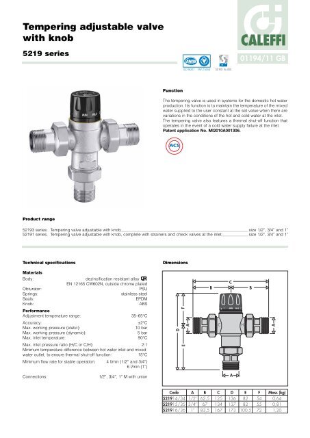
<strong>Tempering</strong> <strong>adjustable</strong> <strong>valve</strong><br />
<strong>with</strong> <strong>knob</strong><br />
5219 series<br />
Product range<br />
Function<br />
01194/11 GB<br />
The tempering <strong>valve</strong> is used in systems for the domestic hot water<br />
production. Its function is to maintain the temperature of the mixed<br />
water supplied to the user constant at the set value when there are<br />
variations in the conditions of the hot and cold water at the inlet.<br />
The tempering <strong>valve</strong> also features a thermal shut-off function that<br />
operates in the event of a cold water supply failure at the inlet.<br />
Patent application No. MI2010A001306.<br />
52193 series. <strong>Tempering</strong> <strong>valve</strong> <strong>adjustable</strong> <strong>with</strong> <strong>knob</strong> size 1/2”, 3/4” and 1”<br />
52191 series. <strong>Tempering</strong> <strong>valve</strong> <strong>adjustable</strong> <strong>with</strong> <strong>knob</strong>, complete <strong>with</strong> strainers and check <strong>valve</strong>s at the inlet size 1/2”, 3/4” and 1”<br />
Technical specifications<br />
Materials<br />
Body: dezincification resistant alloy<br />
EN 12165 CW602N, outside chrome plated<br />
Obturator: PSU<br />
Springs: stainless steel<br />
Seals: EPDM<br />
Knob:<br />
Performance<br />
ABS<br />
Adjustment temperature range: 35–65°C<br />
Accuracy: ±2°C<br />
Max. working pressure (static): 10 bar<br />
Max. working pressure (dynamic): 5 bar<br />
Max. inlet temperature: 90°C<br />
Max. inlet pressure ratio (H/C or C/H): 2:1<br />
Minimum temperature difference between hot water inlet and mixed<br />
water outlet, to ensure thermal shut-off function: 15°C<br />
Minimum flow rate for stable operation: 4 l/min (1/2” and 3/4”)<br />
6 l/min (1”)<br />
Connections: 1/2”, 3/4”, 1” M <strong>with</strong> union<br />
Dimensions<br />
D<br />
F<br />
E<br />
Code<br />
521914/34<br />
521915/35<br />
521916/36<br />
ACCREDITED<br />
ISO 9001 FM 21654<br />
A<br />
A<br />
1/2”<br />
3/4”<br />
1”<br />
B<br />
62,5<br />
67<br />
83,5<br />
ISO 9001 No. 0003<br />
C<br />
B B<br />
2<br />
C<br />
HOT<br />
C<br />
125<br />
134<br />
167<br />
1<br />
MIN MAX 7<br />
A<br />
D<br />
136<br />
137<br />
173<br />
CALEFFI<br />
H<br />
COLD<br />
E<br />
82<br />
82<br />
100,5<br />
F<br />
54<br />
55<br />
72<br />
A<br />
Mass (kg)<br />
0,64<br />
0,81<br />
1,20
Legionella - point of distribution<br />
According to the most recent legislation and standards, in order to<br />
prevent the growth of the dangerous Legionella bacterium in<br />
centralised systems producing domestic hot water <strong>with</strong> storage,<br />
the hot water must be stored at a temperature of at least 60°C.<br />
At this temperature it is certain that the growth of the bacteria will<br />
be totally eliminated.<br />
The adjacent diagram<br />
shows the behaviour of<br />
Legionella Pneumophila<br />
bacteria as the<br />
temperature conditions<br />
of the water containing<br />
the bacteria vary.<br />
To ensure correct<br />
thermal disinfection, it is<br />
necessary to go up to<br />
values of at least 60°C.<br />
Operating principle<br />
20<br />
10<br />
0<br />
The tempering <strong>valve</strong> mixes the hot and cold water at the inlet so as<br />
to maintain the mixed water at a constant set temperature at the<br />
outlet.<br />
A thermostatic element (1) is fully immersed in the mixed water flow<br />
(2). It contracts or expands, moving an obturator (3) which controls<br />
the passage of hot (4) or cold (5) water at the inlet. If the inlet<br />
temperature or pressure changes, the internal element<br />
automatically reacts to restore the set temperature at the outlet.<br />
COLD<br />
5<br />
1<br />
Version <strong>with</strong> strainers and<br />
check <strong>valve</strong>s<br />
70 Instant death of bacteria<br />
60 Death of 90% of bacteria <strong>with</strong>in<br />
2 minutes<br />
50 Death of 90% of bacteria <strong>with</strong>in<br />
2 hours<br />
40<br />
Optimum temperature<br />
30 for growth of bacteria<br />
Bacteria survive but inactive<br />
MIXED<br />
2<br />
4<br />
In this type of system, it often happens that the temperature at the<br />
storage outlet is unstable and highly variable. This occurs because<br />
of multiple operating conditions, in terms of pressure and heat<br />
exchange <strong>with</strong> the primary energy source and the drawn flow rate.<br />
For all these reasons, therefore, a tempering <strong>valve</strong> must be installed<br />
on the hot water storage outlet line, at the inlet point of the<br />
distribution system, which is able to:<br />
- reduce the temperature at the point of distribution to a value lower<br />
than that of the storage, in a controlled way to make it suitable for<br />
domestic use,<br />
- have a temperature adjustment range that makes it possible to<br />
perform a thermal disinfection of the system, should this be<br />
necessary,<br />
- allow the temperature to be adjusted at the desired value, <strong>with</strong> a<br />
tamper-proof locking system,<br />
- keep the distribution temperature constant despite variations in<br />
temperature, inlet pressure and drawn flow rate,<br />
- have a thermal shut-off function that operates in the event of a<br />
cold water supply failure at the inlet.<br />
3<br />
Construction details<br />
Anti-scale materials<br />
The materials used in constructing the tempering <strong>valve</strong> were<br />
selected to eliminate seizing due to limescale deposits. All<br />
functional parts are made using a special anti-scale material <strong>with</strong><br />
low friction coefficient, which ensures that performance is<br />
maintained over time.<br />
Thermal shut-off<br />
In the event of accidental cold water supply failure, the obturator<br />
shuts off the hot water passage, thus preventing the delivery of<br />
mixed water. This performance is guaranteed only when there is a<br />
minimum temperature difference between the inlet hot water and<br />
the outlet mixed water of 15°C.<br />
HOT<br />
Version <strong>with</strong> strainers and<br />
check <strong>valve</strong>s
Hydraulic characteristics<br />
∆p (bar)<br />
1,5<br />
1,0<br />
0,5<br />
0,3<br />
0,2<br />
0,1<br />
0,05<br />
0,2<br />
5<br />
0,5<br />
10<br />
Code ∅ Kv (m 3 /h)<br />
521914/34 1/2” 1.5<br />
521915/35 3/4” 1.7<br />
521916/36 1” 3.0<br />
Application<br />
1<br />
1/2” 3/4” 1”<br />
20<br />
2<br />
50<br />
∆p (m w.g.)<br />
The 5219 series tempering <strong>valve</strong>s are used for applications at the point of<br />
distribution, to control the temperature of the domestic hot water distributed in the<br />
network.<br />
To ensure a stable operation, the tempering <strong>valve</strong> must have a minimum flow rate of<br />
4 l/min (1/2”; 3/4”) and 6 l/min (1”).<br />
Choice of tempering <strong>valve</strong> size<br />
Given the design flow rate, taking into account simultaneous use of the domestic<br />
appliances, the tempering <strong>valve</strong> size should be selected by checking the head loss<br />
on the provided graph. In this case, it is necessary to check the available pressure,<br />
the head loss in the system downstream of the tempering <strong>valve</strong> and the residual<br />
pressure to be guaranteed for user appliances.<br />
Sizing software is available on www.caleffi.it.<br />
Installation<br />
Before installing the tempering <strong>valve</strong>, the connecting pipes should be flushed to<br />
remove any impurities that could impair performance. The installation of strainers of<br />
adequate performance at the water inlet from the water supply network is always<br />
recommended.<br />
The 5219 series tempering <strong>valve</strong>s must be installed according to the diagrams<br />
shown in the instruction sheet or in this leaflet.<br />
The 5219 series tempering <strong>valve</strong>s can be installed in any position, horizontally or<br />
vertically.<br />
The following indications are on the <strong>valve</strong> body:<br />
. hot water inlet, indicated by the letter “H” (Hot)<br />
· cold water inlet, indicated by the letter “C” (Cold)<br />
· mixed water outlet, indicated by the word “MIX”.<br />
5<br />
15<br />
10<br />
5<br />
3<br />
2<br />
1<br />
0,5<br />
Flow rate<br />
(l/min) (m3/h) Recommended flow rate values to<br />
ensure stable operation <strong>with</strong> an<br />
accuracy of ±2°C<br />
Minimum<br />
(m<br />
1/2” 0,24 1,80<br />
3/4” 0,24 2,00<br />
1” 0,36 3,60<br />
3 Maximum*<br />
/h) (m3 * ∆p = 1,5 bar<br />
/h)<br />
Check <strong>valve</strong>s<br />
In systems <strong>with</strong> tempering <strong>valve</strong>s, check <strong>valve</strong>s<br />
must be installed to prevent undesired backflow.<br />
The 5219 series tempering <strong>valve</strong>s are available in<br />
versions complete <strong>with</strong> check <strong>valve</strong>s at the hot and<br />
cold water inlets.<br />
Commissioning<br />
In view of the special applications of the tempering<br />
<strong>valve</strong>, it must be commissioned in accordance <strong>with</strong><br />
current regulations by qualified technicians, using<br />
appropriate temperature measurement equipment.<br />
We recommend using a digital thermometer for<br />
measuring the mixed water temperature.<br />
Temperature adjustment<br />
The temperature is set at the desired value using the<br />
control <strong>knob</strong> <strong>with</strong> the graduated scale on the <strong>valve</strong>.<br />
Locking the setting<br />
Turn the <strong>knob</strong> onto the required number, unscrew<br />
the upper screw, remove the <strong>knob</strong> and put it back<br />
on so that the internal reference couples <strong>with</strong> the<br />
protrusion on the <strong>knob</strong> holder nut.<br />
3<br />
2<br />
1<br />
MIN MA X 7
Application diagrams<br />
T<br />
Ball <strong>valve</strong><br />
Ball <strong>valve</strong> <strong>with</strong> check<br />
<strong>valve</strong><br />
Temperature gauge<br />
Pump<br />
Expansion vessel<br />
Thermostat<br />
Temperature/pressure<br />
safety relief <strong>valve</strong><br />
Safety relief <strong>valve</strong><br />
Pressure reducing <strong>valve</strong><br />
Y-strainer<br />
T<br />
2 1 MIN MAX 7<br />
C H<br />
2 1 MIN MAX 7<br />
C H<br />
SPECIFICATION SUMMARY<br />
5219 series<br />
<strong>Tempering</strong> <strong>valve</strong> <strong>adjustable</strong> <strong>with</strong> <strong>knob</strong>. Connections 1/2” M (3/4” and 1”) <strong>with</strong> union. Dezincification resistant alloy body. Chrome<br />
plated. PSU obturator. Stainless steel springs. EPDM seal elements. ABS control <strong>knob</strong>. Maximum inlet temperature 90°C.<br />
Adjustment temperature range 35°C to 65°C. Accuracy ± 2°C. Maximum working pressure (static) 10 bar. Maximum working<br />
pressure (dynamic) 5 bar. Maximum inlet pressure ratio (H/C or C/H) 2:1. Equipped <strong>with</strong> tamper-proof temperature setting lock.<br />
We reserve the right to change our products and their relevant technical data, contained in this publication, at any time and <strong>with</strong>out prior notice.<br />
CALEFFI<br />
CALEFFI S.p.A. · S.R.229, N.25 · 28010 Fontaneto d’Agogna (NO) · Italy · Tel. +39 0322 8491 · Fax +39 0322 863723<br />
· www.caleffi.com · info@caleffi.com ·<br />
© Copyright 2011 <strong>Caleffi</strong><br />
COLD<br />
HOT<br />
COLD<br />
HOT<br />
2 1 MIN MAX 7<br />
C H<br />
COLD<br />
HOT<br />
Water<br />
supply<br />
Water<br />
supply<br />
Water<br />
supply


