
Create successful ePaper yourself
Turn your PDF publications into a flip-book with our unique Google optimized e-Paper software.
Check list<br />
The battery type and charge voltage recommendations are set out<br />
1)Ensure that the inverter has the correct d/c voltage for your boat or<br />
above. For 24V unit x the above by 2. Some battery types may look<br />
vehicle system. ie 12 or 24V.<br />
confusing such as gel usa and gel euro, AGM usa and AGM euro. If<br />
2)Fit as close to the batteries as possible. The shorter the d/c cables the<br />
you find this confusion then join the club, we have had the different<br />
better. Voltage drop on long cables will effect the unit’s performance.<br />
voltage curves supplied to us by different companies form the U.S.A.<br />
3)Do not reverse the cables! Connect the red cable to the positive<br />
and Europe for what we seem the same product, however, it’s not our<br />
terminal and the black cable to the negative terminal of the battery. In<br />
call, we simply supply the options, if in doubt call your battery<br />
the event of reverse polarity the unit could be totally destroyed.<br />
supplier and ask which charge voltage they want you to use for their<br />
4)Always use the inverter in an environment which is<br />
battery type, and select the closest to it. If totally confused then use the<br />
well ventilated, not exposed to direct sunlight or a heat source, away<br />
lower voltage setting until you have had a higher voltage setting<br />
from water, moisture, oil or grease, away from any highly inflammable<br />
confirmed to you by whoever supplied the batteries to you.<br />
substance, out of reach from children.<br />
The de-sulpation cycle on switch position 8 is marked in red because<br />
5)The output voltage of this unit must never be on your AC system at<br />
this is a very dangerous setting if you do not know what your are<br />
the same time as any other a/c source such as the 230V external mains<br />
doing. Before even attempting to use this cycle you must clearly<br />
line or a generator. All external power must go through the <strong>Combi</strong>.<br />
understand what it does and when and how you would use it.<br />
6)Always switch on the <strong>Combi</strong> first, before plugging in any appliance.<br />
What causes sulphation? Sulphation occurs with infrequent use of the<br />
7)Under new electrical legislation only professional electrictians should<br />
batteries, or if the batteries have been left discharged so low that they<br />
install this product.<br />
will not accept a charge. This cycle is a very high voltage charge cycle<br />
Ensure the fitting instructions are fully understood before fitting this<br />
designed to try to break down the sulphate ‘crust’ that is preventing the<br />
product.<br />
plates taking a charge and thus allow the plates to clean up and so<br />
Installation<br />
accept charge once again.<br />
1) Position the unit as close to the main battery bank as possible. How to use this function.<br />
(only suitable for open lead acid batteries)<br />
2) Position in a cool, dry & well ventilated space. 1) Ensure the battery bank is totally isolated from anything else on the<br />
3) Orientation of the unit is not critical. boat or vehicle; the high voltage applied by this setting could destroy<br />
4) Either purchase the standard cable set from <strong>Sterling</strong> which is about all your electronics and other electrical equipment still connected<br />
1.5 metres, or, if using your own cable, use the cable size chart (hence all these instructions are in red, this is a very expensive<br />
provided on the installation drawing to ensure you have thick enough mistake).<br />
cable for the D/C leads. In the event of not being able to get the size 2) Make sure the battery compartment is very well ventilated and<br />
requested (it can be hard to get thick cable) then simply add multiple battery caps are removed.<br />
length of thinner cable, i.e. If you cannot get 90mm cable then use 3 x 3) Switch the battery type selector switch to the correct position, then<br />
30mm cable, at the end of the day its just copper we need.<br />
switch the a/c power on.<br />
5) Fit a fuse suitable for the job, again look at the installation drawing, 4) Because this is such a dangerous setting there is a 4 hr time out<br />
<strong>Sterling</strong> have a full range of high current fuses in the GANLR range of period build into the software, however, on a very large battery bank<br />
gold fuse products, ranging from 100-500 amps. On the d/c side this may not be enough and the unit may need to be switched off and<br />
6) Connect the cables from the batteries to the fuse then to the unit, this on again to do another cycle.<br />
way if there is a fault at the unit the fuse is already in place and this will<br />
be safe. In the event of a isolation switch being used, please ensure the What to expect on this cycle.<br />
rating of the switch can handle the power of the unit.<br />
I would recomend you monitor the voltage of the sulphated battery<br />
7)Ensure the unit is switched off during installation.<br />
bank. When you switch on the cycle the voltage should shoot up to the<br />
8) On the a/c side ensure the shore power (all external a/c sources) are full 15.5 volts very fast (within minutes) this is because the batteries<br />
totally disconnected, connect the output from the inverter to suitable cannot accept the charge (assuming they are sulphated). However,<br />
Residual Current Breaker (R.C.D. for earth protection) and current over a period of 1-2 hrs the voltage should start to drop (as the plates<br />
over-load trips. Fuse the a/c input side depending on through power start to clean and the batteries start to take a charge) the voltage could<br />
requirements, the max through power is 30 amps, so fuse at 40A drop way down to about 12.5 volts then start to rise. This shows the<br />
(allowing also for charger consumption) if you intend to use the full batteries are now taking a charge and starting to fill up. In this case it<br />
through power for standard 13-16 amps throughput then a 20A fuse would be safe to switch the unit off and select your normal charging<br />
would be appropriate.<br />
curve and hopefully this will bring your batteries back from the dead.<br />
9) <strong>Sterling</strong> recommend Multi core tri rated a/c cable, if used on a boat You may need to repeat the process a few times. Please note this is a<br />
or vehicle, as this is much safer where vibration is likely. Only use professional guess tool, which most times helps, but its not magic, so<br />
single solid household a/c cable if the product is being used as a power expect the worst and hope for the best. Never leave a system<br />
source for a house or platform free of vibration.<br />
unattended when on this mode. If the battery temperature reaches<br />
10) Before attempting to switch on the unit, please ensure you have above 50 deg C (i.e. if the batteries are almost too hot to touch) then<br />
selected the correct battery type on the small battery type selector stop the process).<br />
switch on the front of the main box, rotate the switch to your battery Install remote control.<br />
type. The <strong>Pro</strong>gressive charge control software will automatically adjust<br />
Isolate the unit before attempting this so there are no high voltages.<br />
The local control panel on the front of the unit can also be used as a<br />
remote control, simply slide the 2 end sections off to reveal the screws<br />
for battery bank size and state.<br />
Batter Type Selector, for 24V x voltages by 2<br />
Switch setting Boost Float holding the panel onto the main box, carefully remove the panel and<br />
0) to be used by factory for set up disconnect it from the connection socket behind the unit.<br />
1)Gel usa 14 13.7 Fill the hole on the main unit using the blank replica of the remote<br />
2)AGM 1 14.1 13.4 control unit.<br />
3)AGM 2 14.6 13.7<br />
Using the remote cable supplied then re-connect the panel to the unit<br />
4)sealed lead acid 14.4 13.6<br />
<strong>Combi</strong>: Operation and what to expect<br />
5)gel euro 14.4 13.8<br />
1) After the unit is installed, using the panel on the front of the unit,<br />
6)open lead acid 14.8 13.3<br />
and with the shore power ( 230V a/c) still disconnected, switch the<br />
7)calcuim 15.1 13.6<br />
unit on. The LEDs will cycle through their test routine, then the unit<br />
8)de sulphation 15.5 4 hrs then off<br />
should go into inverter mode and 230V should be produced on the<br />
output a/c terminals (provided the batteries are over 11 volts).<br />
9)not used<br />
FOR 24 VOLTS<br />
X 2<br />
V<br />
O<br />
L<br />
T<br />
S<br />
15<br />
14.5<br />
14<br />
13.5<br />
13<br />
12.5<br />
12<br />
11.5<br />
11<br />
10.5<br />
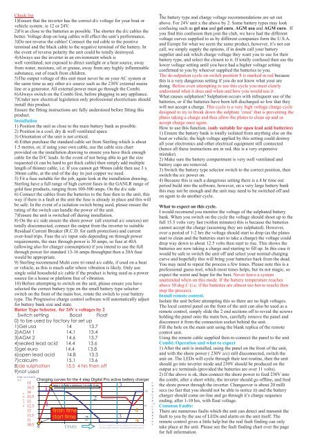
Charging curves for the 4 step Digital <strong>Pro</strong> active battery charger<br />
1<br />
1<br />
time x 10, with a minimum 1 hr max 12 hrs<br />
finish time<br />
start time<br />
TIME<br />
2<br />
2<br />
FLOAT 13.5 V<br />
3<br />
3<br />
4<br />
4<br />
FULL CURRENT AVAILABLE ON FLOAT FOR<br />
ON BOARD SUPPLY IN POWER PACK MODE<br />
100<br />
50<br />
0<br />
C<br />
H<br />
A<br />
R<br />
G<br />
E<br />
R<br />
%<br />
C<br />
U<br />
R<br />
R<br />
E<br />
N<br />
T<br />
2) If the above is ok, then connect the shore power to feed 230V into<br />
the combi, after a short while, the inverter should go offline, and feed<br />
the shore power through the inverter. Changeover is about 20 milli<br />
secs (so fast that you should not be able to notice it) and the battery<br />
charger should come on-line and go through it’s charge sequence<br />
ending, after 1-10 hrs, with float voltage.<br />
Common Faults:<br />
There are numerous faults which the unit can detect and transmit the<br />
fault to you by the use of LEDs and alarm on the unit itself. The<br />
remote control gives a little help but the real fault finding can only<br />
take place at the unit. Please see the fault finding chart over the page<br />
for full information.