Users Manual BTS 4000.pdf - Jotron
Users Manual BTS 4000.pdf - Jotron
Users Manual BTS 4000.pdf - Jotron
You also want an ePaper? Increase the reach of your titles
YUMPU automatically turns print PDFs into web optimized ePapers that Google loves.
Handbook page<br />
1/52<br />
DOCUMENTATION HANDBOOK<br />
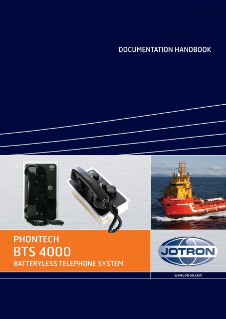
PHONTECH<br />
<strong>BTS</strong> 4000<br />
BATTERYLESS TELEPHONE SYSTEM<br />
www.jotron.com
<strong>BTS</strong> 4000 Handbook contents:<br />
Handbook page:<br />
Batteryless Telephone System 4000<br />
− System Description ……...…………………………………………… 08400-006-DE .………… 1<br />
− External Connection , 1L. Configuration example, 4050/4051 …..… 08400-006-EC-01 ....…… 20<br />
− External Connection , 12L. Configuration example, 4060/4061 …..... 08400-006-EC-02 ....…… 21<br />
− External Connection , 24L. Configuration example, 4040/4000 …..… 08400-006-EC-03 ....…… 22<br />
4040, Batteryless Telephone, 24L<br />
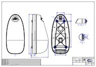
− Mechanical Layout (flush mounted) ……………….……………….. 08400-001-ML .………… 23<br />
− Mechanical Layout (bulkhead mounted) …………..……………….. 08400-001-ML-02 ……… 24<br />
− External Connection ….....…………………………………………… 08400-001-EC ..………… 25<br />
4050, Batteryless Telephone, 1L<br />
− Mechanical Layout (flush mounted) ……………….……………….. 08400-002-ML .………… 26<br />
− Mechanical Layout (bulkhead mounted) …………..……………….. 08400-002-ML-02 ……… 27<br />
− External Connection ….....…………………………………………… 08400-002-EC ..………… 28<br />
4051, Batteryless Telephone w/Amp, 1L<br />
− Mechanical Layout (flush mounted) ……………….……………….. 08400-003-ML .………… 29<br />
− Mechanical Layout (bulkhead mounted) …………..……………….. 08400-003-ML-02 ……… 30<br />
− External Connection ….....…………………………………………… 08400-003-EC ..………… 31<br />
4060, Batteryless Telephone, 12L<br />
− Mechanical Layout (flush mounted) ……………….……………….. 08400-004-ML .………… 32<br />
− Mechanical Layout (bulkhead mounted) …………..……………….. 08400-004-ML-02 ……… 33<br />
− External Connection ….....…………………………………………… 08400-004-EC ..………… 34<br />
4061, Batteryless Telephone w/Amp, 12L<br />
− Mechanical Layout (flush mounted) ……………….……………….. 08400-005-ML .………… 35<br />
− Mechanical Layout (bulkhead mounted) …………..……………….. 08400-005-ML-02 ……… 36<br />
− External Connection ….....…………………………………………… 08400-005-EC ..………… 37<br />
99400-011, Relay Switch Board for <strong>BTS</strong><br />
− Board Layout ………………..................................……………….. 99400-011-LO ...………… 38<br />
− Description …………..……...............................................………….. 99400-011-CA ……......… 39<br />
− Circuit Diagram …............…………………………………………… 99400-011-CD ..………… 40<br />
Amplifier unit, 4000<br />
− Mechanical Layout ……...…………………………………………… 87400-004-ML .………… 41<br />
− External Connection ………....……………….……………………… 87400-004-EC ..………… 42<br />
4018, Headset Plugbox with Call Stop<br />
− Mechanical Layout ……...…………………………………………… 09908-007-ML .………… 43<br />
− External Connection ………....……………….……………………… 09908-007-EC ..………… 44<br />
9000, Relay Unit<br />
− Mechanical Layout ……...…………………………………………… 09908-009-ML .………… 45<br />
− External Connection ………....……………….……………………… 09908-009-EC ..………… 46<br />
Headset with PTT Switch, 0018<br />
− Mechanical Layout ……...…………………………………………… 88000-005-ML .………… 47<br />
Headset with Chest Switch, 9010<br />
− Mechanical Layout ……...…………………………………………… 00900-002--ML .………… 48<br />
Ver 2010.09
Handbook page<br />
1/50<br />
Doc.No.: 08400-006-DE<br />
BATTERYLESS TELEPHONE SYSTEM 4000<br />
UNITS: 4000 / 4040 / 4050 / 4051 / 4060 / 4061<br />
SYSTEM DESCRIPTION.<br />
Contents:<br />
1. GENERAL DESCRIPTION ............................................................................................................. 3<br />
2. LIST OF TELEPHONE UNITS ....................................................................................................... 4<br />
2.1. 24 LINES BATTERYLESS TELEPHONE, TYPE 4040 ......................................................... 4<br />
2.2. 12 LINES BATTERYLESS TELEPHONE WITH INTEGRATED AMP, TYPE 4061 .......... 5<br />
3. ADDITIONAL EQUIPMENT .......................................................................................................... 6<br />
3.1. AMPLIFIER UNIT, TYPE 4000 ............................................................................................... 6<br />
3.2. RELAY UNIT, TYPE 9000 ...................................................................................................... 7<br />
3.3. PLUGBOX FOR HEADSET WITH CALL STOP, TYPE 4018 .............................................. 7<br />
3.4. HEADSET WITH PTT SWITCH AND PLUG, TYPE 0018 ................................................... 8<br />
3.5. HEADSET WITH PTT SWITCH, TYPE 9010 ........................................................................ 8<br />
3.6. PLUG-IN RELAY MODULE (BRD 99400-011) .................................................................... 9<br />
4. LIST OF FACILITIES ...................................................................................................................... 9<br />
4.1. BATTERYLESS AMPLIFIERT UNIT, TYPE 4000 ............................................................... 9<br />
4.2. 24 LINES BATTERYLESS TELEPHONE 4040 ................................................................... 10<br />
4.3. SINGLE LINE BATTERYLESS TELEPHONE, TYPE 4050 ............................................... 10<br />
4.4. SINGLE LINE BATTERYLESS TELEPHONE WITH AMPLIFIER, TYPE 4051 .............. 10<br />
4.5. 12 LINES BATTERYLESS TELEPHONE, TYPE 4060 ....................................................... 10<br />
5. BASIC MEANS OF OPERATION ................................................................................................ 11<br />
5.1. GENERAL ............................................................................................................................... 11<br />
5.2. MAKE A CALL TO ANOTHER STATION .......................................................................... 11<br />
5.3. ANSWER A CALL FROM ANOTHER STATION ............................................................... 11<br />
5.4. TERMINATE A CONVERSATION ...................................................................................... 11<br />
5.5. HEADSET (TYPE 9010) OPERATION ................................................................................. 12<br />
1 08.07.2010 REVISION, EM 1289 ASK ASK<br />
0 27.10.2008 FINAL DOCUMENTATION CD<br />
REV No: ISSUE DATE REASON FOR ISSUE PREPARED CHECKED APPROVED<br />
TITLE: BATTERYLESS TELEPHONE SYSTEM 4000<br />
DESCRIPTION<br />
This document is the property of JOTRON<br />
PHONTECH and must not be copied or shown to a<br />
third person without our written consent. In the<br />
interest of product improvement, JOTRON<br />
PHONTECH reserves the right to alter<br />
specification and design without notice.<br />
SIZE: -- UED no: --<br />
DOC no: 08400-006-DE<br />
FILE NAME:<br />
08400-006-DE.doc<br />
Page 1 of 19
Handbook page<br />
2/50<br />
Doc.No.: 0400-000-DE<br />
5.5.1. Make a call out from the telephone to another station ......................................................... 12<br />
5.5.2. Answer a call from another station ...................................................................................... 12<br />
6. INSTALLATION............................................................................................................................ 13<br />
6.1. SYSTEM CONFIGURATION ................................................................................................ 13<br />
6.2. MOUNTING ............................................................................................................................ 13<br />
6.3. COMPASS SAFE DISTANCE ............................................................................................... 13<br />
6.4. CABLE TERMINATION ....................................................................................................... 13<br />
6.5. CABLE REQUIREMENTS .................................................................................................... 14<br />
6.6. GLANDING ............................................................................................................................ 14<br />
6.7. SCREENING ........................................................................................................................... 14<br />
6.8. MARKING .............................................................................................................................. 14<br />
6.9. FASTENING ........................................................................................................................... 14<br />
6.10. PRESERVATION ................................................................................................................ 14<br />
6.11. VOLUME ADJUSTMENT ................................................................................................. 15<br />
7. TECHNICAL DATA. TELEPHONE UNITS 4040/4050/4051/4060/4061 ................................... 16<br />
8. SINGLE LINE DIAGRAM – SINGLE LINE SYSTEM ............................................................... 17<br />
9. SINGLE LINE DIAGRAM – 12 LINE SYSTEM ......................................................................... 18<br />
10. SINGLE LINE DIAGRAM – 24 LINE SYSTEM ...................................................................... 19<br />
Page 2 of 19
Handbook page<br />
3/50<br />
Doc.No.: 08400-006-DE<br />
1. GENERAL DESCRIPTION<br />
The batteryless telephone system is developed and manufactured <strong>Jotron</strong> Phontech as.<br />
The different modules in the system are designed to meet the need and demand for nonpowered<br />
internal (sound powered) emergency communication on ships.<br />
The system is basically divided into three different configurations, the single line system<br />
(4050/4051) for point-to point communication between two stations, like the bridge and the<br />
machinery spaces. The 12 lines system, (4060/4061) for up to 12 stations. And the 24 lines<br />
system (4000/4040) for up to 24 stations.<br />
The compact design provides good installation possibilities, with a minimum space<br />
requirement.<br />
The flush mounting units are adapted to the DIN 144x144 module standard for easy mounting<br />
in the bridge and engine control consoles.<br />
The modules may also be wall mounted; this requires a wall mounting back-box. (Optional)<br />
The different units are prepared for gland mounting, i.e. holes have been fitted for a wide range<br />
of cable glands.<br />
Several additional types of equipment may be connected to the Batteryless Telephone System,<br />
like headset connector boxes, extra headsets, power supplies, external signal devices relay<br />
switch boxes, etc.<br />
Page 3 of 19
Handbook page<br />
4/50<br />
Doc.No.: 08400-006-DE<br />
2. LIST OF TELEPHONE UNITS<br />
Type <strong>BTS</strong> 4040.<br />
Type <strong>BTS</strong> 4050<br />
Type <strong>BTS</strong> 4051<br />
Type <strong>BTS</strong> 4060<br />
Type <strong>BTS</strong> 4061<br />
24 lines batteryless telephone.<br />
Single line batteryless telephone.<br />
Single line batteryless telephone with integrated amplifier<br />
12 lines batteryless telephone.<br />
12 lines batteryless telephone with integrated amplifier<br />
2.1. 24 LINES BATTERYLESS TELEPHONE, TYPE 4040<br />
PHONTECH 4040<br />
.<br />
Page 4 of 19
Handbook page<br />
5/50<br />
Doc.No.: 08400-006-DE<br />
2.2. 12 LINES BATTERYLESS TELEPHONE WITH INTEGRATED AMP, TYPE<br />
4061<br />
PHONTECH 4061<br />
.<br />
Page 5 of 19
Handbook page<br />
6/50<br />
Doc.No.: 08400-006-DE<br />
3. ADDITIONAL EQUIPMENT<br />
Type <strong>BTS</strong> 4000. Amplifier unit (separate) for a 4040 / 24 lines system<br />
Type 9000 Relay unit (for additional signal device)<br />
Type 4018 Plugbox for headset with “Call stop”.<br />
Type 0018 Headset with PTT switch and plug. (Connects to 4018)<br />
Type 9010 Headset with PTT switch. (Connects directly to the telephone unit)<br />
BRD 99400-011 Plug-in relay module for external signal device.<br />
Type 4052 Junction box type I (12 ext.)<br />
Type 4053 Junction box type II (8 ext.)<br />
3.1. AMPLIFIER UNIT, TYPE 4000<br />
.<br />
Page 6 of 19
Handbook page<br />
7/50<br />
Doc.No.: 08400-006-DE<br />
3.2. RELAY UNIT, TYPE 9000<br />
3.3. PLUGBOX FOR HEADSET WITH CALL STOP, TYPE 4018<br />
.<br />
Page 7 of 19
Handbook page<br />
8/50<br />
3.4. HEADSET WITH PTT SWITCH AND PLUG, TYPE 0018<br />
Doc.No.: 08400-006-DE<br />
3.5. HEADSET WITH PTT SWITCH, TYPE 9010<br />
9 meter CABLE<br />
.<br />
Page 8 of 19
Handbook page<br />
9/50<br />
Doc.No.: 08400-006-DE<br />
3.6. PLUG-IN RELAY MODULE (BRD 99400-011)<br />
A relay module for activation of external signal device can be installed in the betteryless<br />
telephones: 4040 / 4050 / 4051 / 4060 / 4061<br />
The relay module is to be mounted by the installer. The unit is delivered separately, and is to be<br />
plugged into the appropriate telephone unit.<br />
• Open the backbox on the telephone unit.<br />
• Plug the relay unit into the receptacle on the PCB inside the telephone. Make sure the<br />
connector pins make contact.<br />
• Snap the stand off`s (2pcs) into the holes in the PCB.<br />
• Make the connections according to the installation drawings 99400-017-EC or 99400-018-<br />
EC.<br />
• If DC voltage is used, make sure the polarity is correct. (Indication on the dwgs. 99400-<br />
017-EC and 99400-018-EC)<br />
4. LIST OF FACILITIES<br />
4.1. BATTERYLESS AMPLIFIERT UNIT, TYPE 4000<br />
- Interface for up to 24 batteryless telephones<br />
- Extreme low current drain speech amplifier.<br />
.<br />
Page 9 of 19
Handbook page<br />
10/50<br />
Doc.No.: 08400-006-DE<br />
4.2. 24 LINES BATTERYLESS TELEPHONE 4040<br />
- Handset with PTT button.<br />
- Noise cancelling microphone.<br />
- Piezo- electric buzzer for call indication.<br />
- Call led.<br />
- 20 seconds call delay timer. (24 VDC required)<br />
- Call stop button.<br />
- Call line rotary selector switch.<br />
- Back lightning of the line selector and the call stop button. (24 VDC required)<br />
4.3. SINGLE LINE BATTERYLESS TELEPHONE, TYPE 4050<br />
- Handset with PTT button.<br />
- Noise cancelling microphone.<br />
- Piezo- electric buzzer for call indication.<br />
- Call led.<br />
- 20 seconds call delay timer. (24 VDC required)<br />
- Call stop button.<br />
- Back lightning of the call stop button. (24 VDC required)<br />
4.4. SINGLE LINE BATTERYLESS TELEPHONE WITH AMPLIFIER, TYPE 4051<br />
- Handset with PTT button.<br />
- Noise cancelling microphone.<br />
- Piezo- electric buzzer for call indication.<br />
- Call led.<br />
- 20 seconds call delay timer. (24 VDC required)<br />
- Call stop button.<br />
- Back lightning of the call stop button. (24 VDC required)<br />
- Extreme low current drain speech amplifier.<br />
4.5. 12 LINES BATTERYLESS TELEPHONE, TYPE 4060<br />
- Handset with PTT button.<br />
- Noise cancelling microphone.<br />
- Piezo- electric buzzer for call indication.<br />
- Call led.<br />
- 20 seconds call delay timer. (24 VDC required)<br />
- Call stop button.<br />
- Call line rotary selector switch.<br />
- Back lightning of the line selector and the call stop button. (24 VDC required)<br />
.<br />
Page 10 of 19
Handbook page<br />
11/50<br />
4.6. 12 LINES BATTERYLESS TELEPHONE WITH AMPLIFIER, TYPE 4061<br />
Doc.No.: 08400-006-DE<br />
- Handset with PTT button.<br />
- Noise cancelling microphone.<br />
- Piezo - electric buzzer for call indication.<br />
- Call led.<br />
- 20 seconds call delay timer. (24 VDC required)<br />
- Call stop button.<br />
- Call line rotary selector switch.<br />
- Back lightning of the line selector and the call stop button. (24 VDC required)<br />
- Extreme low current drain speech amplifier.<br />
5. BASIC MEANS OF OPERATION<br />
5.1. GENERAL<br />
The batteryless telephone system is operated by means of the handset with PTT switch,<br />
the call line selector switch, (not 4050/4051) and the call generator crank.<br />
There is no priority between units in the system and several users can use the system<br />
simultaneously. All users will then join the same conversation/conference call.<br />
The units are equipped with screw terminals for connection of a headset, type 9010.<br />
5.2. MAKE A CALL TO ANOTHER STATION<br />
- Lift the handset. (See illustration next page)<br />
- Select the line by means of the line selector (not applicable to 4050/4051)<br />
- Crank the generator 3-5 turns.<br />
5.3. ANSWER A CALL FROM ANOTHER STATION<br />
- The telephone will sound the call tone and light the call indicator led (red)<br />
- Lift the handset (See illustration next page) and press the PTT button.<br />
Keep the PTT button pressed at all times during conversation.<br />
- Optional headset: Set the PTT switch to ON and answer the call.<br />
- If external power is connected to the system, the call delay timer will keep the call<br />
indicator led lit (green) for about 30 seconds. Press the “CALL STOP” button (on the<br />
telephone or the headset plugbox, type 4018) to turn it off manually before automatic<br />
time out.<br />
- Additional external signal devices will be activated together with the call indicator led.<br />
5.4. TERMINATE A CONVERSATION<br />
- Replace the handset in the holder. (See illustration next page)<br />
.<br />
Page 11 of 19
Handbook page<br />
12/50<br />
Doc.No.: 08400-006-DE<br />
5.5. HEADSET (TYPE 9010) OPERATION<br />
5.5.1. Make a call out from the telephone to another station<br />
- Put the headset on, with the microphone close to your mouth.<br />
- Select the line by means of the line selector (not applicable to 4050/4051),<br />
- Crank the generator (on the telephone) 3-5 turns.<br />
- When the call is answered, press the PTT -switch temporary on to talk or push it<br />
in/upwards for locked operation (handsfree).<br />
- After the conversation, release the PTT-switch. From locked position press the button<br />
downwards.<br />
5.5.2. Answer a call from another station<br />
- Put the headset on, with the microphone close to your mouth.<br />
- Press the PTT -switch temporary on to talk or push it in/upwards for locked operation<br />
(handsfree).<br />
- After the conversation, release the PTT-switch. From locked position press the button<br />
downwards.<br />
- Replace the headset to its stowage position<br />
ON/OFF HOOK HANDSET MOTION:<br />
.<br />
Page 12 of 19
Handbook page<br />
13/50<br />
Doc.No.: 08400-006-DE<br />
6. INSTALLATION<br />
6.1. SYSTEM CONFIGURATION<br />
The system is to be configured by the installer. Each telephone must be connected to<br />
different “call number” with regards to the Line selector (rotary switch). This is done by<br />
means of a link connection in each telephone.<br />
In a system consisting of 4040 telephones (up to 24 lines) this link is between terminal 29<br />
and the required extension/call number terminal (1-24). Ref drawing 92400-008-EC.<br />
In a 4050/4051 telephone point-to-point configuration the call link is made by means of<br />
connecting terminal 1 of one telephone to terminal 13 (Call input) of the other and vice<br />
versa. Ref drawing 99400-017-EC.<br />
In a 4060/4061 telephone configuration (up to 12 lines) the link is to be connected between<br />
terminal 13 and the desired call number. (1-12). Ref drawing 99400-018-EC.<br />
6.2. MOUNTING<br />
The telephone units (all types) are delivered for flush mounting. Optional wall mounting boxes<br />
are delivered upon request.<br />
<strong>Jotron</strong> Phontech as highly recommends the use of junction boxes for the external cable<br />
distribution.<br />
Prepared junction boxes, type 4052 and 4053 are available.<br />
The sub-units (4000/4018/9000) are delivered with wall mounting box as standard.<br />
6.3. COMPASS SAFE DISTANCE<br />
Compass type<br />
Safe distance<br />
<strong>BTS</strong> 4000 / 4040 / 4050 /<br />
4051 / 4060 / 4061<br />
Standard 1,7m<br />
Steering<br />
0,95m<br />
Stand by steering Emergency<br />
6.4. CABLE TERMINATION<br />
All terminations must be done according to the External Cabling diagrams (example). Ref<br />
chapter 6.1 above.<br />
.<br />
Page 13 of 19
Handbook page<br />
14/50<br />
Doc.No.: 08400-006-DE<br />
6.5. CABLE REQUIREMENTS<br />
All cables used with the Batteryless Telephone System to be of approved ship cable type.<br />
ESPECIALLY IMPORTANT:<br />
! Common outer screen<br />
! Individually twisted pairs<br />
! Recommended minimum conductor area is 0.50 mm²<br />
! All cabling in the batteryless telephone system to be a separate network<br />
! DO NOT COMBINE WITH OTHER CABLES. THIS IS TO PREVENT<br />
DISTURBANCE AND NOISE CAUSED BY INTERFERENCE.<br />
6.6. GLANDING<br />
The cables enter the units by means of cable glands. Where cable glands are not supplied from<br />
the factory, the installer must adapt the glands to the actual cable outer diameter. This is to<br />
obtain the specified ingress protection and cable relief.<br />
6.7. SCREENING<br />
The cable screen must be terminated to the ships GND in the “main unit” (4051/4061). The<br />
cable screen must be connected through the junction box(s) and terminated in terminal 21<br />
(terminal 35 in 4040) or earth stud in all telephones. Ref chapter 6.1 above.<br />
6.8. MARKING<br />
Each cable to be marked with cable number.<br />
Each conductor to be marked with the specific termination number.<br />
Please note that <strong>BTS</strong> telephones uses plug-able screw terminals as standard. This is to make the<br />
installation and service work as smooth as possible.<br />
6.9. FASTENING<br />
Where applicable, the cables and the conductors shall be strapped to the structure.<br />
6.10. PRESERVATION<br />
Prior to, during, and after completion of the installation the equipment surfaces to be protected<br />
against acid holding fluids, pollution, moist, impacts etc.<br />
.<br />
Page 14 of 19
Handbook page<br />
15/50<br />
Doc.No.: 08400-006-DE<br />
This in order to avoid damaged equipment for which <strong>Jotron</strong> Phontech will void warranty<br />
claims.<br />
6.11. VOLUME ADJUSTMENT<br />
Please note that volume adjustment is preset to a normal environment. It is not possible to make<br />
individual volume adjustments on the telephones, but there is a common volume adjustment for<br />
the whole system.<br />
This is located in the system amplifier either as trimming potentiometer R12 in the 4000 unit or<br />
RV1 in the 4051/4061 units.<br />
R12 POSITION IN THE 4000 UNIT (BRD 87400-001):<br />
.<br />
Page 15 of 19
Handbook page<br />
16/50<br />
Doc.No.: 08400-006-DE<br />
RV1 POSITION IN THE 4051/4061 UNITS (BRD 99400-001):<br />
7. TECHNICAL DATA. TELEPHONE UNITS 4040/4050/4051/4060/4061<br />
Dimensions flush mounting:<br />
240 x 144 x 70 mm. (h x w x d)<br />
Cut- out measurement flush mounting:<br />
212 x 116 mm. (h x w)<br />
Dimensions wall mounting wall mounting box included:<br />
242 x 146 x 73 mm. (h x w x d)<br />
Type 4050/51/60/61: add 78 mm to depth for handset.<br />
Weight flush mounted:<br />
Weight wall mounted:<br />
1.4 kg.<br />
1.8 kg.<br />
Operation voltage 24 VDC (optional)<br />
Ingress protection: IP 44.<br />
Technical data for substations etc. see data sheets for each unit.<br />
.<br />
Page 16 of 19
Handbook page<br />
17/50<br />
Doc.No.: 08400-006-DE<br />
8. SINGLE LINE DIAGRAM – SINGLE LINE SYSTEM<br />
.<br />
Page 17 of 19
4 0 1 8<br />
H E A D S E T<br />
C A L L<br />
S T O P<br />
Handbook page<br />
18/50<br />
Doc.No.: 08400-006-DE<br />
9. SINGLE LINE DIAGRAM – 12 LINE SYSTEM<br />
.<br />
Page 18 of 19
PHONTECH 4040<br />
PHONTECH 4040 PHONTECH 4040<br />
PHONTECH 4040<br />
PHONTECH 4040<br />
PHONTECH 4040<br />
4 0 1 8<br />
H E A D S E T<br />
C A L L<br />
S T O P<br />
PHONTECH 4040<br />
Handbook page<br />
19/50<br />
Doc.No.: 08400-006-DE<br />
10. SINGLE LINE DIAGRAM – 24 LINE SYSTEM<br />
.<br />
Page 19 of 19
Handbook page<br />
20/50
Handbook page<br />
21/50
Handbook page<br />
22/50
Handbook page<br />
23/50
Handbook page<br />
24/50
Handbook page<br />
25/50
Handbook page<br />
26/50
Handbook page<br />
27/50
Handbook page<br />
28/50
Handbook page<br />
29/50
Handbook page<br />
30/50
Handbook page<br />
31/50
Handbook page<br />
32/50
Handbook page<br />
33/50
Handbook page<br />
34/50
Handbook page<br />
35/50
Handbook page<br />
36/50
Handbook page<br />
37/50
Handbook page<br />
38/50
Handbook page<br />
39/50<br />
Doc.No.: 99400-011-CA<br />
RELAY SWITCH BOARD FOR BATTERYLESS SYSTEM<br />
99400-011<br />
DESCRIPTION<br />
The Batteryless Telephone Board 99400-001 is designed and produced by <strong>Jotron</strong> Phontech AS.<br />
The board is a plug-in module supporting switching facility for external signal device in the batteryless<br />
telephone system.<br />
The Relay board is compatible with <strong>BTS</strong> telephone types 4040 (Ver 05827), 4050, 4051, 4060 and<br />
4061.<br />
Switching capacity:<br />
24 VDC: 150 VA<br />
115 VAC: 700 VA<br />
220 VAC: 1500 VA<br />
Operation voltage:<br />
Relay coil:<br />
24 VDC<br />
2 16.07.2010 REVISION, EM 1289 ASK ASK<br />
1 20.08.2009 REVISION, EM 1213 CD<br />
0 09.05.2001 DVM COMPLETION t.ly<br />
REV No: ISSUE DATE REASON FOR ISSUE PREPARED CHECKED APPROVED<br />
TITLE: RELAY SWITCH BOARD FOR BATTERYLESS<br />
SYSTEM<br />
DESCRIPTION<br />
This document is the property of JOTRON<br />
PHONTECH and must not be copied or shown to a<br />
third person without our written consent. In the<br />
interest of product improvement, JOTRON<br />
PHONTECH reserves the right to alter<br />
specification and design without notice.<br />
SIZE: --<br />
UED no: M002<br />
DOC no: 99400-011-CA<br />
FILE NAME:<br />
99400-011-CA.doc<br />
Page 1 of 1
Handbook page<br />
40/50
Handbook page<br />
41/50
Handbook page<br />
42/50
Handbook page<br />
43/50
Handbook page<br />
44/50
Handbook page<br />
45/50
Handbook page<br />
46/50
Handbook page<br />
47/50
Handbook page<br />
48/50
Handbook page<br />
49/50<br />
Bilde omslag bak.indd 1 16.06.2009 08:45:31
Handbook page<br />
50/50<br />
www.jotron.com<br />
Generell bakside.indd 1 30.01.2009 12:54:47


