IOM - Maxinex - JT Day Pty Ltd
IOM - Maxinex - JT Day Pty Ltd
IOM - Maxinex - JT Day Pty Ltd

You also want an ePaper? Increase the reach of your titles
YUMPU automatically turns print PDFs into web optimized ePapers that Google loves.
Chalmit Lighting<br />
_<br />
_<br />
_<br />
<strong>IOM</strong> - <strong>Maxinex</strong> Floodlight<br />
Issue 00<br />
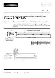
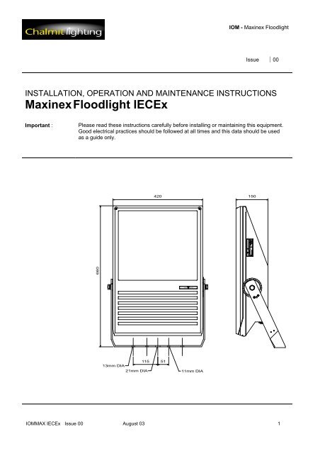
INSTALLATION, OPERATION AND MAINTENANCE INSTRUCTIONS<br />
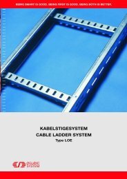
<strong>Maxinex</strong> Floodlight IECEx<br />
Important :<br />
Please read these instructions carefully before installing or maintaining this equipment.<br />
Good electrical practices should be followed at all times and this data should be used<br />
as a guide only.<br />
CHALMIT LIGHTING LTD,<br />
Chalmit Lighting 388 HILLINGTON ROAD,GLASGOW,UK<br />
SITE 0990<br />
MAXINEX 250W SER.No.98WO _ __ CE 600<br />
BAS97ATEX4368<br />
LAMPSON/T 250<br />
II 3G Ex nR II<br />
Tamb -40 TO +55°C IP66/67<br />
SUPPLY:- 240 V 50<br />
ISOLATE SUPPLY BEFORE OPENING<br />
W<br />
T 3<br />
Hz<br />
420<br />
150<br />
660<br />
115 51<br />
13mm DIA<br />
21mm DIA<br />
11mm DIA<br />
<strong>IOM</strong>MAX IECEx Issue 00 August 03 1
<strong>IOM</strong> - <strong>Maxinex</strong> Floodlight<br />
0.0 Specification and ATEX Declaration<br />
Type of Protection Ex nR (non-sparking) (restricted breathing)<br />
Protection Standard IEC 60079-15<br />
Area of Application Zone 2 areas to IEC 60079-10 and installation to IEC 60079-14<br />
Equipment Coding Ex nR II T2/T3/T4 (Refer to Table 0 for Tamb)<br />
IECEx Certificate IECEx certificate of conformity IECEx ITS 03.0004<br />
Ingress Protection IP66 and IP67 to IEC 60529<br />
1.0 Introduction - <strong>Maxinex</strong> Floodlight<br />
1.1 General<br />
The type of protection is Ex nR using a restricted breathing enclosure. It is available with wide (mottled) or<br />
narrow (specular) reflectors.<br />
Note : Lamp ranges, maximum ambient and surface temperature ratings are as outlined in TABLE 0.<br />
1.2 Application<br />
The luminaire is designed to be safe in normal operation.<br />
The luminaire should not be used in conditions where there are environmental, vibration or shock conditions<br />
above the normal for fixed installations.<br />
The gaskets should not be exposed to hydrocarbons in liquid or high concentration vapour states.<br />
The body material is made from marine grade aluminium, copper free.<br />
The luminaire is suitable for applications where Ex n apparatus is used. The application is for ignitable gas<br />
atmospheres. The type examination does not address suitability for dusts or portable applications.<br />
2.0 Storage<br />
Luminaires and control gear boxes are to be stored in cool dry conditions preventing ingress of moisture and<br />
condensation. Any specific instructions concerning emergency luminaires must be complied with.<br />
3.0 Installation and Safety<br />
3.1 General<br />
There are no health hazards associated with this product whilst in normal use. However, care should be<br />
exercised during the following operations. Installation should be carried out in accordance with IEC 60079-14 or<br />
the local hazardous area codes of practice whichever is appropriate.<br />
Your attention is drawn to the paragraphs (i) 'Electrical Supplies', (ii) 'Electrical Fault Finding and Replacement'<br />
and (iii) 'Inspection and Maintenance'. The luminaires are Class 1 and should be effectively earthed.<br />
The luminaires are quite heavy and suitable means of handling on installation must be provided.<br />
Certification details on the rating plate must be verified against the application requirements before installation.<br />
The information in this leaflet is correct at the time of publication. The company reserves the right to make<br />
specification changes as required.<br />
3.2 Tools<br />
A cross head screwdriver blade to open the cover.<br />
19mm A/F spanner, 3mm and 5mm flat blade screwdriver.<br />
Pliers, knife, wire strippers/cutters.<br />
3.3 Electrical Supplies<br />
The supply voltage and frequency should be specified when ordering a maximum voltage variation of +6%/-6%<br />
on the nominal is expected. (The safety limit for T rating is +10%). Luminaires should not be operated<br />
continuously at more than +6%/-10% of the rated supply voltage of the control gear or tapping. The user must<br />
determine the actual underlying site supply and purchase or adjust accordingly. In some cases, the luminaires<br />
<strong>IOM</strong>MAX IECEx Issue 00 August 03 2
<strong>IOM</strong> - <strong>Maxinex</strong> Floodlight<br />
have multi-tapped control gear which can be set to a range of 50 and 60Hz voltages. The tappings are shown on<br />
the control gear and the limits are shown on the rating plate. If the equipment is located in high or low voltage<br />
sections of the system, an appropriate voltage tap should be selected to obtain the best lamp performance, but<br />
care must be taken to log or mark the equipment so that the tapping is re-set if the equipment is relocated. If in<br />
doubt, tappings should be set on the high side. 10V Max. drop is desirable for HPS and required for MBI. All<br />
circuits use S.I.P. (superimposed pulse) ignitors. This means that there are only two connections to the choke,<br />
so tap selection is obvious. Where supply conditions include significant harmonics, the PFC can be omitted.<br />
Where shore or construction site supplies are used, which are different to the service location supplies, tappings<br />
should be re-set. If not, advice on the effect of these temporary supplies should be sought from the Technical<br />
Department.<br />
3.4 Lamps<br />
The discharge lamps used are of a standardised type. There is no preference between make or colour. All have<br />
E40 caps. The <strong>Maxinex</strong> uses tubular HPS and MBI lamps. Care must be taken to fit the correct new and<br />
replacement lamp in order to preserve the certification conditions and obtain the designed photometric<br />
performance. The lamp type is shown on the rating plate. Lamps should be replaced shortly after they do<br />
not light. One indication of the end of life for HPS lamps is 'cycling', where the lamp goes out then re-ignites<br />
after a minute or so interval. If discharge luminaires are burned continuously, they should be switched off<br />
occasionally to allow old lamps to fail to re-ignite, rather than possibly become diodes with detrimental effects to<br />
control gear. The above information is current at the time of preparation. The development of lamps and control<br />
gear is ongoing and detailed advice on lamp performance can be obtained from the lamp supplier or from<br />
Chalmit.<br />
Important :<br />
HPS and MBI circuits should not be energised without a lamp fitted. HPS and MBI<br />
lamps with internal ignitors must not be used.<br />
3.5 Mounting<br />
Luminaires should be installed where access for maintenance is practical and in accordance with any lighting<br />
design information provided for the installation. This will usually consist of aiming points and aiming angles. The<br />
foot mounting or rear mounting arrangements should be secured with lock washers or self-locking nuts and bolts.<br />
The luminaire should be mounted with the lamp axis horizontal.<br />
3.5.1 Weights and Windages<br />
Note : Weights and Windages for the various types are outlined in Table 4.<br />
3.6 Cabling and Cable Glands<br />
3.6.1 Cables<br />
The cable entry temperatures are given as the rise over the maximum rated ambient temperature. This allows<br />
the user to adjust the cable specification for actual site maximum temperature. The standard conductor section<br />
is 6mm² max. All models are suitable for looping except the 400W remote gear version. Standard 300/500V<br />
cable is suitable. The cable makeup must be suitable to ensure the obtaining of a restricted breathing enclosure<br />
when the cable gland assembly is fitted.<br />
3.6.2 Cable Glands<br />
Cable glands and sealing plugs when installed must maintain the restricted breathing enclosure. (Vacuum test;<br />
300mm head of water, half pressure time 3 mins. minimum). Rubber sealing washers and steel compression<br />
washers are provided with the unit to seal between the gland body and the luminaire. The body torque value is<br />
12Nm. The user must ensure that the assembly fulfils the above requirement. No means of checking the air<br />
tightness of the assembled unit is provided. When new sealing arrangements are to be installed, users should<br />
check a sample for substantial air tightness before making a full installation. Entries suitable for M20 cable<br />
glands are standard. Entries suitable for M25 are available to special order.<br />
<strong>IOM</strong>MAX IECEx Issue 00 August 03 3
<strong>IOM</strong> - <strong>Maxinex</strong> Floodlight<br />
3.6.3 Cable Gland Types<br />
Refer to the cable gland manufacturers catalogue for further information with regard to compatibility with cable<br />
types. Refer to Chalmit for the assessment of other suitable types. These will be covered by a manufacturers<br />
declaration.<br />
Note : Cable gland types covered by the type examination are as indicated in TABLE 1.<br />
3.7 Cabling and Fitting Lamps<br />
Access for cabling and fitting lamps is by removing the front cover. The cover is released by undoing the two<br />
screws using a screwdriver. Reselect the voltage tappings if necessary. Install the conductors in the appropriate<br />
terminals. Take care not to cut back the insulation excessively, 1 mm bare conductor outside the terminal is a<br />
maximum. Any unused terminal should be fully tightened. When the cabling is complete, make a final tightness<br />
and connection check. Lamps must be of the correct type and firmly screwed into place. The cover is replaced<br />
and the screws tightened down.<br />
3.8 Inspection and Maintenance<br />
Visual inspection should be carried out at a minimum of 12 monthly intervals and more frequently if conditions are<br />
severe. The time between lamp changes could be very infrequent and this is too long a period without<br />
inspection.<br />
3.8.1 Routine Examination<br />
The equipment must be de-energised before opening. Individual organisations will have their own procedures.<br />
What follows are guidelines based on IEC 60079-17 and on our experience :<br />
1 Ensure the lamp is lit when energised and that the lampglass is not damaged.<br />
2 When de-energised and left to cool, there should be no significant sign of internal moisture. If there are<br />
signs of water ingress, the luminaire should be opened up, dried out, and any likely ingress points eliminated<br />
by re-gasketting.<br />
3 Check the cable gland for tightness and nip up if necessary.<br />
4 Check the tightness of the cover screws and nip up if necessary.<br />
5 Clean the lampglass.<br />
6 When relamping, check that the cover gasket has not softened or become excessively deformed If in doubt,<br />
replace ( See Section 4.0 ).<br />
3.9 Electrical Fault Finding and Replacement<br />
The supply must be isolated before opening the luminaire.<br />
In most instances, the faults are simple, namely loose or broken connections, unserviceable lamps or open<br />
circuit control gear. Control gear will not normally go open circuit unless it has first over-heated; the signs of this<br />
are obvious, being severe discoloration of the paint on the gear and cracks in any exposed insulation. Similarly,<br />
a bad contact at the lamp cap will usually result in discoloration as a sign of overheating. Any fault finding must<br />
be done by a competent electrician and, if carried out with the luminaire in place, under a permit to work. With<br />
HPS and MBI, the ignitor can become faulty. If the lamp is fitted, the choke has continuity and the connections<br />
are good and correct, they should produce an "attempt to start" effect in the lamp and a buzzing sound from the<br />
ignitor. It will be unusual to have no other parts available to perform a substitution fault finding routine and this is<br />
the normal procedure. Before re-assembling, all connections should be checked and any damaged cable<br />
replaced. The ignition connection to the lampholder is sleeved with H.T. sleeving and this must be kept in place.<br />
3.9.1 Thermal Protector<br />
Thermal protectors are included. If the lamp goes on and off over a timescale of several minutes, this could be<br />
the thermal protector operating. The causes are defective lamps/diode effects, gross over voltage or the choke<br />
beginning to fail and this should be investigated directly ( See Section 3.4. ).<br />
4.0 Overhaul<br />
<strong>IOM</strong>MAX IECEx Issue 00 August 03 4
<strong>IOM</strong> - <strong>Maxinex</strong> Floodlight<br />
The unit is largely made of materials which are very corrosion resistant. This allows the unit to be completely<br />
stripped, cleaned, then re-built with new electrical parts as required. The internal wiring is 1.0mm² flexible,<br />
silicone rubber insulated. An H.T. sleeve is fitted to the ignitor cable. All the spares required are available.<br />
Please state the model number, lamp and reflector details. The seal at the cover is between the glass and the<br />
frame. The glass is retained in the cover frame by silicone R.T.V. adhesive. If the cover gasket has deteriorated<br />
by softening or permanent set, a new cover gasket should be fitted, which can be obtained from Chalmit. To fit<br />
this, care is needed, the old gasket should be removed and remaining adhesive scraped off with a chisel type<br />
blade. The gasket is fixed in place and joined with silicone R.T.V. to the body. The cover is tightened down and<br />
the assembly should be tested for air tightness prior to installation.<br />
5.0 Fuse Ratings<br />
The fuse ratings for HID lamp circuits need to take account of three components of circuit current. Current inrush<br />
to PFC capacitors which can be up to 25 x the rated capacitor current and last 1-2 millisecs; lamp starting current<br />
including steady capacitor current which together may decline from up to 200% of normal at 10 seconds after<br />
switch-on to normal after 4 minutes; rectification effects caused by asymmetrical cathode heating for a few<br />
seconds after starting, this effect is random and very variable. With the availability of MCB's with a wide range of<br />
characteristics, the individual engineer can make a better judgement of what is required. Use MCB's suitable for<br />
inrush currents to reduce ratings. The inrush current can be calculated where circuit conditions are known. The<br />
nominal capacitor current will probably be the determining factor, 0.076A per µF at 240V, 50Hz (adjust for other<br />
supply volts by multiplication, x 6/5 for 60Hz). For HBC fuses use 1.5 x normal capacitor current. All calculations<br />
must satisfy wiring regulations.<br />
Note : Starting and running currents for 240V, 50Hz are as indicated in TABLE 2.<br />
A conventional matrix for HBC fuses is outlined in TABLE 3.<br />
6.0 Disposal of Material<br />
The unit is mostly made from incombustible materials. The capacitor is of the dry film type and does not contain<br />
PCB's. The control gear contains plastic parts and polyester resin. The ignitor contains electronic components<br />
and synthetic resins. All electrical components and the body parts may give off noxious fumes if incinerated.<br />
Take care to render these fumes harmless or avoid inhalation. Any local regulations concerning disposal must<br />
be complied with.<br />
6.1 Lamps<br />
Incandescent lamps and discharge lamps in modest quantities are not "special waste". The outer envelope<br />
should be broken in a container to avoid possible injury from fragmentation. This applies to the UK, there may be<br />
other regulations on disposal operating in other countries.<br />
Important :<br />
Do not incinerate lamps.<br />
0.0 Tables 0/1/2/3/4<br />
Table 0 Lamp Ranges, Maximum Ambient and Temperature Ratings Refer to Section : 1.1<br />
Wattage Lamp Ambient Temp<br />
o C<br />
T Rating Cable Rating<br />
o C<br />
Cable Rise<br />
o C<br />
150W SON/T, MBI/T 55 T4 75 20<br />
250W SON/T, MBI/T 55 T3 85 30<br />
400W SON/T 45 T3 85 40<br />
400W MBI/T 30 T3 75 40<br />
400W SON/T 50 210(T2) 90 40<br />
400W MBI/T 50 220(T2) 90 40<br />
<strong>IOM</strong>MAX IECEx Issue 00 August 03 5
<strong>IOM</strong> - <strong>Maxinex</strong> Floodlight<br />
400W SON/T* 55 220(T2) 95 40<br />
400W MBI/T* 55 230(T2) 95 40<br />
Note :<br />
400W, 55 o C versions are not fitted with PFC capacitors.<br />
Table 1 Cable Gland Types Refer to Section : 3.6.3<br />
Gland Type<br />
Make<br />
Hawk<br />
Cable Glands<br />
CMP<br />
Products<br />
BICC<br />
Components<br />
311 *<br />
321 *<br />
352 *<br />
353 *<br />
353T *<br />
354 *<br />
VBL321 *<br />
VBL352 *<br />
VBL353 *<br />
VBL354 *<br />
A2F * *<br />
E1FX *<br />
E2FW *<br />
E1FW *<br />
A4e *<br />
E1W *<br />
E1X *<br />
RTL *<br />
Table 2 Starting and Running Currents Refer to Section : 5.0<br />
Lamp Lamp A Start A Run A PFC µF Circuit Power (W)<br />
150W HPS 1.8 1.2 0.75 15 168<br />
250W HPS 3.0 2.35 1.3 20 286<br />
400W HPS 4.5 4.0 2.2 30 440<br />
150W MBI 1.8 1.2 0.75 15 170<br />
250W MBI 3.0 2.65 1.35 30 282<br />
400W MBI 4.2 4.4 2.2 40 440<br />
Table 3 Fuse Ratings Refer to Section : 5.0<br />
<strong>IOM</strong>MAX IECEx Issue 00 August 03 6
<strong>IOM</strong> - <strong>Maxinex</strong> Floodlight<br />
Lamp Wattage<br />
Number of Lamps<br />
1 2 3 4 5 6<br />
150W 4A 6A 10A 10A 16A 16A<br />
250W 10A 16A 16A 20A 20A 20A<br />
400W 16A 20A 20A 25A 25A 32A<br />
Table 4 Weights and Windages Refer to Section : 3.5.1<br />
Type Weight Windage<br />
MAXINEX 400 17.0kg 0.25m 2<br />
MAXINEX 250 15.5kg 0.25m 2<br />
MAXINEX 150 14.5kg 0.25m 2<br />
<strong>IOM</strong>MAX IECEx Issue 00 August 03 7
<strong>IOM</strong> - <strong>Maxinex</strong> Floodlight<br />
Chalmit Lighting<br />
388 Hillington Road, Glasgow G52 4BL, Scotland<br />
A Division of Hubbell Limited<br />
Telephone : +44 (0)141 882 5555<br />
Fax : +44 (0)141 883 3704<br />
Email : info@chalmit.com<br />
Website : www.chalmit.com<br />
Registered Office<br />
Chantry Avenue, Kempston<br />
Bedford. MK42 7RR.<br />
Registered No. 669157<br />
Note<br />
Chalmit Lighting reserve the right to amend<br />
characteristics of our products and all data is for<br />
guidance only.<br />
Chalmit Lighting is a leading supplier of Hazardous Area and Marine Lighting products.<br />
<strong>IOM</strong>MAX IECEx Issue 00 August 03 8