IOM - Maxinex - JT Day Pty Ltd
IOM - Maxinex - JT Day Pty Ltd
IOM - Maxinex - JT Day Pty Ltd

You also want an ePaper? Increase the reach of your titles
YUMPU automatically turns print PDFs into web optimized ePapers that Google loves.
<strong>IOM</strong> - <strong>Maxinex</strong> Floodlight<br />
have multi-tapped control gear which can be set to a range of 50 and 60Hz voltages. The tappings are shown on<br />
the control gear and the limits are shown on the rating plate. If the equipment is located in high or low voltage<br />
sections of the system, an appropriate voltage tap should be selected to obtain the best lamp performance, but<br />
care must be taken to log or mark the equipment so that the tapping is re-set if the equipment is relocated. If in<br />
doubt, tappings should be set on the high side. 10V Max. drop is desirable for HPS and required for MBI. All<br />
circuits use S.I.P. (superimposed pulse) ignitors. This means that there are only two connections to the choke,<br />
so tap selection is obvious. Where supply conditions include significant harmonics, the PFC can be omitted.<br />
Where shore or construction site supplies are used, which are different to the service location supplies, tappings<br />
should be re-set. If not, advice on the effect of these temporary supplies should be sought from the Technical<br />
Department.<br />
3.4 Lamps<br />
The discharge lamps used are of a standardised type. There is no preference between make or colour. All have<br />
E40 caps. The <strong>Maxinex</strong> uses tubular HPS and MBI lamps. Care must be taken to fit the correct new and<br />
replacement lamp in order to preserve the certification conditions and obtain the designed photometric<br />
performance. The lamp type is shown on the rating plate. Lamps should be replaced shortly after they do<br />
not light. One indication of the end of life for HPS lamps is 'cycling', where the lamp goes out then re-ignites<br />
after a minute or so interval. If discharge luminaires are burned continuously, they should be switched off<br />
occasionally to allow old lamps to fail to re-ignite, rather than possibly become diodes with detrimental effects to<br />
control gear. The above information is current at the time of preparation. The development of lamps and control<br />
gear is ongoing and detailed advice on lamp performance can be obtained from the lamp supplier or from<br />
Chalmit.<br />
Important :<br />
HPS and MBI circuits should not be energised without a lamp fitted. HPS and MBI<br />
lamps with internal ignitors must not be used.<br />
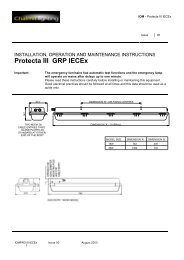
3.5 Mounting<br />
Luminaires should be installed where access for maintenance is practical and in accordance with any lighting<br />
design information provided for the installation. This will usually consist of aiming points and aiming angles. The<br />
foot mounting or rear mounting arrangements should be secured with lock washers or self-locking nuts and bolts.<br />
The luminaire should be mounted with the lamp axis horizontal.<br />
3.5.1 Weights and Windages<br />
Note : Weights and Windages for the various types are outlined in Table 4.<br />
3.6 Cabling and Cable Glands<br />
3.6.1 Cables<br />
The cable entry temperatures are given as the rise over the maximum rated ambient temperature. This allows<br />
the user to adjust the cable specification for actual site maximum temperature. The standard conductor section<br />
is 6mm² max. All models are suitable for looping except the 400W remote gear version. Standard 300/500V<br />
cable is suitable. The cable makeup must be suitable to ensure the obtaining of a restricted breathing enclosure<br />
when the cable gland assembly is fitted.<br />
3.6.2 Cable Glands<br />
Cable glands and sealing plugs when installed must maintain the restricted breathing enclosure. (Vacuum test;<br />
300mm head of water, half pressure time 3 mins. minimum). Rubber sealing washers and steel compression<br />
washers are provided with the unit to seal between the gland body and the luminaire. The body torque value is<br />
12Nm. The user must ensure that the assembly fulfils the above requirement. No means of checking the air<br />
tightness of the assembled unit is provided. When new sealing arrangements are to be installed, users should<br />
check a sample for substantial air tightness before making a full installation. Entries suitable for M20 cable<br />
glands are standard. Entries suitable for M25 are available to special order.<br />
<strong>IOM</strong>MAX IECEx Issue 00 August 03 3