Sanitary Sewer Pipe - City and Borough of Juneau
Sanitary Sewer Pipe - City and Borough of Juneau
Sanitary Sewer Pipe - City and Borough of Juneau

Create successful ePaper yourself
Turn your PDF publications into a flip-book with our unique Google optimized e-Paper software.
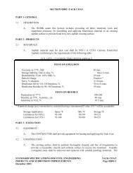
SECTION 02401 - SANITARY SEWER PIPE<br />
PART 1 - GENERAL<br />
1.1 DESCRIPTION<br />
A. The WORK under this Section includes providing all labor, materials, tools <strong>and</strong><br />
equipment necessary for furnishing <strong>and</strong> installing sanitary sewer pipe, in accordance with<br />
these Specifications <strong>and</strong> in reasonably close conformity with the lines <strong>and</strong> grades shown<br />
on the Drawings or established by the ENGINEER.<br />
B. This WORK includes furnishings <strong>and</strong> installing connecting b<strong>and</strong>s, branch connections,<br />
elbows or other fittings, <strong>and</strong> all appurtenances required to complete the sanitary sewer.<br />
1.2 SUBMITTALS<br />
A. <strong>Sanitary</strong> <strong>Sewer</strong> <strong>Pipe</strong>: Material certifications stating conformance with the requirements <strong>of</strong><br />
this Section.<br />
PART 2 - PRODUCTS<br />
2.1 DUCTILE IRON PIPE (GRAVITY AND PRESSURE SEWER)<br />
A. Ductile Iron <strong>Pipe</strong> shall conform to ANSI A21.51. <strong>Pipe</strong> <strong>and</strong> fittings shall be cement<br />
mortar lined in conformance with ANSI A21.4 <strong>and</strong> shall have an exterior bituminous<br />
coating conforming to the requirements <strong>of</strong> ANSI A21.10. <strong>Pipe</strong> joints shall conform to<br />
ANSI A2.11 <strong>and</strong> shall be push-on type as manufactured by United States <strong>Pipe</strong> <strong>and</strong><br />
Foundry Company for Tyton pipe, or equal.<br />
B. Prior to the use <strong>of</strong> any pipe, the CONTRACTOR shall furnish a certification from the<br />
pipe manufacturer that all required tests have been made <strong>and</strong> that the pipe fully complies<br />
with the requirements <strong>of</strong> ANSI A21.51.<br />
C. Nominal pipe diameter is shown on the Drawings. No change in pipe diameter shall be<br />
made unless approved by the ENGINEER. The minimum pipe strength shall be<br />
thickness Class 50. The pipe size <strong>and</strong> thickness class shall be clearly marked on each<br />
pipe.<br />
D. Where special fittings are required, they shall be fabricated from steel pipe manufactured<br />
in accordance with AWWA St<strong>and</strong>ard C200. The steel fitting shall be fabricated with<br />
spigot ends suitable for connection to the ductile iron pipe, with cast iron transition<br />
couplings as manufactured by Smith-Blair, Inc., or equal. Steel fittings shall be lined <strong>and</strong><br />
coated with fusion epoxy system as supplied by Water Works Supply Company, Union<br />
<strong>City</strong>, California, or with hot applied coal tar in accordance with AWWA C203.<br />
E. Connections between ductile iron pipe <strong>and</strong> PVC pipe shall be made with 'ROMAC"<br />
Stainless Steel Sleeve, or approved equal.<br />
STANDARD SPECIFICATIONS FOR CIVIL ENGINEERING SANITARY SEWER PIPE<br />
PROJECTS AND SUBDIVISION IMPROVEMENTS Page 02401-1<br />
December 2003
SECTION 02401 - SANITARY SEWER PIPE<br />
2.2 PVC SEWER PIPE<br />
A. PVC <strong>Sewer</strong> <strong>Pipe</strong>, four inch through 15 inch in diameter, inclusive, shall have a st<strong>and</strong>ard<br />
dimension ratio (SDR) <strong>of</strong> 35, <strong>and</strong> conform to ASTM D 3034. Before any PVC pipe is<br />
used on this Project, the CONTRACTOR shall supply certifications, signed by an<br />
authorized agent <strong>of</strong> the seller or manufacturer, stating that the material has been sampled,<br />
tested, <strong>and</strong> inspected in accordance with ASTM D 3034.<br />
B. PVC <strong>Sewer</strong> <strong>Pipe</strong> greater than 15 inch in diameter shall conform to ASTM F 679. Before<br />
any PVC pipe is used, the CONTRACTOR shall supply certifications, signed by an<br />
authorized agent <strong>of</strong> the seller or manufacturer, stating that the material has been sampled,<br />
tested, <strong>and</strong> inspected in accordance with ASTM F 679.<br />
C. The pipe shall have integral wall bell <strong>and</strong> spigot joints conforming to ASTM D 3212.<br />
The bell shall consist <strong>of</strong> an integral wall section with a solid cross-section elastomeric<br />
ring, factory assembled, securely locked in place to prevent displacement.<br />
D. Flexible water-tight connections, approved by the ENGINEER, shall be used at PVC pipe<br />
connections to manholes <strong>and</strong> other rigid structures.<br />
2.3 PVC PRESSURE PIPE<br />
A. PVC pressure pipe shall conform to the applicable requirements <strong>of</strong> ANSI/AWWA C900<br />
<strong>and</strong> subject to additional requirements specified herein.<br />
B. The pipe shall be pressure class 100, <strong>and</strong> shall be furnished complete with rubber gaskets.<br />
C. Fittings for PVC pressure pipe shall be cement motor lined ductile iron in conformance<br />
with ANSI A21.4 <strong>and</strong> shall have an exterior bituminous coating conforming to the<br />
requirements <strong>of</strong> ANSI A21.10.<br />
D. All joints for the buried PVC pipe shall be either an integral bell manufactured on the<br />
pipe or a separate coupling both employing a rubber ring joint. The bell <strong>and</strong> coupling<br />
shall be the same thickness as <strong>of</strong> the pipe barrel, or greater thickness. The sealing ring<br />
groove in the coupling shall be <strong>of</strong> the same design as the groove in cast iron fittings <strong>and</strong><br />
valves available from local water works supply distributors.<br />
E. Flexible water-tight connections, approved by the ENGINEER, shall be used at PVC<br />
connections to manholes <strong>and</strong> other rigid structures.<br />
F. Connections between PVC <strong>Sewer</strong> <strong>Pipe</strong> <strong>and</strong> PVC Pressure <strong>Pipe</strong> (PVC (HP)), shall be<br />
made with "ROMAC" Stainless Steel Sleeve, or approved equal.<br />
2.4 HDPE PRESSURE PIPE<br />
A. High-Density Polyethylene (HDPE) pipe shall conform to ASTM D 3550 designation PE<br />
3407 or PE 3408. The pipe shall have a minimum pressure rating <strong>of</strong> 100 pounds per<br />
square inch <strong>and</strong> a maximum St<strong>and</strong>ard Dimension Ration (SDR) <strong>of</strong> 17.0. All HDPE shall<br />
have a st<strong>and</strong>ard iron pipe size (IPS) outside diameter.<br />
STANDARD SPECIFICATIONS FOR CIVIL ENGINEERING SANITARY SEWER PIPE<br />
PROJECTS AND SUBDIVISION IMPROVEMENTS Page 02401-2<br />
December 2003
SECTION 02401 - SANITARY SEWER PIPE<br />
B. The pipe shall be homogeneous throughout <strong>and</strong> free <strong>of</strong> visible cracks, holes, foreign<br />
inclusions or other injurious defects. It shall be uniform in color, opacity, density, <strong>and</strong><br />
other physical properties.<br />
C. HDPE pipe shall have an ASTM D-3350 material Cell Classification <strong>of</strong> no less than<br />
335434C.<br />
D. The pipe shall be marked at five foot intervals with a coded number which identifies the<br />
manufacturer, SDR size, PPI rating, manufacturing st<strong>and</strong>ard reference <strong>and</strong> production<br />
code from which data <strong>and</strong> place <strong>of</strong> manufacturer can be determined.<br />
E. When HDPE pipe is connected to ductile iron pipe, a flange adapter shall be used. A<br />
flange-coupling adapter shall be used on the ductile iron pipe. HDPE flange adapters<br />
shall be manufactured by the same manufacturer as the pipe using the same resin as the<br />
pipe. Each flange adapter shall be furnished with a ductile iron convoluted back-up ring<br />
drilled to match the st<strong>and</strong>ard ANSI bolt pattern for the nominal diameter <strong>of</strong> pipe used.<br />
F. Connection <strong>of</strong> the pipe <strong>and</strong> fittings shall be performed by the thermal butt fusion system.<br />
HDPE pipe lengths, fittings, <strong>and</strong> flange adapter connections to be fused shall be <strong>of</strong> the<br />
same type, grade <strong>and</strong> class <strong>of</strong> polyethylene compound <strong>and</strong> supplied by the same raw<br />
material supplier.<br />
2.5 PVC PRESSURE PIPE WITH RESTRAINED JOINTS<br />
A. Piping for PVC Pressure <strong>Pipe</strong> with Restrained Joints shall be PVC Pressure <strong>Pipe</strong> as<br />
specified above.<br />
B. <strong>Pipe</strong> joints shall be restrained using Uniflange Series 1350 joint restraints or approved<br />
equal.<br />
2.6 POLYETHYLENE PIPE<br />
A. Polyethylene <strong>Pipe</strong> shall conform to the requirements <strong>of</strong> ASTM F 714, with SDR <strong>of</strong> 32.5.<br />
B. <strong>Pipe</strong> shall be listed by the National Sanitation Foundation.<br />
C. Joints shall be made by butt-fusion, with connections to dissimilar materials by stub ends<br />
<strong>and</strong> backing flanges or steel/HDPE transition couplings.<br />
2.7 ACRYLONITRILE-BUTADIENE-STYRENE (ABS) PIPE<br />
A. Acrylonitrile-Butadiene-Styrene (ABS) <strong>Pipe</strong> four inches in diameter shall conform to the<br />
requirements <strong>of</strong> ASTM D 2751. ABS <strong>Pipe</strong> six inches through 15 inches in diameter shall<br />
conform to the requirements <strong>of</strong> AASHTO M 264 (ASTM D 2680).<br />
B. Joints shall be solvent welded using a primer <strong>and</strong> cement in accordance with the<br />
manufacturer's specifications. All joints shall be wiped clean <strong>and</strong> dry before applying the<br />
primer. All fittings shall be installed in accordance with the manufacturer's<br />
specifications.<br />
STANDARD SPECIFICATIONS FOR CIVIL ENGINEERING SANITARY SEWER PIPE<br />
PROJECTS AND SUBDIVISION IMPROVEMENTS Page 02401-3<br />
December 2003
SECTION 02401 - SANITARY SEWER PIPE<br />
C. H<strong>and</strong>ling, storage, <strong>and</strong> installation <strong>of</strong> pipe shall conform to the recommendations <strong>of</strong> the<br />
manufacturer.<br />
D. Truss pipe shall be used only with Fiberglass Reinforced Plastic (FRP) manholes using<br />
molded truss pipe connectors bonded to the barrel.<br />
2.8 UNDERGROUND MARKING TAPE<br />
A. Underground marking tape shall be green, at least four (4) inches wide, four mil thick,<br />
polyethylene tape, with a metallic backing capable <strong>of</strong> being traced with locators. The<br />
tape shall have black letters with the following wording: "Caution: <strong>Sewer</strong> Line Buried<br />
Below." The marking tape shall be installed 12 inches above the top <strong>of</strong> all sewer mains<br />
<strong>and</strong> services.<br />
PART 3 - EXECUTION<br />
3.1 CONSTRUCTION<br />
A. Excavation, bedding, <strong>and</strong> backfill shall conform to the requirements <strong>of</strong> Section 02203 -<br />
Trenching. Underground marking tape shall be installed as shown on CBJ St<strong>and</strong>ard<br />
Detail 125 - Pavement Resurfacing <strong>and</strong> Trench Detail.<br />
B. Sheeting <strong>and</strong> bracing required for trenches shall be removed to the elevation <strong>of</strong> the<br />
conduit, but no sheeting will be allowed to be pulled, removed, or disturbed below the<br />
conduit. Sheeting <strong>and</strong> bracing shall meet OSHA requirements.<br />
C. Before lowering into the trench, the pipe shall be inspected for defects. All cracked,<br />
chipped, or broken pipe shall be discarded. The ends <strong>and</strong> interior <strong>of</strong> the pipe shall be<br />
clean. Belled ends shall be laid upgrade. H<strong>and</strong>ling <strong>of</strong> the pipe shall be accomplished in a<br />
manner that will not damage the pipe. The joint shall be made in the manner<br />
recommended by the manufacturer. Care shall be taken not to buckle or disturb<br />
previously laid pipe.<br />
D. <strong>Pipe</strong> shall be laid accurately to the staked line <strong>and</strong> grade. All service connections shall be<br />
installed as indicated on the Drawings. Where existing service sewers are to be<br />
connected, suitable fittings <strong>and</strong> adapters shall be provided by the CONTRACTOR.<br />
E. <strong>Pipe</strong> shall be cleaned <strong>of</strong> all foreign matter, <strong>and</strong> water shall be kept out <strong>of</strong> trenches until<br />
joints have been completed. When WORK is not in progress, open ends <strong>of</strong> pipe <strong>and</strong><br />
fittings shall be securely closed to keep foreign matter <strong>and</strong> animals from entering.<br />
F. Each joint shall be inspected to ensure that it is properly made before backfilling is done.<br />
Care shall be taken to prevent any dirt or foreign matter from entering the open end <strong>of</strong> the<br />
pipe. Where it is necessary to cut pipe, such cuts shall be neatly made in an approved<br />
manner. The laid pipe shall be true to line <strong>and</strong> grade <strong>and</strong>, when completed, the sewer<br />
shall have a smooth <strong>and</strong> uniform invert. No section <strong>of</strong> gravity sewer, including service<br />
connections shall have an adverse grade which would pond water in the invert <strong>of</strong> the<br />
sewer.<br />
STANDARD SPECIFICATIONS FOR CIVIL ENGINEERING SANITARY SEWER PIPE<br />
PROJECTS AND SUBDIVISION IMPROVEMENTS Page 02401-4<br />
December 2003
SECTION 02401 - SANITARY SEWER PIPE<br />
G. Connections to pipe stubs <strong>of</strong> a different pipe material shall be made with DFW/HPI nonshear-type<br />
connector, as shown in CBJ St<strong>and</strong>ard Detail 218 - Coupling for Dissimilar<br />
<strong>Sanitary</strong> <strong>Sewer</strong> <strong>Pipe</strong>s. Connectors must be approved by the ENGINEER prior to<br />
installation.<br />
H. Connections to pipe stubs <strong>of</strong> a different pipe material, if made beyond the back <strong>of</strong><br />
sidewalk or other concrete or paved surface, shall be made with a suitable connector.<br />
Connectors must be approved by the ENGINEER prior to installation. Connection <strong>of</strong> all<br />
piping, other than bell <strong>and</strong> spigot connections, within the roadway, street <strong>and</strong> sidewalk<br />
areas, shall be made per CBJ St<strong>and</strong>ard Detail 218 - Coupling for Dissimilar <strong>Sanitary</strong><br />
<strong>Sewer</strong> <strong>Pipe</strong>s.<br />
I. Connections to existing sewer mains, service connections, <strong>and</strong> manholes shall be made in<br />
such a manner so as to not damage the existing facility. Such connections shall be made<br />
so that no projections or rough surfaces occur within the pipe.<br />
J. Locations <strong>of</strong> the sewer laterals are approximate <strong>and</strong> may be changed by the ENGINEER.<br />
Relocating <strong>of</strong> the sewer lateral will not add extra cost to the OWNER, unless either <strong>of</strong> the<br />
following conditions result:<br />
1. The relocation results in a significant increase in the length <strong>of</strong> the lateral; or,<br />
2. There are significant differences in the surface characteristics at the new lateral<br />
location which would result in substantial <strong>and</strong> foreseeable changes in<br />
construction methods <strong>and</strong> materials.<br />
K. If the CONTRACTOR believes that the WORK at the new location(s) will result in a<br />
substantive change, the CONTRACTOR shall notify the ENGINEER prior to beginning<br />
the changed WORK. The ENGINEER will evaluate the request <strong>and</strong> if the relocation is<br />
warranted, the change in WORK shall be authorized.<br />
L. Lateral connections to existing sewer mains shall not obstruct flow <strong>and</strong> shall be one <strong>of</strong><br />
the following:<br />
1. Approved remote tapping system<br />
2. Polyethylene saddle strapped to line with two stainless steel b<strong>and</strong>s <strong>and</strong> neoprene<br />
gaskets.<br />
3. Sidewall fused to line as recommended by pipe manufacturer.<br />
4. Manufactured saddle per CBJ St<strong>and</strong>ard Detail 210 - <strong>Sanitary</strong> <strong>Sewer</strong> Saddle Tee.<br />
M. Cleanouts shall be provided with a cast iron ring <strong>and</strong> cover which shall be locking-type<br />
Olympic Foundry No. M-1025, or approved equal. The cover shall be clearly marked<br />
with the word "SEWER" case into it.<br />
N. Lateral connections to new sewer mains shall be made with a manufactured sanitary wye<br />
<strong>of</strong> the same material as the mainline pipe.<br />
O. Locate <strong>Sewer</strong> Services shall require that the CONTRACTOR determine the location <strong>of</strong><br />
the existing sewer services prior to installation <strong>of</strong> the mainline pipe in such a way that the<br />
STANDARD SPECIFICATIONS FOR CIVIL ENGINEERING SANITARY SEWER PIPE<br />
PROJECTS AND SUBDIVISION IMPROVEMENTS Page 02401-5<br />
December 2003
SECTION 02401 - SANITARY SEWER PIPE<br />
service wyes can be installed in the proper location as the mainline pipe is being installed.<br />
No service saddles will be permitted, unless approved by the ENGINEER.<br />
P. Where gravity flow sanitary sewers cross above or less than 18 inches below waterlines,<br />
or approximately parallel water lines within ten feet horizontally, the sewer pipe shall<br />
meet the requirements <strong>of</strong> ductile iron pipe or PVC pressure pipe, as described in Part 2 <strong>of</strong><br />
this Section.<br />
Q. HDPE to HDPE connections shall be made by thermal butt fusion, in accordance with<br />
ASTM D2657. Fusion jointing shall utilize a pipe manufacturer approved fusion<br />
machine operated by experienced <strong>and</strong> qualified personnel. The CONTRACTOR shall<br />
provide three copies <strong>of</strong> a "Heat Fusion Qualification Guide," published by the HDPE<br />
manufacturer, that provides criteria for inspection <strong>of</strong> thermal fusion joints. The guide<br />
shall include criteria for operator training requirements <strong>and</strong> experience; visual inspection<br />
criteria (including photographs) for both intact thermal fusion joints <strong>and</strong> sample strips cut<br />
for thermal fusion joints. The thermal fusion machine operator shall perform a minimum<br />
<strong>of</strong> three test joints in the presence <strong>of</strong> the ENGINEER. The test joints will be examined<br />
from both exterior appearances <strong>and</strong> from appearance <strong>of</strong> the joint cross section once the<br />
samples have been cut into strips.<br />
R. Bolted HDPE to HDPE connections shall include a polyethylene flange adapter (stub<br />
end) butt fused to the pipe, a backup flange ring, bolts, nuts <strong>and</strong> a gasket. Flange rings<br />
shall be St<strong>and</strong>ard Steel ring Flanges, Class D, in accordance with AWWA C207. High<br />
strength bolts, nuts, washers <strong>and</strong> gaskets shall be in conformance with AWWA C207,<br />
Appendix A. Flange rings, bolts, nuts <strong>and</strong> washers shall be hot dip galvanized after<br />
fabrication per ASTM A153 <strong>and</strong> A386. Gasket dimensions <strong>and</strong> bolt lengths shall be per<br />
pipe manufacturer's recommendations.<br />
3.2 TESTING<br />
A. Prior to testing all manholes, all sections <strong>of</strong> pipe shall be cleaned using an inflatable<br />
rubber ball <strong>of</strong> a size that will inflate to fit snugly into the pipe. The ball may, at the<br />
option <strong>of</strong> the CONTRACTOR, be used without a tag line; or a rope or cord may be<br />
fastened to the ball to enable the CONTRACTOR to know <strong>and</strong> control its position at all<br />
times. The ball shall be placed in the last clean out or manhole on the pipe to be cleaned,<br />
<strong>and</strong> water shall be introduced behind it. The ball shall pass through the pipe with only<br />
the force <strong>of</strong> the water impelling it. All debris flushed out ahead <strong>of</strong> the ball shall be<br />
removed at the first manhole where its presence is noted. In the event cemented or<br />
wedged debris, or a damaged pipe, stops the ball, the CONTRACTOR shall remove the<br />
obstruction <strong>and</strong> make any necessary repairs in a manner that is acceptable to the<br />
ENGINEER. Any alternate methods <strong>of</strong> cleaning sewers shall be submitted to the<br />
ENGINEER for approval, <strong>and</strong> shall not be used unless approved.<br />
B. Prior to testing, the sewer shall be complete with laterals, <strong>and</strong> trenches shall be fully<br />
backfilled <strong>and</strong> compacted to finish grade, or, if the sewer is under pavement, finish<br />
pavement subgrade.<br />
C. For WORK involving placement <strong>of</strong> new sanitary sewer collection systems, all sections <strong>of</strong><br />
pipe shall be tested for leakage using the Exfiltration Test for either air or water as<br />
specified hereafter; or, at the sole direction <strong>of</strong> the ENGINEER, when the normal water<br />
STANDARD SPECIFICATIONS FOR CIVIL ENGINEERING SANITARY SEWER PIPE<br />
PROJECTS AND SUBDIVISION IMPROVEMENTS Page 02401-6<br />
December 2003
SECTION 02401 - SANITARY SEWER PIPE<br />
table is above the sewer throughout the section under test, the ENGINEER may permit<br />
use <strong>of</strong> the Infiltration Test procedure specified hereafter. Where leakage is in excess <strong>of</strong><br />
the specified rate, the sewer shall be repaired by the CONTRACTOR as required to<br />
comply with the leakage test requirements. The ENGINEER may require the<br />
CONTRACTOR to repair obvious leaks even though the total length <strong>of</strong> the test section<br />
falls within the maximum allowable leakage for the test used.<br />
D. For WORK involving replacement <strong>of</strong> existing, active sanitary sewer collection systems,<br />
<strong>and</strong> the new system is not put into service during the same work shift, no Exfiltration/ or<br />
Infiltration Tests will be required. TV inspection <strong>of</strong> the new pipes by the ENGINEER<br />
shall be used to determine system acceptance.<br />
E. Defective pipe joints shall be repaired in a manner that the repaired pipe joint will have<br />
some flexibility <strong>and</strong> the effectiveness <strong>of</strong> the repair will not be affected by differential<br />
movement <strong>of</strong> the adjoining pipes. A "CSSI" or DFW/HPI non-shear coupling, as per<br />
CBJ St<strong>and</strong>ard Detail 218 - Coupling for Dissimilar <strong>Sanitary</strong> <strong>Sewer</strong> <strong>Pipe</strong>s, or approved<br />
equal, will be acceptable in making such repairs.<br />
F. The ENGINEER will make one complete TV inspection after all sewers have passed the<br />
specified watertightness test. All defects regarding sewer alignment <strong>and</strong> grade, damaged<br />
pipe, <strong>and</strong> visible leaks observed during this inspection, shall be corrected by the<br />
CONTRACTOR. The CONTRACTOR shall de-water the sewers as required for the<br />
performance <strong>of</strong> the TV inspection work by the ENGINEER. The CONTRACTOR shall<br />
be responsible for all costs associated with any TV inspection required following the<br />
initial TV inspection, if any defects were observed during this or any subsequent TV<br />
inspections.<br />
G. The hydrostatic test procedure for HDPE <strong>Pipe</strong> shall consist <strong>of</strong> two (2) steps: the initial<br />
expansion phase <strong>and</strong> the test period. In order to accommodate the initial expansion <strong>of</strong> the<br />
pipe under test, sufficient make-up water shall be added to the system at hourly intervals<br />
for three hours to return to the test pressure. The test period begins after the final<br />
addition <strong>of</strong> make-up water in the expansion phase <strong>of</strong> the test procedure. The test period<br />
is three (3) hours. After this test period, a measured amount <strong>of</strong> make-up water shall be<br />
added to return to test pressure. The amount <strong>of</strong> make-up water shall not exceed the<br />
allowable expansion in U.S. gallons shown in the following table:<br />
THREE HOUR TEST<br />
Nominal <strong>Pipe</strong> Size<br />
(Inches)<br />
Allowance for Expansion<br />
(U.S. Gal. Per 100 feet <strong>of</strong><br />
pipe)<br />
8 1.5<br />
10 2.1<br />
12 3.4<br />
16 5.0<br />
18 6.5<br />
STANDARD SPECIFICATIONS FOR CIVIL ENGINEERING SANITARY SEWER PIPE<br />
PROJECTS AND SUBDIVISION IMPROVEMENTS Page 02401-7<br />
December 2003
SECTION 02401 - SANITARY SEWER PIPE<br />
Under no circumstances shall the total test procedure exceed eight hours at 1.5 times the<br />
pipe pressure rating. If the test is not completed within eight hours, the test section shall<br />
not be re-tested for eight more hours. Repair <strong>and</strong> re-testing shall continue until a passing<br />
test is obtained.<br />
3.3 FILTRATION TEST (USING AIR)<br />
A. The CONTRACTOR shall furnish all facilities <strong>and</strong> personnel for conducting the test<br />
under the observation <strong>of</strong> the ENGINEER. The equipment <strong>and</strong> personnel shall be subject<br />
to the approval <strong>of</strong> the ENGINEER. Joints only may be tested in pipe 36 inches in<br />
diameter or larger, at the option <strong>of</strong> the CONTRACTOR.<br />
B. Immediately following the pipe cleaning, the pipe installation shall be tested with low<br />
pressure air. Air shall be slowly supplied to the plugged pipe installation until the<br />
internal air pressure reaches five pounds per square inch greater than the average back<br />
pressure <strong>of</strong> any ground water that may submerge the pipe. At least two minutes shall be<br />
allowed for temperature stabilization before proceeding further.<br />
C. The pipeline shall be considered acceptable when tested at an average pressure <strong>of</strong> four psi<br />
greater than the average pressure <strong>of</strong> any ground water that may submerge the pipe if the<br />
section under test does not lose air at a rate greater than 0.0030 cubic feet per minute per<br />
square foot <strong>of</strong> internal surface.<br />
D. The requirements <strong>of</strong> this Specification shall be considered satisfied if the time required<br />
for the pressure to decrease from 4.5 psi to 3.5 psi above average ground water pressure<br />
is greater than that shown on the following table:<br />
TIME FOR PRESSURE TO DROP FROM<br />
4.5 TO 3.5 PSI ABOVE AVERAGE GROUND WATER PRESSURE<br />
<strong>Pipe</strong> Diameter Minutes Seconds<br />
8 " 3 57<br />
10" 4 43<br />
12" 5 40<br />
15" 7 5<br />
18" 8 30<br />
24" 11 20<br />
30" 14 10<br />
E. For other sizes, determine test time using the following formula:<br />
T= 28.33 D<br />
Where T = time in seconds<br />
D = pipe diameter in inches<br />
F. For pipes 36 inches in diameter, or larger, if individual joints are tested, they shall hold<br />
six psi air pressure over the average back pressure <strong>of</strong> any ground water for a minimum<br />
time <strong>of</strong> 15 seconds.<br />
STANDARD SPECIFICATIONS FOR CIVIL ENGINEERING SANITARY SEWER PIPE<br />
PROJECTS AND SUBDIVISION IMPROVEMENTS Page 02401-8<br />
December 2003
SECTION 02401 - SANITARY SEWER PIPE<br />
G. Pressure gauges should be incremented in not more than one-half pound increments for<br />
accurate tests.<br />
H. Braces shall be required to hold plugs in place <strong>and</strong> to prevent the sudden release <strong>of</strong> the<br />
compressed air. Due to the large forces that could be exerted by an escaping plug during<br />
the testing <strong>of</strong> the pipe, no one shall be allowed in the manholes in which plugs have been<br />
placed while tests are being conducted. The CONTRACTOR's testing equipment shall<br />
have a pressure relief device that will prohibit the pressure in the pipeline from exceeding<br />
ten pounds per square inch.<br />
3.4 EXFILTRATION TEST (USING WATER)<br />
A. Where groundwater is below the pipe to be tested, a minimum <strong>of</strong> head <strong>of</strong> eight feet <strong>of</strong><br />
water above the crown at the upper end <strong>of</strong> the test section shall be maintained for a period<br />
<strong>of</strong> four hours, during which time it will be presumed that full absorption <strong>of</strong> the pipe body<br />
has taken place, <strong>and</strong> thereafter for a further period <strong>of</strong> one hour for the actual test <strong>of</strong><br />
leakage. During this one hour period, the measured loss shall not exceed the rate given<br />
below:<br />
Type <strong>of</strong> <strong>Pipe</strong><br />
PVC<br />
Ductile Iron<br />
Allowable Exfiltration Rate<br />
E = 0.0004 DL<br />
E = 0.00008 DL<br />
E = Allowable leakage in gallons per hour<br />
D = Nominal inside diameter <strong>of</strong> pipe in inches<br />
L = Length <strong>of</strong> pipe being tested in feet<br />
B. Where groundwater is above any pipe to be tested, the minimum head <strong>of</strong> the test will be<br />
raised to provide an elevation head <strong>of</strong> eight feet above the groundwater.<br />
C. The maximum length <strong>of</strong> sewer in any test section shall be 500 feet.<br />
3.5 INFILTRATION TEST<br />
A. Infiltration testing may be allowed at the ENGINEER's option when the natural ground<br />
water table is above the crown <strong>of</strong> the higher end <strong>of</strong> the test section <strong>and</strong> the external water<br />
pressure exerted on the pipe is equivalent to the exfiltration test. The maximum<br />
allowable limit for infiltration shall be as determined by the formulas defined in the<br />
above section Exfiltration Test (Using Water).<br />
3.6 PRESSURE SEWER TEST<br />
A. The CONTRACTOR shall, in the presence <strong>of</strong> the ENGINEER, test all pressure sewer<br />
pipe to a test pressure <strong>of</strong> 100 pounds per square inch <strong>and</strong> maintain the pressure a<br />
minimum <strong>of</strong> one hour. The CONTRACTOR shall make all necessary arrangements to<br />
provide water for testing pipelines.<br />
STANDARD SPECIFICATIONS FOR CIVIL ENGINEERING SANITARY SEWER PIPE<br />
PROJECTS AND SUBDIVISION IMPROVEMENTS Page 02401-9<br />
December 2003
SECTION 02401 - SANITARY SEWER PIPE<br />
B. Leakage shall not be in excess <strong>of</strong> five gallons per inch <strong>of</strong> pipe diameter per one thous<strong>and</strong><br />
(1,000) feet <strong>of</strong> pipe per day. Where leakage is in excess <strong>of</strong> the specified rate, the<br />
CONTRACTOR shall make all repairs necessary to reduce the amount <strong>of</strong> leakage to a<br />
quantity within the specified rate. The testing <strong>and</strong> repair process shall be repeated until<br />
the installation is accepted. In addition, the CONTRACTOR shall repair all visible leaks.<br />
END OF SECTION<br />
STANDARD SPECIFICATIONS FOR CIVIL ENGINEERING SANITARY SEWER PIPE<br />
PROJECTS AND SUBDIVISION IMPROVEMENTS Page 02401-10<br />
December 2003