AZB 800 - Junkers
AZB 800 - Junkers
AZB 800 - Junkers

Create successful ePaper yourself
Turn your PDF publications into a flip-book with our unique Google optimized e-Paper software.
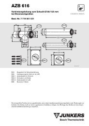
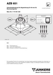
<strong>AZB</strong> <strong>800</strong><br />
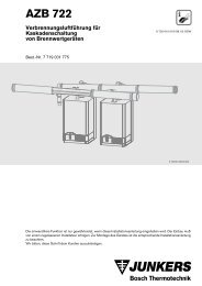
Vertical Flue Gas Ducting<br />
Ø60/100mm<br />
7 719 001 884<br />
Ø120<br />
1310<br />
535<br />
Ø98.5<br />
Ø125<br />
50<br />
125<br />
6 720 610 703-00.1O<br />
for Gas Condensing Boilers:<br />
ZWB 7-29 CC1<br />
ZB 7-28 CS1<br />
ZSBR 7-28 ICS1<br />
ZWBR 8-30 ICC2<br />
ZBR 8-35 ICS1<br />
ZWBR 11-37 ICC2<br />
ZWB 7-27 HE combi<br />
ZB 7-27 HE system<br />
ZWBR 7-28 HE plus<br />
ZWBR 11-35 HE plus<br />
6 720 610 703 (01.07) OSW
Contents<br />
Contents<br />
Safety instructions 2<br />
Symbols 2<br />
1 Use 3<br />
1.1 General 3<br />
1.2 Gas condensing boilers 3<br />
1.3 Combination with flue duct kits 3<br />
1.4 Standard specifications 3<br />
2 Fitting space requirements for gas<br />
condensing boiler 4<br />
3 Examples of installation of vertical flue duct<br />
with roof exit 5<br />
3.1 Straight flue ducting without elbows 5<br />
3.2 Straight flue ducting with two 45°-elbows 5<br />
3.3 Straight flue ducting with two 90°-elbows 6<br />
3.4 Flue ducting with more than two elbows 7<br />
4 Mounting 8<br />
4.1 Notes on fitting 8<br />
4.2 Roof-exit clearances 8<br />
4.3 Fitting the flue ducting 9<br />
Safety instructions<br />
Proper functioning of this product is only guaranteed if<br />
these installation instructions are correctly followed.<br />
Subject to alteration. Installation must be carried out by<br />
an approved installer. Installation of the boiler must be<br />
carried out in accordance with the appropriate installation<br />
instructions.<br />
If you smell fumes from the appliance<br />
B Switch off appliance.<br />
B Open windows and doors.<br />
B Inform your heating engineer.<br />
Fitting and modifications<br />
B Fitting of the appliance or any controls to the appliance<br />
may only be carried out by a competent engineer<br />
in accordance with the Gas Safety (Installation<br />
and Use) Regulations 1998.<br />
B Flue systems must not be modified in any ways other<br />
than as described in the fitting instructions.<br />
Symbols<br />
i<br />
Notes are identified by the symbol shown<br />
on the left. They are bordered by horizontal<br />
lines above and below the text.<br />
2<br />
6 720 610 703 (01.07)
Use<br />
1 Use<br />
1.1 General<br />
1.4 Standard specifications<br />
The installation of a gas condensing boiler must be in<br />
accordance with the relevant British Standard, the relevant<br />
Building Regulations and any local rules.<br />
The surface temperature of the fresh air duct is below<br />
85°C. Therefore no minimum distances to combustible<br />
building materials are necessary. The regulations can<br />
deviate, however, and might prescribe minimum distances<br />
to combustible materials.<br />
The flue gas accessory is part of CE approval when discharging<br />
flue gas. For this reason, only the original flue<br />
gas accessories may be used.<br />
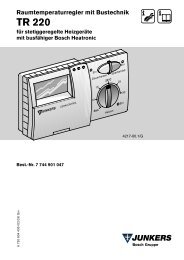
1.2 Gas condensing boilers<br />
B4<br />
120<br />
535<br />
1310<br />
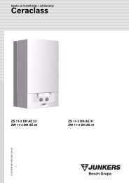
The <strong>AZB</strong> <strong>800</strong> can be used in conjunction with the following<br />
gas condensing boilers:<br />
Gas condensing boilers<br />
ZWB 7-29 CC1<br />
ZB 7-28 CS1<br />
Prod.-ID-No.<br />
Ø98.5<br />
ZSBR 7-28 ICS1<br />
ZWBR 8-30 ICC2<br />
B4.1<br />
Ø125<br />
50<br />
125<br />
ZBR 8-35 ICS1<br />
ZWBR 11-37 ICC2<br />
ZWB 7-27 HE combi<br />
ZB 7-27 HE system<br />
ZWBR 7-28 HE plus<br />
ZWBR 11-35 HE plus<br />
Table 1<br />
CE 0085 BL 0507<br />
Fig. 1<br />
6 720 610 703-01.1O<br />
B4: Vertical Flue Gas Ducting <strong>AZB</strong> <strong>800</strong><br />
B4.1: Adapter Ø 80/125 - Ø 60/100<br />
1.3 Combination with flue duct kits<br />
The <strong>AZB</strong> <strong>800</strong> can be combined with the following flue<br />
duct kits:<br />
Flue duct kits<br />
<strong>AZB</strong> 802, elbow 90°<br />
<strong>AZB</strong> 803, elbow 45°<br />
<strong>AZB</strong> 804, extension 1000 mm<br />
Table 2<br />
6 720 610 703 (01.07)<br />
3
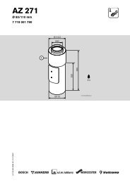
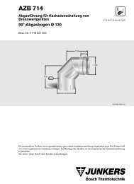
Fitting space requirements for gas condensing boiler<br />
2 Fitting space requirements for gas condensing boiler<br />
B C B C<br />
ZWB 7-29 CC1<br />
ZB 7-28 CS1<br />
ZWB 7-27 HE combi<br />
ZB 7-27 HE system<br />
440 mm ≥ 5 mm<br />
ZSBR 7-28 ICS1<br />
ZWBR 8-30 ICC2<br />
ZBR 8-35 ICS1<br />
ZWBR 11-37 ICC2<br />
ZWBR 7-28 HE plus<br />
ZWBR 11-35 HE plus<br />
512 mm ≥ 100 mm<br />
Table 3<br />
C<br />
98.5<br />
C<br />
850<br />
77 ≥ 1150<br />
360<br />
85<br />
120<br />
B<br />
≥ 835<br />
6 720 610 703-02.1O<br />
Fig. 2<br />
Flat roof<br />
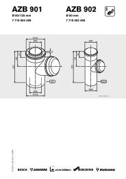
≥ 835<br />
C<br />
98.5<br />
C<br />
≥ 957<br />
85<br />
120<br />
850<br />
360<br />
77<br />
B<br />
6 720 610 703-03.1O<br />
Fig. 3<br />
Inclined roof<br />
4<br />
6 720 610 703 (01.07)
Examples of installation of vertical flue duct with roof exit<br />
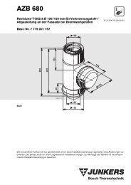
3 Examples of installation of vertical flue duct with roof exit<br />
3.1 Straight flue ducting without<br />
elbows<br />
3.2 Straight flue ducting with two<br />
45°-elbows<br />
L max<br />
L max<br />
ZWB 7-29 CC1<br />
ZB 7-28 CS1<br />
ZSBR 7-28 ICS1<br />
ZWBR 8-30 ICC2<br />
ZBR 8-35 ICS1<br />
ZWBR 11-37 ICC2<br />
ZWB 7-27 HE combi<br />
ZB 7-27 HE system<br />
ZWBR 7-28 HE plus<br />
ZWBR 11-35 HE plus<br />
6.4 m<br />
ZWB 7-29 CC1<br />
ZB 7-28 CS1<br />
ZSBR 7-28 ICS1<br />
ZWBR 8-30 ICC2<br />
ZBR 8-35 ICS1<br />
ZWBR 11-37 ICC2<br />
ZWB 7-27 HE combi<br />
ZB 7-27 HE system<br />
ZWBR 7-28 HE plus<br />
ZWBR 11-35 HE plus<br />
4.4 m<br />
Table 4<br />
Table 5<br />
535<br />
Ø120<br />
535<br />
Ø120<br />
≤ 1310<br />
≤ 1310<br />
B4<br />
B4<br />
Ø98.5<br />
L<br />
Ø98.5<br />
L<br />
≤ 1000<br />
B2<br />
B2<br />
≤ 1000<br />
B2<br />
B4.1<br />
≤ 1000<br />
B6<br />
≤ 1000<br />
71<br />
B2<br />
B6<br />
Fig. 4<br />
6 720 610 703-04.1O<br />
B4.1<br />
Key to Fig. 4 and 5:<br />
B2: <strong>AZB</strong> 804<br />
B4: <strong>AZB</strong> <strong>800</strong><br />
B6: <strong>AZB</strong> 803<br />
Fig. 5<br />
6 720 610 703-05.1O<br />
6 720 610 703 (01.07)<br />
5
Examples of installation of vertical flue duct with roof exit<br />
3.3 Straight flue ducting with two<br />
90°-elbows<br />
ZWB 7-29 CC1<br />
ZB 7-28 CS1<br />
ZSBR 7-28 ICS1<br />
ZWBR 8-30 ICC2<br />
ZBR 8-35 ICS1<br />
ZWBR 11-37 ICC2<br />
ZWB 7-27 HE combi<br />
ZB 7-27 HE system<br />
ZWBR 7-28 HE plus<br />
ZWBR 11-35 HE plus<br />
L max<br />
2.4 m<br />
B3<br />
535<br />
B4<br />
≤ 1000<br />
Ø120<br />
Ø98.5<br />
≤ 1310<br />
L<br />
Table 6<br />
≤ 1000<br />
B2<br />
B2<br />
B3<br />
≤ 1310<br />
535<br />
Ø120<br />
B2<br />
B4.1<br />
≤ 1000<br />
B4<br />
Ø98.5<br />
Fig. 7<br />
6 720 610 703-07.1O<br />
L<br />
B3<br />
B2<br />
≤ 1000<br />
535<br />
Ø120<br />
≤ 1000<br />
140<br />
B4.1<br />
B3<br />
B2<br />
B4<br />
Ø98.5<br />
≤ 1310<br />
6 720 610 703-06.1O<br />
≤ 1000<br />
B2<br />
L<br />
Fig. 6<br />
Key to Fig. 6, 7 and 8:<br />
B2: <strong>AZB</strong> 804<br />
B3: <strong>AZB</strong> 802<br />
B4: <strong>AZB</strong> <strong>800</strong><br />
B3<br />
B2<br />
≤ 1000<br />
≤ 1000<br />
B3<br />
≤ 1000<br />
B2 B2<br />
B4.1<br />
6 720 610 703-08.1O<br />
Fig. 8<br />
6<br />
6 720 610 703 (01.07)
Examples of installation of vertical flue duct with roof exit<br />
3.4 Flue ducting with more than two<br />
elbows<br />
The equivalent pipe length, L e , is calculated from the<br />
sum of the straight lengths of the horizontal and vertical<br />
flue ducting (L horiz , L vert ) and the equivalent lengths of<br />
the elbows. The equivalent length of every elbow fitted<br />
must be included.<br />
The overall equivalent pipe length must be less than the<br />
maximum equivalent pipe length: L e ≤ L e,max .<br />
For vertical flue ducting the following equivalent lengths<br />
apply:<br />
Vertical flue ducting<br />
Boiler<br />
ZWB 7-29 CC1<br />
ZB 7-28 CS1<br />
ZSBR 7-28 ICS1<br />
ZWBR 8-30 ICC2<br />
ZBR 8-35 ICS1<br />
ZWBR 11-37 ICC2<br />
ZWB 7-27 HE combi<br />
ZB 7-27 HE system<br />
ZWBR 7-28 HE plus<br />
ZWBR 11-35 HE plus<br />
Table 7 Pipe lengths<br />
L e,max : maximum equivalent overall pipe length<br />
Equivalent<br />
lengths of<br />
additional<br />
elbows<br />
90° 15-<br />
45°<br />
L e,max<br />
[m] [m] [m]<br />
6.4 2 1<br />
Example:<br />
For a vertical flue system with a vertical length of 4 m<br />
and two 45°-elbows, the equivalent pipe length is calculated<br />
as follows:<br />
Length/<br />
Number<br />
Sectional<br />
equivalent<br />
length<br />
Total<br />
Straight 4 m x 1 = 4 m<br />
length L vert<br />
Straight 0 m x 1 = 0 m<br />
length L horiz<br />
Elbow 90° 0 x 2 m = 0 m<br />
Elbow 45° 2 x 1 m = 2 m<br />
Equivalent pipe length L e<br />
Maximum equivalent<br />
overall pipe length L e,max<br />
L e ≤ L e,max<br />
6 m<br />
6.4 m<br />
Table 8<br />
At 6 m, the equivalent pipe length is shorter than the<br />
maximum equivalent overall length of 6.4 m. This flue<br />
system is therefore acceptable.<br />
Example:<br />
For a vertical flue system with a vertical length of 2 m, a<br />
horizontal length of 0.4 m and two 90°-elbow, the equivalent<br />
pipe length is calculated as follows:<br />
Length/<br />
Number<br />
Sectional<br />
equivalent<br />
length<br />
Total<br />
o.k.<br />
Straight 2 m x 1 = 2 m<br />
length L vert<br />
Straight 0.4 m x 1 = 0.4 m<br />
length L horiz<br />
Elbow 90° 2 x 2 m = 4 m<br />
Elbow 45° 0 x 1 m = 0 m<br />
Equivalent pipe<br />
length L e<br />
Maximum equivalent<br />
overall pipe length L e,max<br />
L e ≤ L e,max<br />
6.4 m<br />
6.4 m<br />
o.k.<br />
Table 9<br />
At 6.4 m, the equivalent pipe length is equal the maximum<br />
equivalent overall length of 6.4 m. This flue system<br />
is therefore acceptable (borderline case).<br />
6 720 610 703 (01.07)<br />
7
Mounting<br />
4 Mounting<br />
4.1 Notes on fitting<br />
• The vertical flue duct <strong>AZB</strong> <strong>800</strong> can be extended at<br />
any point between the heat exchanger and the flue<br />
terminal assembly using the flue duct kits <strong>AZB</strong> 802,<br />
803 or 804.<br />
• For details of the maximum permissible flue pipe<br />
length, refer to the installation examples starting on<br />
page 5.<br />
• The horizontal section of the vertical flue section<br />
should be fitted should be fitted with an upward<br />
incline of 3% (3 cm per metre) in the direction of flow<br />
of the flue gases.<br />
• In damp rooms, the air pipe should be insulated.<br />
4.2.2 Inclined roof<br />
A<br />
α<br />
Table 11<br />
≥ 400 mm, in areas with frequent heavy<br />
snow falls ≥ 500 mm<br />
≤ 60°, in areas with frequent heavy snow<br />
falls ≤ 50°<br />
A<br />
4.2 Roof-exit clearances<br />
4.2.1 Flat roof<br />
Combustible<br />
building material<br />
Non-combustible<br />
building material<br />
X ≥ 1500 mm ≥ 500 mm<br />
Table 10<br />
α<br />
X<br />
Fig. 10<br />
6 720 610 489-13.1O<br />
535<br />
120<br />
6 720 610 703-09.1O<br />
Fig. 9<br />
8<br />
6 720 610 703 (01.07)
Mounting<br />
4.3 Fitting the flue ducting<br />
B Determine the length L V of the air pipe<br />
(refer to fig 4 - fig. 8).<br />
B Slide the flue gas accessories, lightly twisting, into<br />
each other to the stop in the sleeve.<br />
L V<br />
B4<br />
B4<br />
6 720 610 489-014.1O<br />
Fig. 11<br />
B4: <strong>AZB</strong> <strong>800</strong><br />
B Cut off the air pipe at a right angle, deburr the cut<br />
edges and clean.<br />
B Determine the length L A = L V +20 mm of the flue<br />
pipe.<br />
B2<br />
L A<br />
L V<br />
B4<br />
B4.1<br />
Fig. 12<br />
B4: <strong>AZB</strong> <strong>800</strong><br />
20<br />
6 720 610 703-10.1O<br />
B Cut off the flue pipe at a right angle, deburr the cut<br />
edges and clean.<br />
B Lightly grease the seals on the sleeves with a solventfree<br />
grease (e. g. Vaseline).<br />
Fig. 13<br />
B2: <strong>AZB</strong> 804<br />
B4: <strong>AZB</strong> <strong>800</strong><br />
6 720 610 703-11.1O<br />
6 720 610 703 (01.07)<br />
9
Mounting<br />
10<br />
6 720 610 703 (01.07)
Mounting<br />
6 720 610 703 (01.07)<br />
11