Modbus in MAC400_800
Modbus in MAC400_800
Modbus in MAC400_800

You also want an ePaper? Increase the reach of your titles
YUMPU automatically turns print PDFs into web optimized ePapers that Google loves.
<strong>Modbus</strong> <strong>in</strong> <strong>MAC400</strong>/<strong>800</strong><br />
The modbus implementation <strong>in</strong> <strong>MAC400</strong>/<strong>800</strong> is a subset of the <strong>Modbus</strong> Specification V1.1b. This<br />
standard can be downloaded free of charge from the website www.modbus.org.<br />
The serial communications l<strong>in</strong>es normally used for communications between the basic motor and<br />
one of the <strong>in</strong>telligent MAC00-XX modules, can be configured to use the <strong>Modbus</strong> protocol <strong>in</strong>stead<br />
of the standard FastMac protocol.<br />
The <strong>MAC400</strong>/<strong>800</strong> firmware supports the two command types Read Hold<strong>in</strong>g Registers (3) and Write<br />
Multiple Register (0x10). All other commands will result <strong>in</strong> Exception replies (exception type 1,<br />
Illegal Function).<br />
All registers can be read as well as written over <strong>Modbus</strong>, but the number of registers per transfer is<br />
limited to 16 16-bit registers or 8 32-bit registers. Contact JVL if more registers are needed <strong>in</strong> a<br />
s<strong>in</strong>gle transfer.<br />
All registers <strong>in</strong> the <strong>MAC400</strong>/<strong>800</strong> motors are 32-bits. To comply with the clean 16-bit <strong>Modbus</strong><br />
standard, a 32-bit register must be read or written as two consecutive 16-bit registers.<br />
The register address mapp<strong>in</strong>g follows the normal documented register numbers but the address<br />
field, but must be multiplied by two, so to read or write register 3, P_SOLL, use the address 6.<br />
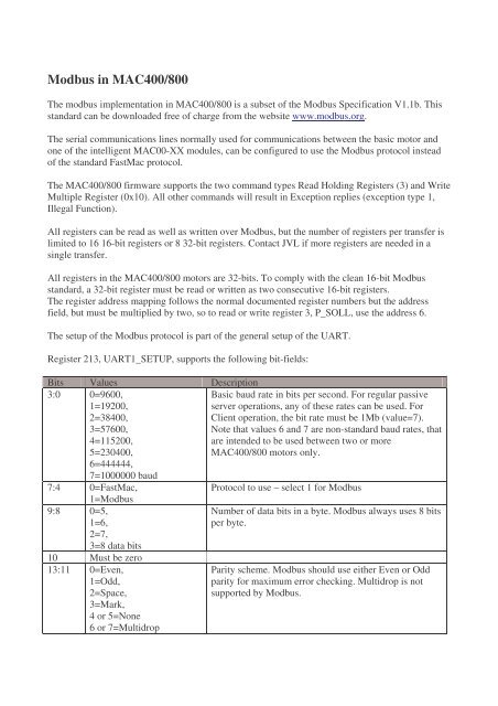
The setup of the <strong>Modbus</strong> protocol is part of the general setup of the UART.<br />
Register 213, UART1_SETUP, supports the follow<strong>in</strong>g bit-fields:<br />
Bits Values Description<br />
3:0 0=9600,<br />
1=19200,<br />
2=38400,<br />
3=57600,<br />
4=115200,<br />
5=230400,<br />
Basic baud rate <strong>in</strong> bits per second. For regular passive<br />
server operations, any of these rates can be used. For<br />
Client operation, the bit rate must be 1Mb (value=7).<br />
Note that values 6 and 7 are non-standard baud rates, that<br />
are <strong>in</strong>tended to be used between two or more<br />
<strong>MAC400</strong>/<strong>800</strong> motors only.<br />
6=444444,<br />
7=1000000 baud<br />
7:4 0=FastMac,<br />
Protocol to use – select 1 for <strong>Modbus</strong><br />
1=<strong>Modbus</strong><br />
9:8 0=5,<br />
1=6,<br />
2=7,<br />
3=8 data bits<br />
10 Must be zero<br />
13:11 0=Even,<br />
1=Odd,<br />
2=Space,<br />
3=Mark,<br />
4 or 5=None<br />
6 or 7=Multidrop<br />
Number of data bits <strong>in</strong> a byte. <strong>Modbus</strong> always uses 8 bits<br />
per byte.<br />
Parity scheme. <strong>Modbus</strong> should use either Even or Odd<br />
parity for maximum error check<strong>in</strong>g. Multidrop is not<br />
supported by <strong>Modbus</strong>.
15:14 0=1,<br />
Number of stop bits to use.<br />
1=1.5,<br />
2=2 stop bits<br />
23:16 0..255 Guard-time. Number of idle bit times between bytes<br />
dur<strong>in</strong>g transmission. These can be seen as additional stop<br />
bits. Normally this value is set to zero, but with some<br />
UARTs that have trouble synchroniz<strong>in</strong>g on long<br />
telegrams, this value can be set to non-zero. Sett<strong>in</strong>g this<br />
value non-zero may help with visually separat<strong>in</strong>g bytes<br />
on an oscilloscope.<br />
25:24 0=Passive server,<br />
1=Active server with<br />
timeout monitor<strong>in</strong>g.<br />
2=Client (bus master)<br />
operation to transfer<br />
requested position and<br />
monitor errors.<br />
27:26 Reserved<br />
31:28 Timeout <strong>in</strong> milliseconds.<br />
For normal operation where a PC or PLC talks to one or<br />
more motors, set this to zero.<br />
If set to One, the motor will set a Communications Error<br />
and stop if it has not received a valid write request to<br />
P_SOLL with<strong>in</strong> the timeout selected <strong>in</strong> bits 31:28.<br />
If set to two, the motor will write a position and read the<br />
error/status register of the client at address 254 once per<br />
sample period. If not both write acknowledge and<br />
error/status data is received with<strong>in</strong> the timeout specified<br />
<strong>in</strong> bits 31:28, the motor will set a Communications error<br />
and stop.<br />
The firmware will use only the power-up value of register 213, so for any changes to take effect, do<br />
a Save <strong>in</strong> Flash operation.<br />
Read Hold<strong>in</strong>g operation:<br />
Request: , 0x03, RegHi, RegLo, CountHi, CountLo, CRC1, CRC2<br />
Offset: [0] [1] [2] [3] [4] [5] [6] [7]<br />
Reply: , 0x03, #Bytes, Reg0Hi, Reg0Lo, Reg1Hi, Reg1Lo, ..... CRC1, CRC2<br />
Example to read P_IST from motor with address 1, values <strong>in</strong> decimal:<br />
1, 3, 0, 20, 0, 2, NN, MM (NN and MM are the CRC-16 bytes)<br />
Write Multiple Register operation:<br />
Request: , 0x10, RegHi, RegLo, CountHi, CountLo, NBytes, Val0Hi, Val0Lo, ..., CRC1, CRC2<br />
Offset: [0] [1] [2] [3] [4] [5] [6] [7] [8]<br />
Reply: , 0x10, RegHi, RegLo, CountHi, CountLo, CRC1, CRC2<br />
Example to write P_SOLL to motor with address 1, values <strong>in</strong> decimal:<br />
1, 16, 0, 6, 0, 2, 4, bb, aa, dd, cc, NN, MM (NN and MM are the CRC-16 bytes)<br />
This would write a 32-bit hexadecimal value of ddccbbaa – note the byte-pack<strong>in</strong>g.