Installation Instructions - KACO new energy, Inc.
Installation Instructions - KACO new energy, Inc.
Installation Instructions - KACO new energy, Inc.

You also want an ePaper? Increase the reach of your titles
YUMPU automatically turns print PDFs into web optimized ePapers that Google loves.
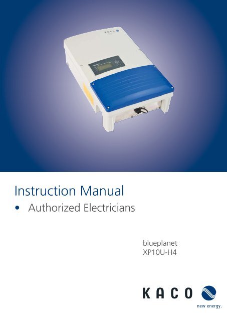
Instruction Manual<br />
• Authorized Electricians<br />
blueplanet<br />
XP10U-H4
<strong>Installation</strong> <strong>Instructions</strong><br />
for authorized electricans<br />
blueplanet<br />
XP10U-H4<br />
Contents<br />
1 General Notes ............................................ 4<br />
1.1 About this documentation .................................4<br />
1.2 Design features .......................................................4<br />
2 Safety ......................................................... 6<br />
2.1 Intended use ............................................................6<br />
2.2 Protection features ................................................ 7<br />
2.3 Standards and regulations .................................. 7<br />
3 Description ................................................ 8<br />
3.1 How it works ............................................................8<br />
3.2 Unit description ......................................................8<br />
4 Technical Data .......................................... 11<br />
4.1 Electrical Data ......................................................... 11<br />
4.2 Mechanical Data ....................................................12<br />
5 Transportation and Delivery ...................13<br />
5.1 Delivery .....................................................................13<br />
5.2 Transportation ........................................................13<br />
6 Mounting the Inverter .............................14<br />
7 Installing the Inverter ..............................16<br />
7.1 Opening the connection area ......................... 16<br />
7.2 Drilling holes for electrical and interface<br />
connection .............................................................. 16<br />
7.3 Carrying out the electrical connection .........17<br />
7.4 Connecting the interfaces ................................22<br />
7.5 Sealing the connection area ............................25<br />
7.6 Starting up the inverter ......................................25<br />
8 Configuration and Operation ................ 26<br />
8.1 Controls ....................................................................26<br />
8.2 Initial start-up ........................................................29<br />
8.3 Menu structure......................................................29<br />
8.4 Monitoring the inverter .....................................33<br />
8.5 Performing a software update ........................35<br />
9 Maintenance/Troubleshooting.............. 36<br />
9.1 Visual inspection ..................................................36<br />
9.2 Cleaning the inverter externally .....................36<br />
9.3 Shutting down for maintenance and<br />
troubleshooting ....................................................36<br />
9.4 Faults ......................................................................... 37<br />
9.5 Messages on the display and the<br />
“Fault” LED ............................................................. 40<br />
9.6 Replacing or cleaning the fan ......................... 44<br />
10 Service ...................................................... 45<br />
11 Shutdown/Disassembly .........................46<br />
11.1 Shutting down the inverter ............................. 46<br />
11.2 Deinstalling the inverter ................................... 46<br />
11.3 Dismantling the inverter ................................... 46<br />
12 Recycling and disposal ........................... 47<br />
13 Appendix .................................................48<br />
<strong>Installation</strong> <strong>Instructions</strong> blueplanet XP10U-H4 Page 3
General Notes<br />
1 General Notes<br />
1.1 About this documentation<br />
WARNING<br />
Improper handling of the inverter can be hazardous<br />
› IMPORTANT SAFETY INSTRUCTIONS.<br />
› You must read and understand the operating instructions before you can install and use the<br />
inverter safely.<br />
This manual is intended for inverter model blueplanet XP10U-H4 and shall be followed during installation and maintenance<br />
of this inverter model.<br />
1.1.1 Other Applicable Documents<br />
During installation, observe all assembly and installation instructions for components and other parts of the system.<br />
These instructions are delivered together with the respective components and other parts of the system.<br />
Some of the documents which are required for registering and approving your photovoltaic (PV) system are<br />
included with the operating instructions.<br />
1.1.2 Retention of documents<br />
SAVE THESE INSTRUCTIONS. These instructions and other documents must be stored near the system and be<br />
available whenever they are needed.<br />
1.2 Design features<br />
1.2.1 Symbols used in this document<br />
General hazard symbol<br />
Risk of fire or explosion<br />
High voltage<br />
Risk of burns<br />
Authorised electrician<br />
The tasks indicated with this symbol may only be carried out by an authorised<br />
electrician.<br />
1.2.2 Description of safety instructions<br />
DANGER<br />
Imminent danger<br />
Failure to observe this warning will lead directly to serious bodily injury or death.<br />
WARNING<br />
Potential danger<br />
Failure to observe this warning may lead to serious bodily injury or death.<br />
CAUTION<br />
Low-risk hazard<br />
Failure to observe this warning will lead to minor or moderate bodily injury.<br />
Page 4<br />
blueplanet <strong>Installation</strong> <strong>Instructions</strong> Powador 10.0 TL3, 12.0 TL3, 14.0 TL3_EN
General Notes<br />
CAUTION<br />
Hazard with risk of property damage<br />
Failure to observe this warning will lead to property damage.<br />
1.2.3 Description of additional information<br />
NOTICE<br />
Useful information and notes<br />
1.2.4 Description of action instructions<br />
a) One-step actions or actions that can be carried out in any sequence:<br />
Action instructions<br />
↻ Prerequisite(s) for your action(s) (optional)<br />
Carry out action.<br />
(Additional actions, if applicable)<br />
» Result of your action(s) (optional)<br />
b) Multi-step action instructions that must be carried out in a fixed sequence:<br />
Action instructions<br />
↻ Prerequisite(s) for your actions (optional)<br />
1. Carry out action.<br />
2. Carry out action.<br />
3. (Additional actions, if applicable)<br />
» Result of your actions (optional)<br />
blueplanet <strong>Installation</strong> <strong>Instructions</strong> Powador 10.0 TL3, 12.0 TL3, 14.0 TL3_EN Page 5
Safety<br />
2 Safety<br />
DANGER<br />
Lethal voltages are still present in the terminals and leads of the inverter even after the<br />
inverter has been switched off and disconnected.<br />
Severe injuries or death if the leads and/or terminals in the inverter are touched.<br />
Only authorised electricians who are approved by the supply grid operator may open, install and<br />
maintain the inverter.<br />
› Keep the inverter closed when the unit is in operation.<br />
› Do not touch the leads and/or terminals when switching the unit on and off.<br />
› Do not make any modifications to the inverter.<br />
The electrician is responsible for observing all existing standards and regulations.<br />
• Keep unauthorized persons away from the inverter and PV system.<br />
• Be sure to observe IEC 60364-7-712:2002 (“Requirements for special installations or locations – solar photovoltaic<br />
(PV) power supply systems”) in particular.<br />
• Ensure operational safety by providing proper grounding, conductor dimensioning and appropriate protection<br />
against short circuiting.<br />
• Observe the safety instructions on the inverter and in these operating instructions.<br />
• Switch off all voltage sources and secure them against being inadvertently switched back on before performing<br />
visual inspections and maintenance.<br />
• When taking measurements while the inverter is live:<br />
– Do not touch the electrical connections.<br />
– Remove all jewellery from your wrists and fingers.<br />
– Ensure that the testing equipment is in safe operating condition.<br />
• Stand on an insulated surface when working on the inverter while it is switched on.<br />
• Modifications to the surroundings of the inverter must comply with the applicable national and local standards.<br />
• When working on the PV generator, it is also necessary to switch off the DC voltage with the DC disconnector in<br />
addition to disconnecting the PV generator from the grid.<br />
2.1 Intended use<br />
The inverter converts the DC voltage generated by the PV modules into AC voltage and leads this into the grid<br />
feed-in. The inverter is built according to the state of the art and recognised safety regulations. Nevertheless,<br />
improper use may cause lethal hazards for the operator or third parties, or may result in damage to the unit and<br />
other property.<br />
Operate the inverter only with a permanent connection to the public power grid.<br />
Any other or additional use is not considered the intended use. This includes:<br />
• Mobile use<br />
• Use in rooms where there is a risk of explosion<br />
• Use in rooms where the humidity is higher than 95%<br />
• Operation outside of the specification intended by the manufacturer<br />
• Standalone operation.<br />
Page 6 <strong>Installation</strong> <strong>Instructions</strong> blueplanet XP10U-H4
Safety<br />
2.2 Protection features<br />
For your safety, the following monitoring and protective functions are integrated into Powador inverters:<br />
• Overvoltage conductors/varistors to protect the power semiconductors from high-<strong>energy</strong> transients on the<br />
grid and generator side<br />
• Temperature monitoring of the heat sink<br />
• EMC filters to protect the inverter from high-frequency grid interference<br />
• Grid-side grounded varistors to protect the inverter against burst and surge pulses<br />
• Islanding detection according to VDE 0126-1-1<br />
2.3 Standards and regulations<br />
Electrical conformity according to U.S., Canadian and international safety operating standards and code<br />
requirements:<br />
• UL 1741-1:1999 Rev. May 2007<br />
• CSA 22.2 No. 107-1:2001 Rev 2006<br />
• IEEE Std. 1547-2003<br />
• IEEE Std. 1547.1-2005<br />
• FCC Part 15 Class B<br />
• NEC Sections 690 (ANSI/NFPA 70)<br />
• Directive concerning Electromagnetic Compatibility with Class B (Council Directive 2004/108/EC)<br />
• Low Voltage Directive (Council Directive 2006/95/EC)<br />
The blueplanet inverter has complete on-board overcurrent, over-temperature and anti-islanding protection.<br />
<strong>Installation</strong> <strong>Instructions</strong> blueplanet XP10U-H4 Page 7
Description<br />
3 Description<br />
3.1 How it works<br />
The inverter converts the DC voltage generated by the PV modules into AC voltage and leads this into the grid<br />
feed-in. The feed-in process begins when there is sufficient irradiance and a specific minimum voltage is present<br />
in the inverter. If, as nightfall approaches, the voltage drops below the minimum voltage value, feed-in mode ends<br />
and the inverter switches off.<br />
3.2 Unit description<br />
3.2.1 Inverter as part of a PV system<br />
3.2.1.1 System layout<br />
PV generator<br />
PV generator<br />
v<br />
Inverter<br />
Inverter<br />
Safety<br />
fuse<br />
Safety<br />
fuse<br />
Consumer<br />
Reference<br />
meter<br />
KWh<br />
KWh<br />
Feed-in meter<br />
Main switch<br />
Selective main switch<br />
Grid connection<br />
point<br />
Figure 1:<br />
Overview circuit diagram for a system with two inverters<br />
Page 8 <strong>Installation</strong> <strong>Instructions</strong> blueplanet XP10U-H4
Description<br />
3.2.1.2 A summary of the components<br />
PV generator<br />
The PV generator, i.e. the PV modules, converts the radiant <strong>energy</strong> of sunlight into electrical <strong>energy</strong>.<br />
DC terminal point<br />
Variants of parallel connection of several generator strings:<br />
• To a DC terminal point between the DC generator and inverter<br />
• Directly to the inverter (plug connectors for 4 (2x2) strings are provided on the inverter)<br />
• Directly to the PV generator with a positive and negative lead to the inverter<br />
Line fuses<br />
Safety fuses are suitable.<br />
Feed-in meter<br />
The feed-in meter is specified and installed by the power supply company. Some power supply companies also<br />
allow the installation of your own calibrated meters.<br />
Selective main switch<br />
If you have questions about the selective main switch, contact your power supply company.<br />
3.2.2 Design of the inverter<br />
1<br />
2<br />
3<br />
4<br />
5<br />
Figure 2: Design of the inverter<br />
Key<br />
1 Operator panel 4 USB interface<br />
2 Cover for the connection area 5 Mounting plate<br />
3 Connection board<br />
<strong>Installation</strong> <strong>Instructions</strong> blueplanet XP10U-H4 Page 9
Description<br />
3.2.3 Electrical functions<br />
3.2.3.1 Fault signal relay<br />
A potential-free relay contact is integrated in the inverter. The contact closes as soon as there is a fault during<br />
operation.<br />
For the connection, see section 7.3 on page 26.<br />
3.2.4 Interfaces<br />
The inverter offers the following interfaces for communication and remote monitoring:<br />
• RS485 interface<br />
• Ethernet interface<br />
• USB interface<br />
• S0 interface<br />
You configure the interfaces and the web server in the configuration menu.<br />
3.2.4.1 RS485 interface<br />
Use this monitoring variant if you cannot check the function of the system on-site on a regular basis, e.g. if your<br />
place of residence is located a great distance from the system. To connect the RS485 interface, contact your<br />
authorised electrician.<br />
For monitoring your PV system using the RS485 interface, <strong>KACO</strong> <strong>new</strong> <strong>energy</strong> GmbH offers the following units:<br />
Powador-proLOG S to XL (optional)<br />
Powador-proLOG allows you to monitor up to 31 inverters simultaneously. Depending on the product version,<br />
Powador-proLOG sends yield and operating data by SMS or e-mail.<br />
Powador-link RS485 (optional)<br />
Use the Powador-link RS485 to bridge long distances between several inverters or between an inverter and the<br />
Powador-proLOG by means of wireless radio transmission.<br />
3.2.4.2 Ethernet interface<br />
The monitoring can occur directly on the unit using the integrated Ethernet interface. A local web server is installed<br />
in the unit for this purpose.<br />
For monitoring a system comprising several inverters, we recommend you use an external data logging and<br />
monitoring system.<br />
3.2.4.3 USB interface<br />
The USB connection of the inverter is a type A socket. It is located on the connection board on the underside of the<br />
inverter under a cover. The USB connection is specified to draw 100 mA of power. Use the USB interface for reading<br />
out stored operating data and loading software updates using a FAT32-formatted USB stick.<br />
3.2.4.4 S0 interface<br />
The S0 interface transmits pulses between a pulsing counter and a tariff metering unit. It is a galvanically isolated<br />
transistor output. It is designed according to DIN EN 62053-31:1999-04 (Pulse output devices for electromechanical<br />
and electronic meters).<br />
The S0 interface pulse rate can be chosen in three unit intervals (500, 1,000 and 2,000 pulses/kWh).<br />
Page 10 <strong>Installation</strong> <strong>Instructions</strong> blueplanet XP10U-H4
Technical Data<br />
Input Levels<br />
Max. PV generator power [W]<br />
DC MPP range from [V] to [V]<br />
Operating range from [V] to [V]<br />
Starting voltage [V]<br />
Open circuit voltage [V]<br />
XP10U-H4<br />
12,000<br />
280 ... 550<br />
200 ... 550*<br />
250<br />
600 (start to 600)<br />
Max.<br />
rated current [A]<br />
2 x18.6<br />
Max. power per tracker [W] 10,200<br />
Number of strings<br />
Number of MPP controls<br />
Polarity safeguard<br />
DC overvoltage category<br />
2 x 2<br />
2<br />
Short-circuit diode<br />
II<br />
18.6<br />
Output Levels<br />
Rated power [VA]<br />
Max. power [VA]<br />
Grid voltage L-N/L-L [V]<br />
Grid voltage operating range L-N [V]<br />
Rated current [A]<br />
Max. current [A]<br />
Rated frequency [Hz]<br />
Power factor at full load (cos phi)<br />
Number of feed-in phases<br />
Distortion factor [%]<br />
AC overvoltage category<br />
General electrical data<br />
ciency [%]<br />
ciency [%]<br />
Internal consumption: night [W]<br />
Feed-in starts at [W]<br />
Circuit design<br />
Transformer unit<br />
CE conformity<br />
Tabelle 1:<br />
Electrical Data<br />
10,000<br />
10,000<br />
277/480 (USA)<br />
234-304<br />
3 x 12.1<br />
3 x 12.1<br />
60 (58.9 ... 61.3)<br />
> .99<br />
3<br />
5.5<br />
III<br />
97.4<br />
97.0<br />
< 1.5<br />
20<br />
Transformerless<br />
No<br />
Yes<br />
c
Technical Data<br />
4.2 Mechanical Data<br />
XP10U-H4<br />
Display<br />
LCD graphical display, 3 LEDs<br />
Controls<br />
4-way key, 2 keys<br />
Interfaces<br />
Ethernet, USB, RS485, S0<br />
Fault signal relay<br />
Potential-free NO contact, 277 V/1 A<br />
Connections for AC PCB terminal<br />
PCB terminals inside the unit (max. cross section: 7 AWG)<br />
DC connections<br />
PCB terminals inside the unit (max. cross section: 11 AWG)<br />
Connection for Ethernet cable connection<br />
RJ45 connector<br />
Optional DC connection -<br />
Ambient temperature range [°F]<br />
-13 ... 140 (-25°C ... 60 °C)<br />
Storage temperature range [°F]<br />
-22 ... 158 (-30°C ... 70°C)<br />
Humidity range (non-condensing) [%] 0 ... 95<br />
Maximum installation elevation [ft above sea level] 6,561<br />
Temperature monitoring<br />
Yes<br />
Cooling<br />
Fan cooling<br />
Protection class NEMA 4<br />
Degree of contamination 2<br />
DC disconnect<br />
Built-in<br />
Housing<br />
Aluminum cast<br />
H x W x D [in]<br />
27.2 x 16.5 x 7.9 (690 x 420 x 200 mm)<br />
Total weight [lbs]<br />
88 (40 kg)<br />
Tabelle 2: Mechanical Data<br />
Page 12 <strong>Installation</strong> <strong>Instructions</strong> blueplanet XP10U-H4
Transportation and Delivery<br />
5 Transportation and Delivery<br />
5.1 Delivery<br />
Every inverter leaves our factory in proper electrical and mechanical condition. Special packaging ensures that they<br />
are transported safely. The shipping company is responsible for any transport damage that occurs.<br />
Scope of delivery<br />
• 1 inverter<br />
• 1 wall bracket<br />
• 1 connection board<br />
• 1 installation kit<br />
• 1 documentation set<br />
Checking your delivery<br />
1. Thoroughly inspect your inverter.<br />
2. Immediately notify the shipping company in case of the following:<br />
– Damage to the packaging that indicates that the inverter may have been damaged<br />
– Obvious damage to the inverter<br />
3. Immediately send a damage report to the shipping company.<br />
The damage report must be delivered to the shipping company in writing within six days following receipt of the<br />
inverter. We will be glad to help you, if necessary.<br />
5.2 Transportation<br />
WARNING<br />
Impact hazard, risk of breakage to the inverter<br />
› Securely pack the inverter for transport.<br />
› Carefully transport the inverter using the the carrying handles of the pallet.<br />
› Do not subject the inverter to shocks.<br />
For safe transportation of the inverter, use the holding openings in the carton.<br />
<strong>Installation</strong> <strong>Instructions</strong> blueplanet XP10U-H4 Page 13
Mounting the Inverter<br />
Authorised electrician<br />
6 Mounting the Inverter<br />
DANGER<br />
Risk of fatal injury from fire or explosions<br />
Fire caused by flammable or explosive materials in the vicinity of the inverter can lead to serious<br />
injuries.<br />
› Do not mount the inverter in an area at risk of explosion or in the vicinity of highly flammable<br />
materials.<br />
CAUTION<br />
Risk of burns from hot housing components.<br />
Coming into contact with the housing can cause burns.<br />
<strong>Installation</strong> space<br />
› Mount the inverter so that it cannot be touched unintentionally.<br />
• As dry as possible, climate-controlled, with the waste heat dissipated away from the inverter<br />
• Unobstructed air circulation<br />
• When installing the unit in a control cabinet, provide forced ventilation so that the heat is sufficiently dissipated<br />
• Easily accessible from the front and sides<br />
• Protected from direct sunshine outdoors<br />
• For easy operation, ensure during installation that the display is slightly below eye level.<br />
Wall<br />
• With sufficient load-bearing capacity<br />
• Accessible for installation and maintenance<br />
• Made from heat-resistant material (up to 194°F/90°C)<br />
• Flame resistant<br />
• Minimum clearance during installation: see Fig. 6 on page 15 and Fig. 7 on page 15.<br />
CAUTION<br />
Use suitable mounting fixtures.<br />
› Only use the supplied mounting fixtures.<br />
› Mount the inverter upright on a vertical wall only.<br />
NOTICE<br />
Power reduction due to heat accumulation.<br />
If the recommended minimum clearances are not observed, the inverter can have power regulation<br />
and a protective shutdown due to insufficient ventilation and the associated heat<br />
› Maintain minimum clearances.<br />
› Provide for sufficient heat dissipation.<br />
Page 14 <strong>Installation</strong> <strong>Instructions</strong> blueplanet XP10U-H4
Mounting the Inverter<br />
Authorised electrician<br />
54 3/5<br />
16<br />
10 59/260<br />
22 1/4<br />
13<br />
44 1/10<br />
Figure 3: <strong>Instructions</strong> for wall mounting<br />
Figure 4: Drill stencil for wall mounting with<br />
minimum clearances (inches)<br />
Clearance from ceiling 20 in<br />
Clearance from another inverter 27 3/5 in<br />
1<br />
2<br />
10 in<br />
3<br />
10 in<br />
10 in<br />
4<br />
5<br />
Clearance from the floor 20 in<br />
Clearance from another inverter 27 3/5 in<br />
Figure 5: Minimum clearances/mounting plate<br />
Key<br />
1 Fixings for mounting 4 Detachment protector<br />
2 Mounting plate 5 Suspension brackets (back of housing)<br />
3 Screws for mounting<br />
Mounting the inverter<br />
1. Mark the positions of the drill holes using the cut-outs in the mounting plate.<br />
NOTICE: The minimum clearances between two inverters, or the inverter and the ceiling/floor have already<br />
been taken into account in the drawing.<br />
2. Fix mounting plate to the wall with the supplied mounting fixtures.<br />
Make sure that the mounting plate is oriented correctly.<br />
3. Hang the inverter on the mounting plate using the suspension brackets on the back of the housing.<br />
4. Fix the inverter with the enclosed screws to the detachment protector at the connection area.<br />
» The mounting of the inverter is complete. Continue with the installation.<br />
<strong>Installation</strong> <strong>Instructions</strong> blueplanet XP10U-H4 Page 15
Installing the Inverter<br />
Authorised electrician<br />
7 Installing the Inverter<br />
DANGER<br />
Lethal voltages are still present in the terminals and leads of the inverter even after the<br />
inverter has been switched off and disconnected.<br />
Severe injuries or death if the leads and terminals in the inverter are touched.<br />
Only authorised electricians who are approved by the supply grid operator may open and install the<br />
inverter.<br />
The inverter must be mounted in a fixed position before being connected electrically.<br />
› Observe all safety regulations and the currently applicable technical connection specifications of<br />
the responsible power supply company.<br />
› Disconnect the AC and DC sides.<br />
› Secure them against being inadvertently switched back on.<br />
› Assure that the AC and DC sides are completely voltage-free.<br />
› Connect the inverter only after the aforementioned steps have been taken.<br />
NOTICE<br />
Install the inverter in accordance with NEC, ANSI/NFPA 70.<br />
7.1 Opening the connection area<br />
Opening the connection area<br />
↻ You have mounted the inverter on the wall.<br />
1. Unscrew the four Torx screws from the front side of the connection cover.<br />
2. Pull down the connection cover.<br />
» Carry out the electrical connection.<br />
7.2 Drilling holes for electrical and interface connection<br />
The inverter is shipped with a connection board. You are required to drill holes into the board to accomodate the<br />
AC, DC and interface connection leads.<br />
In order to avoid interference between current-carrying leads and interface cables, adher to the following drawing:<br />
4<br />
3<br />
2<br />
Figure 6: Connection board<br />
1<br />
Page 16 <strong>Installation</strong> <strong>Instructions</strong> blueplanet XP10U-H4
Installing the Inverter<br />
Authorised electrician<br />
Key<br />
1 Connection area for DC leads 3 Connection area for AC leads<br />
2 Connection area for interface and<br />
grounding leads<br />
4 USB port<br />
7.3 Carrying out the electrical connection<br />
Make the connection to the PV generator and the grid connection via the PCB terminals in the connection area of<br />
the inverter. Maintain the following conductor cross-sections:<br />
AC connection<br />
Max. conductor cross-section without wire sleeves 6 AWG 8 AWG<br />
Max. conductor cross-section with wire sleeves 7 AWG 11 AWG<br />
Length of insulation to be stripped off 2/5 in 3/5 in<br />
DC connection<br />
7.3.1 Connecting the inverter to the power grid<br />
The grid connection leads are connected on the right side of the connection area (see figure 7).<br />
DANGER<br />
Risk of fatal injury due to electric shock<br />
Severe injuries or death will result if the live connections are touched.<br />
› Disconnect the inverter from all power sources before you insert the grid power lead into the unit.<br />
CAUTION<br />
Risk of fire<br />
Insufficient over current protection can increase the risk of fire.<br />
› Connect only to a circuit provided with a 64A branch circuit over current protection in accordance<br />
with the national electrical code ANSI/NFPA 70.<br />
Recommended conductor cross-sections and fuse protection of NYM leads for fixed wiring according to<br />
VDE 0100 part 430<br />
We recommend the following conductor cross-sections for cable lengths up to 60 ft:<br />
AWG 4 up to AWG 10, 75° Copper Wire. Larger cross-sections schould be used for longer leads. 25A breaker.<br />
This unit is provided with fixed trip limits and shall not be aggregated above 30kw on a single point of common<br />
connection.<br />
NOTICE<br />
The installation shall indicate that wiring methods in accordance with the NEC, ANSI/NFPA 70 are to<br />
be used.<br />
NOTICE<br />
Use copper conductors only.<br />
<strong>Installation</strong> <strong>Instructions</strong> blueplanet XP10U-H4 Page 17
Installing the Inverter<br />
Authorised electrician<br />
NOTICE<br />
When the lead impedance is high (i.e. long grid-side leads), the voltage at the grid terminals of the<br />
inverter will increase during feed-in to the grid. The inverter monitors this voltage. If it exceeds the<br />
country-specific line overvoltage limit value, the inverter switches off.<br />
› Ensure that the lead cross-sections are sufficiently large or that the lead lengths are sufficiently<br />
short.<br />
Making the grid connection<br />
↻ Drill a hole for the AC leads into the connection board.<br />
1. Remove the outer cladding of the AC leads.<br />
2. Insert the AC leads through the hole into the connection area through the conduit pipe.<br />
3. Strip the insulation from the AC leads.<br />
4. Open the locks of the PCB terminals.<br />
5. Connect the leads in accordance with the labelling of the PCB terminals.<br />
6. Close the locks of the PCB terminals.<br />
7. Check that all connected leads are tightly seated.<br />
» The inverter is now connected to the power grid.<br />
NOTICE<br />
An AC-side disconnection unit must be provided in the final installation. This disconnection unit<br />
must installed in such a manner that access to it is possible at any time without hindrance.<br />
If a residual current circuit breaker is necessary due to the installation specification, then a type A AFI<br />
(AC/DC-sensitive residual current circuit breaker) must be used.<br />
7.3.2 Connecting the PV generator<br />
Connect the PV generator to the 4 DC positive and the 4 DC negative connection terminals in the connection area<br />
of the inverter.<br />
DANGER<br />
Risk of fatal injury due to contact voltages.<br />
› During installation: Electrically disconnect the DC positive and DC negative from the protective<br />
earth (PE).<br />
Removing the connection without previously disconnecting the inverter from the DC generator can<br />
result in a hazard to health and damage to the inverter.<br />
WARNING<br />
No internal GFDI.<br />
This unit is not provided with a GFDI (ground-fault detector-interrupter). The inverter must be used<br />
with an external GFDI device as required by the article 690 of the national electrical code for the<br />
installation location.<br />
Page 18 <strong>Installation</strong> <strong>Instructions</strong> blueplanet XP10U-H4
Installing the Inverter<br />
Authorised electrician<br />
MPP<br />
tracker A<br />
MPP<br />
tracker B<br />
Figure 7: Connection terminals for DC positive and DC negative leads<br />
7.3.2.1 Before the connection<br />
Ensure that there is no ground fault<br />
1. Determine the DC voltage between the<br />
– Protective earth (PE) and the positive lead of the PV generator<br />
– Protective earth (PE) and the negative lead of the<br />
PV generator<br />
If stable voltages can be measured, there is a ground fault in the DC generator or its wiring. The ratio between the<br />
measured voltages gives an indication as to the location of this fault.<br />
2. Rectify any faults before taking further measurements.<br />
3. Determine the electrical resistance between the<br />
– Protective earth (PE) and the positive lead of the PV generator<br />
– Protective earth (PE) and the negative lead of the PV generator<br />
Low resistance (< 2 MΩ) indicates a high-ohm ground fault of the DC generator.<br />
4. Rectify any faults before connecting the DC generator.<br />
7.3.2.2 Maximum input power<br />
The input power of the inverter is limited only by the maximum input current of 18.6 A per input. This causes the<br />
maximum input power per path to increase with the input voltage.<br />
A detailed table with power values as a function of the DC voltage can be found in the appendix.<br />
NOTICE<br />
The overall power of the unit continues to be limited. If one input is connected to more than<br />
P(DCmax)/2, the maximum input power of the second input decreases accordingly. Take care that<br />
the maximum input power is not exceeded.<br />
<strong>Installation</strong> <strong>Instructions</strong> blueplanet XP10U-H4 Page 19
Installing the Inverter<br />
Authorised electrician<br />
7.3.2.3 Recommended standard connection<br />
Equal MPP voltages must be applied to input 1 and 2, as well as inputs 3 and 4. The MPP voltages of the two DC<br />
paths can be different. They are tracked by separate, independently operating MPP trackers (MPP trackers A and B).<br />
(n 1<br />
=n 2<br />
, n 3<br />
=n 4<br />
).<br />
Electrical data for standard connection<br />
Connection of the DC inputs Number of modules per string n 1<br />
=n 2<br />
, n 3<br />
=n 4<br />
P max<br />
I max<br />
per string < 6 kW<br />
MPP trackers A+B together < 12 kW<br />
< 18.6 A per tracker<br />
MPP tracker A<br />
MPP tracker B<br />
U MPP<br />
= 350 - 800 V<br />
U MPP<br />
= 350 - 800 V<br />
n 1<br />
= n 2<br />
n 3<br />
= n 4<br />
Figure 8: Recommended standard connection<br />
7.3.2.4 Parallel input connection<br />
The DC inputs can also be connected in parallel. Only strings with identical MPP voltage can be connected in<br />
parallel (n 1<br />
=n 2<br />
=n m<br />
).<br />
The maximum input current rises to 37.2 A for parallel connection.<br />
In case of a parallel input connection, MPP trackers A and B must be bridged. If input 1 is connected to input 2 and<br />
input 3 is connected to input 4, then there is no parallel operation and the maximum input current continues to be<br />
18.6 A. Parallel operation is automatically recognized by the inverter.<br />
Page 20 <strong>Installation</strong> <strong>Instructions</strong> blueplanet XP10U-H4
Installing the Inverter<br />
Authorised electrician<br />
Electrical data for parallel connection<br />
Connection of the DC inputs<br />
P max<br />
I max<br />
Number of modules per string n 1<br />
=n=n m<br />
< 12 kW<br />
< 37.2 A<br />
MPP tracker A<br />
MPP tracker B<br />
MPP tracker A<br />
MPP tracker B<br />
U MPP<br />
= 350 - 800 V<br />
...<br />
U MPP<br />
= 350 - 800 V<br />
...<br />
n 1<br />
= n 2<br />
= n m<br />
n 1<br />
= n 2<br />
= n m<br />
Figure 9: Parallel input connection in the<br />
generator junction box<br />
Figure 10: Parallel input connection with Y adapter,<br />
short circuit of MPP tracker B<br />
7.3.2.5 Unconnected inputs<br />
NOTICE<br />
If one of the MPP trackers (A or B) is not used it must be short-circuited. Otherwise, faults can occur<br />
in the self-test of the unit and the feed-in operation is not guaranteed. This does not lead to damage<br />
to the unit.<br />
The recommended standard connection or the parallel input connection should be selected as<br />
a matter of course before an MPP tracker is short-circuited and therefore remains unused.<br />
<strong>Installation</strong> <strong>Instructions</strong> blueplanet XP10U-H4 Page 21
Installing the Inverter<br />
Authorised electrician<br />
7.3.2.6 Connecting the PV generator<br />
DANGER<br />
Risk of fatal injury due to electric shock<br />
Severe injuries or death will result if the live connections are touched. When there is irradiance, DC<br />
voltage is present on the open ends of the DC leads.<br />
› Do not touch the open ends of the leads.<br />
› Avoid short circuits.<br />
Connecting the PV generator<br />
↻ Drill one hole for each DC negative and DC positive lead into the connection board.<br />
1. Remove the outer cladding of the DC leads.<br />
2. Insert the DC leads into the connection area through the conduit pipes.<br />
3. Strip the insulation from the DC leads.<br />
4. Connect the leads to the PCB terminals in accordance with the labelling.<br />
» The inverter is connected to the PV generator.<br />
7.3.3 Grounding the housing<br />
An optional grounding of the housing is possible at the grounding point provided for that purpose in the connection<br />
area of the inverter. Please observe any national installation regulations in this regard.<br />
Ground the housing of the inverter, if necessary, at the grounding point provided for that purpose in the connection<br />
area of the inverter. It is marked with the symbol.<br />
Figure 11: Grounding point in the connection area<br />
Grounding the housing<br />
↻ Drill a hole for the grounding lead into the connection board.<br />
1. Remove the outer cladding from the grounding lead.<br />
2. Insert the grounding lead into the connection area through the conduit pipe.<br />
3. Remove the insulation from the grounding lead.<br />
4. Furnish the stripped lead with an M6 ring cable lug.<br />
5. Screw the ring cable lug to the grounding point with an M6 screw.<br />
6. Check for firm seating of the lead.<br />
7.4 Connecting the interfaces<br />
All interface connectors are located on the connection board. Drill holes for the conduits into the connection<br />
board.<br />
Page 22 <strong>Installation</strong> <strong>Instructions</strong> blueplanet XP10U-H4
Installing the Inverter<br />
Authorised electrician<br />
DANGER<br />
Risk of fatal injury due to electric shock<br />
Severe injury or death from improper use of the interface connections and non-observance of<br />
protection class III.<br />
› The SELV circuits (SELV: safety extra low voltage) can only be connected to other SELV circuits with<br />
protection class III.<br />
NOTICE<br />
When laying the interface connection cables, note that too little clearance to the DC or AC leads can<br />
cause interference during data transfer.<br />
Ethernet<br />
RS485 RCL S0 ERR<br />
B A B A + - + -<br />
Figure 12: Connection area: Connection and pinout of the interfaces<br />
7.4.1 Connecting the RS485 bus<br />
blueplanet<br />
Inverters<br />
Terminal unit<br />
blueplanet<br />
Inverters<br />
blueplanet<br />
Inverters<br />
Kaco<br />
proLOG<br />
Communication<br />
230 VAC<br />
Figure 13: RS485 interface wiring diagram<br />
<strong>Installation</strong> <strong>Instructions</strong> blueplanet XP10U-H4 Page 23
Installing the Inverter<br />
Authorised electrician<br />
NOTICE<br />
Different manufacturers interpret the standard on which the RS485 protocol is based in different<br />
ways. Note that the wire designations (- and +) for wires A and B can be different depending on the<br />
manufacturer.<br />
NOTICE<br />
Calculating efficiency by measuring the current and voltage values leads to unusable results due to<br />
the tolerances of the measurement devices. The sole purpose of these measured values is to monitor<br />
the basic operation of the system.<br />
Connecting the RS485 bus<br />
Maximum length of the RS485 wiring: 1,200 m under optimal conditions.<br />
Maximum number of connected bus devices: 31 inverters + 1 data monitoring unit.<br />
<br />
Use twisted, shielded data lines.<br />
Recommendation (using wire sleeves)<br />
– LI2YCYv (TP) black for laying cable outside and in the ground 2 x 2 x 0.5<br />
– LI2YCY (TP) grey for dry and moist spaces 2 x 2 x 0.5<br />
↻ Drill a hole for the RS485 connection cable into the connection board.<br />
1. Thread the connection cable through the hole.<br />
2. Connect the connection cable to the connection terminals provided (see figure 16 on page 23).<br />
3. Connect the following to all inverters and Kaco-proLOG as follows:<br />
– Wire A (-) with wire A (-) and<br />
– Wire B (+) with wire B (+) (see figure 17 on page 23)<br />
4. Activate the terminating resistor on the terminal unit.<br />
7.4.2 Connecting the remote control line for the power supply company<br />
This connection can be used in the future by your power supply company as an optional remote control line. When<br />
connecting, please observe the polarity (see figure 16 on page 23).<br />
Maximum contact load: 10-24 VDC, 10 mA.<br />
7.4.3 Connecting the S0 output<br />
An S0 pulse output is located on the communication board. Use this output to control accessories such as a large<br />
display, for example. The pulse rate of the output is adjustable.<br />
Connecting the S0 output<br />
↻ Drill a hole for the S0 connection cable into the connection board.<br />
1. Thread the connection cable through the hole.<br />
2. Connect the connection cable to the connection terminals.<br />
7.4.4 Connecting the Ethernet interface<br />
NOTICE<br />
Use a suitable category 5 network cable. The maximum length of a network segment is 100 m.<br />
Ensure that the cable is correctly assigned. The Ethernet connection of the inverter supports autosensing.<br />
You can use both crossed and 1:1 Ethernet connection cables.<br />
Page 24 <strong>Installation</strong> <strong>Instructions</strong> blueplanet XP10U-H4
Installing the Inverter<br />
Authorised electrician<br />
Connecting an Ethernet cable to the inverter<br />
↻ Drill a hole for the Ethernet connection cable into the connection board.<br />
1. Thread the connection cable through the hole.<br />
2. Connect the connection cable to the Ethernet interface (see figure 16 on page 23).<br />
Connecting the inverter with the network<br />
↻ Connect the Ethernet cable to the inverter.<br />
↻ Configure the Ethernet interface in the configuration menu.<br />
Connect the Ethernet cable to the network or a computer.<br />
Configure the Ethernet settings and web server in the Settings menu.<br />
7.4.5 Connecting the fault signal relay<br />
The contact is designed as am N/O contact. Maximum contact load: DC 30 V/1 A,AC: 277 V/1 A<br />
Connecting the fault signal relay<br />
↻ Drill a hole for the fault signal relay connection cable into the connection board.<br />
1. Thread the connection cable through the hole.<br />
2. Connect the connection cable to the connection terminals.<br />
7.5 Sealing the connection area<br />
1. Screw the connection board to the inverter with the five Torx screws.<br />
2. Place the connection cover on the connection area of the inverter.<br />
3. Screw in the four Torx screws on the front side of the connection cover.<br />
7.6 Starting up the inverter<br />
DANGER<br />
Lethal voltages are still present in the terminals and leads of the inverter even after the<br />
inverter has been switched off and disconnected.<br />
Severe injuries or death if the leads and terminals in the inverter are touched.<br />
Only authorised electricians who are approved by the supply grid operator may start up the inverter.<br />
7.6.1 Switching on the inverter<br />
↻<br />
↻<br />
The inverter has been mounted and electrically installed.<br />
The cover for the connection area is grounded and closed.<br />
↻ The PV generator is supplying a voltage > 250 V.<br />
1. Connect the grid voltage using the external circuit breakers.<br />
2. Connect the PV generator using the DC disconnector (0 → 1).<br />
» The inverter begins to operate.<br />
» During the initial start-up: Follow the instructions on the inverter display.<br />
<strong>Installation</strong> <strong>Instructions</strong> blueplanet XP10U-H4 Page 25
Configuration and Operation<br />
8 Configuration and Operation<br />
8.1 Controls<br />
The inverter has a backlit LCD as well as three status LEDs. The inverter is operated using six keys.<br />
1<br />
5<br />
2<br />
3<br />
4<br />
6<br />
7<br />
Figure 18: Control panel<br />
Key<br />
1 “Operating” LED 5 4-way key<br />
2 “Feed-in” LED 6 “Enter” key<br />
3 “Fault” LED 7 “ESC” key<br />
4 LCD<br />
8.1.1 LED indicators<br />
The three LEDs on the front of the inverter show the different operating states.<br />
The LEDs can take on the following states:<br />
LED illuminated LED flashing LED not illuminated<br />
The LED indicators show the following operating states:<br />
Operating state LEDs Display Description<br />
Start<br />
Feed-in start<br />
Power fed into the grid<br />
or measured values<br />
The green “Operating” LED is illuminated<br />
if an AC voltage is present,<br />
independently of the DC voltage.<br />
The green “Operating” LED is illuminated.<br />
The green “Feed-in” LED is illuminated<br />
after the country-specific waiting period*.<br />
The inverter is ready to feed in, i.e. is on<br />
the grid.<br />
You can hear the line relay switch on.<br />
* The waiting period ensures that the generator voltage continuously remains above the power delivery limit of<br />
250 V.<br />
For the country-specific waiting times, see section 4.3 on page 16.<br />
Page 26 <strong>Installation</strong> <strong>Instructions</strong> blueplanet XP10U-H4
Configuration and Operation<br />
Operating state LEDs Display Description<br />
Feed-in operation<br />
Non-feed-in<br />
operation<br />
Power fed into the grid<br />
or measured values<br />
Status message<br />
The green “Operating” LED is illuminated.<br />
The green “Feed-in” LED is illuminated.<br />
The “Feed-in” icon appears on the<br />
desktop.<br />
The inverter feeds into the grid.<br />
The display shows the corresponding<br />
message.<br />
Voltage Fault message The display shows the corresponding<br />
message.<br />
The red “Fault” LED is illuminated.<br />
8.1.2 Graphical display<br />
The graphical display shows measured values and data and allows the configuration of the inverter using a graphical<br />
menu. In normal operation, the backlighting is switched off. As soon as you press one of the control keys, the<br />
backlight is activated. If no key is pressed for an adjustable period of time, it switches off again. You can also permanently<br />
activate or deactivate the backlighting. In sleep mode, the inverter deactivates the display regardless of the<br />
selected setting.<br />
NOTICE<br />
Depending on the tolerances of the measuring elements, the measured and displayed values<br />
are not always the actual values. However, the measuring elements ensure maximum solar yield.<br />
Due to these tolerances, the daily yields shown on the display may deviate from the values on the<br />
grid operator’s feed-in meter by up to 15%.<br />
After being switched on and after the initial start-up is complete, the inverter displays the start screen (the desktop).<br />
If you are in the menu and do not touch the control keys for two minutes, the inverter returns to the desktop.<br />
For information about initial start-up, see section 8.2 on page 29.<br />
1<br />
2<br />
6<br />
7<br />
8<br />
3<br />
4<br />
5<br />
Figure 19: Desktop<br />
Key<br />
1 Current date 6 Status bar<br />
2 Current power 7 Current time<br />
3 Menu indicator 8 Feed-in indicator<br />
4 Daily yield<br />
5 Annual yield<br />
<strong>Installation</strong> <strong>Instructions</strong> blueplanet XP10U-H4 Page 27
Configuration and Operation<br />
8.1.3 Control keys<br />
You operate the inverter using the 4-way key and the OK and ESC control keys.<br />
8.1.3.1 Desktop<br />
Opening the menu<br />
↻ The inverter is operating.<br />
↻ The LCD is showing the desktop.<br />
Press the right arrow key.<br />
» The menu opens up over the desktop from left to right.<br />
Displaying the daily output<br />
↻ The inverter is operating.<br />
↻ The LCD is showing the desktop.<br />
Press the down arrow key.<br />
» The LCD displays the daily yield in a diagram.<br />
To return to the desktop, press any key.<br />
8.1.3.2 Inverter menu<br />
Selecting a menu item<br />
↻ You have left the desktop. The inverter displays the menu.<br />
Use the up and down arrow keys.<br />
Opening a menu item or a setting<br />
<br />
Use the right arrow key and the OK key.<br />
Jump to the next higher menu level/discard changes<br />
<br />
Press the left arrow key or the ESC key.<br />
Selecting an option<br />
<br />
Use the right and left arrow keys.<br />
Changing an option/the value of an input field<br />
<br />
Use the keys with the up and down arrows.<br />
Saving changed settings<br />
<br />
Press the OK key.<br />
Page 28 <strong>Installation</strong> <strong>Instructions</strong> blueplanet XP10U-H4
Configuration and Operation<br />
8.2 Initial start-up<br />
When started for the first time, the inverter displays the configuration assistant. It takes you through the settings<br />
necessary for the initial start-up.<br />
NOTICE<br />
After successful completion of the configuration, the configuration assistant does not appear again<br />
when the inverter is restarted. You can then change the country setting only in the password-protected<br />
parameter menu. The other settings can still be changed in the configuration menu.<br />
NOTICE<br />
The sequence of the settings required for initial start-up is preset in the configuration assistant.<br />
Initial configuration<br />
In order to select a setting, press the up and down keys.<br />
To select the next menu item, press the OK key.<br />
To return to the most recently selected menu item, press the ESC key.<br />
Carry out the required settings.<br />
Press the OK key in the last menu item.<br />
» You have completed the initial configuration. The inverter begins to operate.<br />
8.3 Menu structure<br />
8.3.1 Display on the LCD<br />
1<br />
3<br />
Measurements<br />
Settings<br />
Information<br />
Vendor<br />
Main menu<br />
Generator<br />
Grid<br />
Power control<br />
Unit temperature<br />
Yield counter<br />
Yield today<br />
Total yield<br />
2<br />
4<br />
Figure 20: Main menu<br />
Key<br />
1 Display of the menu level (0, 1, 2, 3) 3 Active menu (example: main menu)<br />
2 Designation of the active menu 4 Menu items of the next lower menu level<br />
<strong>Installation</strong> <strong>Instructions</strong> blueplanet XP10U-H4 Page 29
Configuration and Operation<br />
8.3.2 Menu structure<br />
Icons used:<br />
0 1 2 3<br />
Menu level (0, 1, 2, 3) Password-protected menu<br />
Display menu<br />
Option menu<br />
Submenu available<br />
Menu<br />
level<br />
Display/settings<br />
Action in this menu/meaning<br />
Desktop Desktop<br />
0 1 2 3<br />
“Measurements” menu<br />
<br />
<br />
Press the right arrow key.<br />
Open the menu: Press the right arrow key or the OK key.<br />
0 1 2 3<br />
Generator Displays the DC-side voltage, amperage and power.<br />
0 1 2 3<br />
Grid Displays the AC-side voltage, amperage and power.<br />
0 1 2 3<br />
Unit temperature Displays the temperature in the inverter housing.<br />
0 1 2 3<br />
Yield counter<br />
Displays the yield in kWh.<br />
<br />
Reset the counter using the “Reset” key.<br />
0 1 2 3<br />
Yield today Displays the yield of the current day up to now.<br />
0 1 2 3<br />
Total yield Displays the total yield up to now.<br />
0 1 2 3<br />
CO2 savings Displays the calculated CO 2<br />
savings (in kg).<br />
0 1 2 3<br />
Oper. hours counter<br />
Displays the duration of operation in hours.<br />
<br />
Reset the counter using the “Reset” key.<br />
0 1 2 3<br />
Oper. time today Displays the duration of operation on the current day.<br />
0 1 2 3<br />
Total op. time Displays the total operating time.<br />
0 1 2 3<br />
Log data view<br />
0 1 2 3<br />
Daily view<br />
Open the menu: Press the right arrow key or<br />
the OK key.<br />
Displays the recorded operating data graphically.<br />
1. Select the measured value to be displayed.<br />
Supported measured values:<br />
• Grid power P(grid)<br />
• DC power per string P(PV) 1-2<br />
• DC voltage per string U(PV) 1-2<br />
• Unit temperature<br />
2. Select a date.<br />
3. Press the OK key.<br />
» The display shows the selected data.<br />
<br />
Press any key to return to the previous menu.<br />
Page 30 <strong>Installation</strong> <strong>Instructions</strong> blueplanet XP10U-H4
Configuration and Operation<br />
Menu<br />
level<br />
Display/settings<br />
0 1 2 3<br />
Monthly view<br />
0 1 2 3<br />
Yealy view<br />
0 1 2 3<br />
Save to USB<br />
0 1 2 3<br />
“Settings” menu<br />
Action in this menu/meaning<br />
Displays the recorded operating data graphically.<br />
1. Select a date.<br />
2. Press the OK key.<br />
» The display shows the selected data.<br />
<br />
Press any key to return to the previous menu.<br />
Displays the recorded operating data graphically.<br />
1. Select a date.<br />
2. Press the OK key.<br />
» The display shows the selected data.<br />
<br />
Press any key to return to the previous menu.<br />
In this menu, you can export the saved operating data to a<br />
connected USB storage device.<br />
↻ You have connected a USB storage device to the inverter.<br />
1. Select the data to be exported (year, month or day) with the<br />
4-way key.<br />
2. Press the OK key.<br />
» The inverter writes the data to the USB storage device.<br />
<br />
Open the menu: Press the right arrow key or<br />
the OK key.<br />
0 1 2 3<br />
Language<br />
<br />
Select the desired language for the user interface.<br />
0 1 2 3<br />
Define total yield<br />
0 1 2 3<br />
Interface<br />
You set the total yield to a freely selectable value, for example,<br />
when you have received a replacement unit and want to continue<br />
the recording from the present value.<br />
<br />
<br />
<br />
Select the “Save” button and confirm with the<br />
OK button.<br />
If the inverter is a terminal unit: Activate termination (“Bus<br />
termination” menu item)<br />
Assign a unique RS485 bus address to the inverter<br />
(“proLOG address” menu item). The address must not coincide<br />
with that of another inverter or a proLOG unit.<br />
0 1 2 3<br />
S0 pulse rate<br />
<br />
Set the pulse rate of the S0 connection.<br />
0 1 2 3<br />
Logging interval<br />
<br />
Set the time between two log data recordings.<br />
0 1 2 3<br />
Log data backup<br />
0 1 2 3<br />
Display<br />
0 1 2 3<br />
Date & time<br />
The inverter supports the backing up of all recorded yield data to a<br />
connected USB storage device.<br />
<br />
<br />
<br />
<br />
Activate or deactivate log data backup.<br />
Configure the contrast setting for the display.<br />
Set the length of time without user input after which the<br />
backlighting of the LCD switches off.<br />
Alternatively: Permanently activate or deactivate backlighting<br />
by selecting “On” or “Off”.<br />
Set the time and date.<br />
NOTICE: For self-diagnostic purposes, the inverter carries out a<br />
daily restart at midnight. To avoid having a restart occur during<br />
feed-in operation and to always obtain reliable log data, ensure<br />
that the time is correctly set.<br />
<strong>Installation</strong> <strong>Instructions</strong> blueplanet XP10U-H4 Page 31
Configuration and Operation<br />
Menu<br />
level<br />
Display/settings<br />
0 1 2 3<br />
Ethernet<br />
Action in this menu/meaning<br />
Assign a unique IP address.<br />
Assign a subnet mask.<br />
Assign a gateway.<br />
0 1 2 3<br />
Webserver<br />
<br />
Activate or deactivate the integrated webserver.<br />
0 1 2 3<br />
“Parameters” menu<br />
0 1 2 3<br />
Country<br />
0 1 2<br />
Grid type/<br />
3<br />
guideline<br />
0 1 2 3<br />
DC starting volt.<br />
0 1 2 3<br />
Const. volt. ctrl<br />
0 1 2 3<br />
“Information” menu<br />
Press the right arrow key or the OK key.<br />
NOTICE: The inverter does not display the “Parameters” menu in<br />
the standard configuration. To display the menu:<br />
1. Open the menu.<br />
2. Simultaneously hold down the up and down keys for several<br />
seconds.<br />
1. Input the four-character password via the 4-way key. The<br />
password is unit-specific.<br />
2. Confirm the entry with the OK key.<br />
3. Set the desired country setting.<br />
NOTICE: This option influences the country-specific operating<br />
settings of the inverter. Please consult <strong>KACO</strong> service for further<br />
information.<br />
If available, select the type of grid applicable to the use of the<br />
inverter.<br />
The inverter begins feed-in as soon as this PV voltage is present.<br />
<br />
Set the starting voltage.<br />
Offers the possibility of deactivating the MPP seek mode in order<br />
to operate the inverter with a constant DC voltage.<br />
<br />
Activate or deactivate MPP seek mode.<br />
Set value for constant voltage control (200 - 800 V).<br />
NOTICE: The possible input power is reduced at voltages lower<br />
than 350 voltage. The input current is limited to 18.6 A per input.<br />
<br />
Open the menu: Press the right arrow key or<br />
the OK key.<br />
0 1 2 3<br />
Inverter type Displays the type designation of the inverter.<br />
0 1 2 3<br />
SW version Displays the installed software version.<br />
0 1 2 3<br />
Serial number Displays the serial number of the inverter.<br />
0 1 2 3<br />
Display country<br />
0 1 2 3<br />
“Vendor” menu<br />
Displays the selected country setting.<br />
Optional: Displays the grid type if a grid type has been selected.<br />
» The display shows information about the unit manufacturer.<br />
Page 32 <strong>Installation</strong> <strong>Instructions</strong> blueplanet XP10U-H4
Configuration and Operation<br />
8.4 Monitoring the inverter<br />
The inverter has an integrated web server. This makes it possible to monitor and record the operating state and<br />
yield of your PV system.<br />
You can display the recorded data via:<br />
• The integrated LCD<br />
• The integrated web server using an Internet-capable device connected to the Ethernet interface of the inverter<br />
You can read the recorded data using a storage medium connected to the USB interface of the inverter, e.g. a USB<br />
stick.<br />
8.4.1 USB interface<br />
Use an external USB storage device to read operating data saved in the inverter.<br />
8.4.1.1 Reading log data<br />
NOTICE<br />
The USB interface is approved solely for usage with USB flash memories (“USB sticks”). The maximum<br />
available current is 100 mA. If a device with a higher power requirement is used, the power supply for<br />
the USB interface automatically shuts down to protect the inverter from damage.<br />
Reading log data<br />
1. Connect a suitable USB storage device to the USB interface on the underside of the inverter.<br />
2. Open the “Log data view” menu.<br />
3. Select the “Save to USB” item.<br />
4. Select the desired log data using the 4-way key.<br />
5. Press the OK key.<br />
» The inverter saves the selected log data to the USB storage device.<br />
8.4.2 Web server<br />
The inverter has an integrated web server. After configuration of the network and activation of the web server in<br />
the configuration menu, you can open the web server from an Internet browser. The language version of the web<br />
site delivered by the browser is dynamically adapted, based on the pre-set language preferences in your Internet<br />
browser. If your Internet browser requests a language that is unknown to the inverter, the web server uses the menu<br />
language set in the inverter.<br />
8.4.2.1 Setting up the web server<br />
Configuring the Ethernet interface<br />
↻ You have connected the inverter to your network.<br />
1. Open the Settings/Ethernet menu.<br />
2. Assign a unique IP address.<br />
3. Assign a subnet mask.<br />
4. Assign a gateway.<br />
5. Save your settings.<br />
<strong>Installation</strong> <strong>Instructions</strong> blueplanet XP10U-H4 Page 33
Configuration and Operation<br />
8.4.2.2 Using the web server<br />
To avoid problems with incompatibility, use the most recent version of your Internet browser.<br />
NOTICE<br />
You can also access the web server of the inverter via the Internet. To do this, additional settings of<br />
your network configuration, particularly your Internet router, are required.<br />
Note that communication with the inverter is carried out over an unsecured connection, particularly<br />
in the case of a connection over the Internet.<br />
Calling up the web server<br />
↻<br />
Configure the Ethernet interface.<br />
↻ Connect the Ethernet interface.<br />
1. Open an Internet browser.<br />
2. In the address field of the Internet browser, enter the IP address of the inverter and call up the site.<br />
» The Internet browser displays the start screen of the web server.<br />
After it has been called up, the web server displays information about the inverter as well as the current yield data.<br />
The web server supports the display of the following measurement data and yield data:<br />
• Feed-in power<br />
• Status<br />
• Grid power<br />
• Grid voltage<br />
• Generator power<br />
• Generator voltage<br />
• Unit temperature<br />
In order to display and export yield data, proceed as follows:<br />
Select the display period<br />
1. Call up the web server.<br />
2. Select the display period by choosing one of the keys: day view, month view, year view or overall view.<br />
Filtering display data (day view only)<br />
1. Call up the web server.<br />
2. Select the day view.<br />
3. To show or hide measured values, select or deselect the corresponding checkboxes in the “Select display”<br />
area.<br />
Exporting data<br />
1. Filter the display data if necessary.<br />
2. Select the display period if applicable (day, month, year or overall view).<br />
3. Click the “Export data” key.<br />
4. Save the file.<br />
NOTICE<br />
Regardless of the display data selected in the “Select display” area, an export file always contains all<br />
measurement data and yield data available for the selected period.<br />
Page 34 <strong>Installation</strong> <strong>Instructions</strong> blueplanet XP10U-H4
Configuration and Operation<br />
8.5 Performing a software update<br />
You can update the software of the inverter to a <strong>new</strong> version via the integrated USB interface. Us a FAT32-formatted<br />
USB stick to do this. Do not use any storage media, such as an external hard disk, with an external power supply.<br />
NOTICE<br />
Ensure that the power supply of the AC and DC sides is active. It is only possible to update all<br />
components of the inverter to the most current software version in this operating state.<br />
CAUTION<br />
Damage to the inverter<br />
The update can fail if the power supply is interrupted during the update process.<br />
Parts of the software or of the inverter itself can then be damaged.<br />
» Do not interrupt the DC and AC power supply during the update process.<br />
Preparing for the software update<br />
1. Download the software update file from the <strong>KACO</strong> web site and store it on your hard disk.<br />
2. Extract the update file (.ZIP) completely onto the USB stick.<br />
» Perform software update.<br />
Perform software update.<br />
↻<br />
Prepare for the software update.<br />
↻ Ensure supply of DC and AC power.<br />
1. Connect USB stick to the inverter.<br />
» The message “Configuration found. Would you like to load it?” appears on the display.<br />
2. If you would like to perform the update, select the “Yes” button.<br />
» The inverter begins the update.<br />
The update can take several minutes. The “Operating” LED flashes during the update process. The inverter may<br />
restart several times. The update is completely loaded when the display screen shows the desktop.<br />
The inverter then returns to feed-in mode. You can check the success of the update in the menu:<br />
Display software version<br />
<br />
Open the Information/SW version menu<br />
» The inverter will display the versions and checksums of the currently loaded software.<br />
<strong>Installation</strong> <strong>Instructions</strong> blueplanet XP10U-H4 Page 35
Maintenance/Troubleshooting<br />
9 Maintenance/Troubleshooting<br />
9.1 Visual inspection<br />
Inspect the inverter and the leads for visible damage and pay attention to the operating status display of the<br />
inverter. In case of damage, notify your installer. Repairs may only be carried out by authorised electricians.<br />
NOTICE<br />
Have your installer check for proper operation of the inverter at regular intervals.<br />
9.2 Cleaning the inverter externally<br />
Cleaning the inverter<br />
<br />
<br />
<br />
DANGER<br />
Lethal voltages in the inverter<br />
Serious injuries or death if moisture enters the inverter.<br />
› Only use objects that are free of moisture to clean the inverter.<br />
› The inverter should only be cleaned on the outside.<br />
Do not use compressed air.<br />
Use a vacuum cleaner or a soft brush to remove dust from the fan cover and from the top side of the inverter<br />
on a regular basis.<br />
Remove dust from the ventilation inlets if necessary.<br />
Authorised electrician<br />
9.3 Shutting down for maintenance and troubleshooting<br />
DANGER<br />
Lethal voltages are still present in the terminals and leads of the inverter even after the<br />
inverter has been switched off and disconnected.<br />
Severe injuries or death if the leads and terminals in the inverter are touched.<br />
When there is irradiance, DC voltage is present on the open ends of the DC leads. Arcing may occur if<br />
the DC leads are disconnected while under a load.<br />
Only authorised electricians who are approved by the supply grid operator may open and maintain<br />
the inverter.<br />
› Observe all safety regulations and the currently applicable technical connection specifications of<br />
the responsible power supply company.<br />
› Disconnect the AC and DC sides.<br />
› Secure the AC and DC sides from being switched on again.<br />
› Do not touch the open ends of the leads.<br />
› Avoid short circuits.<br />
› Open the inverter only after these two steps are complete.<br />
› After shutdown, wait at least 30 minutes before working on the inverter.<br />
Page 36 <strong>Installation</strong> <strong>Instructions</strong> blueplanet XP10U-H4
Maintenance/Troubleshooting<br />
CAUTION<br />
Destruction of the DC connection<br />
The connection terminals can be destroyed by arcing if disconnected under load.<br />
› It is absolutely necessary that the shutdown sequence be carried out in the correct order.<br />
Shutting down the inverter<br />
1. Switch off the grid voltage by deactivating the external circuit breakers.<br />
2. Disconnect the PV generator using the DC disconnect.<br />
DANGER! The DC leads remain live.<br />
Ensure that there is no voltage present on the grid connection terminals.<br />
9.4 Faults<br />
9.4.1 Procedure<br />
DANGER<br />
Lethal voltages are still present in the terminals and leads of the inverter even after the<br />
inverter has been switched off and disconnected.<br />
Severe injuries or death if the leads and terminals in the inverter are touched.<br />
<br />
When a fault occurs, notify an authorised electrician approved by the supply grid operator or<br />
<strong>KACO</strong> <strong>new</strong> <strong>energy</strong>, <strong>Inc</strong>. Service.<br />
The operator can only carry out actions marked with a B.<br />
<br />
<br />
In case of power failure, wait for the system to automatically restart.<br />
Notify your electrician if there is an extended power failure.<br />
9.4.2 Rectifying faults<br />
Fault Cause of fault Explanation/remedy By<br />
The display is<br />
blank and the<br />
LEDs do not<br />
light up.<br />
Line voltage not<br />
available<br />
<br />
Check whether the DC and AC voltages are within the<br />
permitted limits (see Technical Data).<br />
Notify <strong>KACO</strong> Service. E<br />
Tabelle 5: Troubleshooting<br />
O = Action of the operator<br />
E = The indicated work must only be carried out by an authorised electrician.<br />
K = The indicated work must only be carried out by a service employee of <strong>KACO</strong> <strong>new</strong> <strong>energy</strong>, <strong>Inc</strong>.<br />
E<br />
<strong>Installation</strong> <strong>Instructions</strong> blueplanet XP10U-H4 Page 37
Maintenance/Troubleshooting<br />
Fault Cause of fault Explanation/remedy By<br />
The inverter<br />
stops feeding<br />
into the grid<br />
shortly after<br />
being switched<br />
on, even though<br />
there is irradiance.<br />
Faulty grid<br />
separation relay<br />
in the inverter.<br />
If the grid separation relay is defective, the inverter will<br />
recognize this during the self-test.<br />
Ensure that there is sufficient PV generator power. E<br />
<br />
<br />
If the grid separation relay is defective have it replaced<br />
by <strong>KACO</strong> Service.<br />
Notify <strong>KACO</strong> Service.<br />
K<br />
The inverter is<br />
active but does<br />
not feed into the<br />
grid. The display<br />
indicates a line<br />
failure.<br />
Grid-feed is<br />
interrupted due<br />
to a grid fault.<br />
Due to a grid fault (grid impedance too high, over/undervoltage,<br />
over/underfrequency), the inverter stopped the grid-feed<br />
and disconnected from the grid for safety reasons.<br />
<br />
Change the line parameters within the permitted operating<br />
limits (see the “Start-Up” section).<br />
E<br />
The line<br />
fuse trips.<br />
The line fuse<br />
capacity is<br />
too low.<br />
In cases of high irradiance, the inverter exceeds its rated<br />
current for a short period, depending on the PV generator.<br />
<br />
Select the capacity of the inverter’s pre-fuse to be<br />
somewhat higher than the maximum feed-in current<br />
(see the “<strong>Installation</strong>” section).<br />
E<br />
<br />
Contact the grid operator if the grid failure constantly<br />
occurs.<br />
E<br />
Damage to<br />
the inverter’s<br />
hardware.<br />
If the line fuse immediately trips when the inverter goes into<br />
feed-in mode (after the start-up period is complete), the inverter’s<br />
hardware is probably damaged.<br />
Contact <strong>KACO</strong> Service to test the hardware. E<br />
The inverter<br />
displays an<br />
impossible daily<br />
peak value.<br />
Faults in the grid.<br />
The inverter continues to operate as normal without losses<br />
to the yield, even when an erroneous daily peak value is<br />
displayed. The value is reset overnight.<br />
<br />
To immediately reset the value, switch the inverter off and<br />
on again by disconnecting it from the grid and switching<br />
off the DC.<br />
E<br />
Daily yields do<br />
not correspond to<br />
the yields on the<br />
feed-in meter.<br />
Tolerances of<br />
the measuring<br />
elements in<br />
the inverter.<br />
The measuring elements of the inverter have been selected<br />
to ensure maximum yields. Due to tolerances, the daily yields<br />
shown may deviate from the values on the feed-in meter by<br />
up to 15%.<br />
No action. -<br />
Tabelle 5: Troubleshooting<br />
O = Action of the operator<br />
E = The indicated work must only be carried out by an authorised electrician.<br />
K = The indicated work must only be carried out by a service employee of <strong>KACO</strong> <strong>new</strong> <strong>energy</strong>, <strong>Inc</strong>.<br />
Page 38 <strong>Installation</strong> <strong>Instructions</strong> blueplanet XP10U-H4
Maintenance/Troubleshooting<br />
Fault Cause of fault Explanation/remedy By<br />
The inverter is<br />
active but does<br />
not feed into the<br />
grid. Display:<br />
“Waiting for<br />
feed-in”<br />
Noise emission<br />
from the inverter.<br />
• Generator<br />
voltage too low<br />
• Grid voltage<br />
or PV generator<br />
voltage<br />
unstable.<br />
Particular ambient<br />
conditions.<br />
• The PV generator voltage or power is not sufficient for<br />
feed-in (solar irradiance is too low).<br />
• The inverter checks the line parameters before the feed-in<br />
process begins. The length of the switch-on time differs by<br />
country according to applicable standards and regulations<br />
and can take several minutes.<br />
• The starting voltage may have been set incorrectly.<br />
Adjust starting voltage in the Parameter menu if required. E<br />
When there are certain ambient conditions, the units may emit<br />
audible noises.<br />
• Line interference or grid failure caused by particular loads<br />
(motors, machines, etc.) which are either connected to the<br />
same point on the grid or located in the vicinity of the<br />
inverter.<br />
• In cases of volatile weather conditions (frequent switching<br />
between sunny and cloudy conditions) or strong irradiance,<br />
a light hum may be audible due to the increased power.<br />
• Under particular grid conditions, resonances may form<br />
between the unit’s input filter and the grid, which may be<br />
audible even when the inverter is switched off.<br />
These noise emissions do not affect the operation of the<br />
inverter. They do not lead to loss of efficiency, failure, damage<br />
or to a shortening of the unit’s service life.<br />
People with very sensitive hearing (particularly children) are<br />
able to hear the high-frequency hum caused by the inverter’s<br />
operating frequency of approximately 17 kHz.<br />
<br />
No action.<br />
In spite of high<br />
irradiance, the<br />
inverter does<br />
not feed in the<br />
maximum power<br />
into the grid.<br />
The device is too<br />
hot and the power<br />
is reduced.<br />
Because the temperatures inside the unit are too high, the<br />
inverter reduces its power to prevent damage to the unit. Note<br />
the technical data. Ensure unhindered convection cooling from<br />
the exterior. Do not cover the cooling fins.<br />
<br />
<br />
Provide for sufficient cooling of the unit.<br />
Do not cover the cooling fins.<br />
O, E<br />
Tabelle 5: Troubleshooting<br />
O = Action of the operator<br />
E = The indicated work must only be carried out by an authorised electrician.<br />
K = The indicated work must only be carried out by a service employee of <strong>KACO</strong> <strong>new</strong> <strong>energy</strong>, <strong>Inc</strong>.<br />
<strong>Installation</strong> <strong>Instructions</strong> blueplanet XP10U-H4 Page 39
Maintenance/Troubleshooting<br />
9.5 Messages on the display and the “Fault” LED<br />
Many fault signals indicate a fault in the grid. They are not operational faults of the inverter. The minimum triggering<br />
levels are determined by standards. The inverter must switch off if the permitted values are undershot or exceeded.<br />
9.5.1 Display of status and fault messages<br />
Display<br />
FS (fault status)<br />
OS (operating status)<br />
Fault LED (red)<br />
ON<br />
OFF<br />
• Fault signal relay has switched.<br />
• Feed-in was ended due to a fault.<br />
• The fault signal relay deenergizes again.<br />
• The inverter feeds back into the grid again<br />
after a country-specific time period.<br />
On the display you can find details regarding the fault or operating status or the data that was recorded through the<br />
RS485 interface.<br />
9.5.2 Status and fault signals<br />
The following table lists the possible status and fault signals that the inverter shows on the LCD and the LEDs.<br />
Status Display Explanation Action By<br />
OS 1 Waiting for feed-in Self test: Grid parameters and generator<br />
voltage are being checked.<br />
OS 2 Generator voltage<br />
too low<br />
Generator voltage and power are too<br />
low; situation before transition into<br />
night shutdown<br />
OS<br />
OS<br />
7<br />
75<br />
Self-test<br />
Self-test<br />
Checks the shutdown of the power<br />
electronics as well as the line relay<br />
before feed-in mode. The self-test<br />
consists of three successive individual<br />
tests with the status 7, 75 and 8.<br />
- -<br />
- -<br />
- -<br />
OS 8 Self-test<br />
FS 10 Temperature in<br />
unit too high<br />
In case of overheating, the inverter<br />
switches off. Possible causes:<br />
• Ambient temperature too high<br />
• Fans covered<br />
• Inverter defect<br />
OS 11 Measured values Power limitation: If the generator<br />
power is too high, the inverter limits<br />
itself to the maximum power (e.g. in<br />
the midday hours if the generator has<br />
been too largely dimensioned).<br />
<br />
<br />
<br />
Cool off the vicinity<br />
of the inverter.<br />
Uncover the fans.<br />
Notify your authorised<br />
electrician.<br />
O<br />
O<br />
E<br />
- -<br />
Tabelle 6: Operating states and fault messages on the display<br />
OS = operating status, FS = fault status;<br />
O = Action of the operator<br />
E = The indicated work must only be carried out by an authorised electrician.<br />
K = The indicated work must only be carried out by a service employee of <strong>KACO</strong> <strong>new</strong> <strong>energy</strong>, <strong>Inc</strong>.<br />
Page 40 <strong>Installation</strong> <strong>Instructions</strong> blueplanet XP10U-H4
Maintenance/Troubleshooting<br />
Status Display Explanation Action By<br />
FS 18 Resid. current<br />
shutdown<br />
Residual current was detected.<br />
The feed-in was interrupted.<br />
<br />
Notify your authorised<br />
electrician.<br />
E<br />
FS 19 Generator<br />
insulation fault<br />
FS 30 Voltage<br />
trans. fault<br />
There is an insulation fault on the PV<br />
generator. The feed-in was interrupted.<br />
The current and voltage measurements<br />
in the inverter are not plausible.<br />
<br />
Notify your electrician<br />
if the fault<br />
occurs several times.<br />
- -<br />
E<br />
FS 32 Fault<br />
Self-test<br />
FS 33 Fault<br />
DC feed in<br />
FS 34 Internal communication<br />
error<br />
FS 35 Protect.<br />
shutdown SW<br />
FS 36 Protect.<br />
shutdown HW<br />
FS 38 Generator overvoltage<br />
error<br />
FS 41 Line failure:<br />
undervolt. L1<br />
FS 42 Line failure:<br />
overvolt. L1<br />
FS 43 Line failure:<br />
undervolt. L2<br />
FS 44 Line failure:<br />
overvolt. L2<br />
The internal grid separation relay test<br />
has failed.<br />
The DC feed-in has exceeded the<br />
permitted value. This DC feed-in can<br />
be adopted from the grid onto the<br />
inverter so that no fault occurs.<br />
A communication error has occurred<br />
in the internal data transmission.<br />
Protection shutdown of the software<br />
(AC overvoltage, AC overcurrent,<br />
DC link overvoltage, DC overvoltage,<br />
DC overtemperature).<br />
Protection shutdown of the hardware<br />
(AC overvoltage, AC overcurrent,<br />
DC link overvoltage).<br />
The voltage of the DC generator is too<br />
high. The PV generator is incorrectly<br />
dimensioned.<br />
The voltage of a grid phase is too low;<br />
the grid cannot be fed into. The phase<br />
experiencing failure is displayed.<br />
The voltage of a grid phase is too high,<br />
the grid cannot be fed into.<br />
The phase experiencing failure is<br />
displayed.<br />
The voltage of a grid phase is too low;<br />
the grid cannot be fed into. The phase<br />
experiencing failure is displayed.<br />
The voltage of a grid phase is too high,<br />
the grid cannot be fed into.<br />
The phase experiencing failure is<br />
displayed.<br />
<br />
<br />
<br />
<br />
Notify your authorised<br />
electrician if<br />
the fault occurs<br />
several times.<br />
Notify your authorised<br />
electrician if<br />
the fault occurs<br />
several times.<br />
Notify your authorised<br />
electrician.<br />
Check the data<br />
cable.<br />
Not a fault. Grid-related<br />
shutdown, the grid<br />
connects again automatically.<br />
Not a fault.<br />
Grid-related shutdown,<br />
the grid connects again<br />
automatically.<br />
<br />
<br />
<br />
<br />
<br />
Notify your authorised<br />
electrician.<br />
Notify your authorised<br />
electrician.<br />
Notify your authorised<br />
electrician.<br />
Notify your authorised<br />
electrician.<br />
Notify your authorised<br />
electrician.<br />
Tabelle 6: Operating states and fault messages on the display<br />
OS = operating status, FS = fault status;<br />
O = Action of the operator<br />
E = The indicated work must only be carried out by an authorised electrician.<br />
K = The indicated work must only be carried out by a service employee of <strong>KACO</strong> <strong>new</strong> <strong>energy</strong>, <strong>Inc</strong>.<br />
E<br />
E<br />
E<br />
-<br />
-<br />
E<br />
E<br />
E<br />
E<br />
E<br />
<strong>Installation</strong> <strong>Instructions</strong> blueplanet XP10U-H4 Page 41
Maintenance/Troubleshooting<br />
Status Display Explanation Action By<br />
FS 45 Line failure:<br />
undervolt. L3<br />
The voltage of a grid phase is too low;<br />
the grid cannot be fed into. The phase<br />
experiencing failure is displayed.<br />
<br />
Notify your authorised<br />
electrician.<br />
E<br />
FS 46 Line failure:<br />
overvolt. L3<br />
The voltage of a grid phase is too high,<br />
the grid cannot be fed into.<br />
The phase experiencing failure is<br />
displayed.<br />
<br />
Notify your authorised<br />
electrician.<br />
E<br />
FS 47 Line failure:<br />
line-to-line volt<br />
The measured line-to-line voltage is<br />
outside of the tolerance limits.<br />
FS 48 Line failure:<br />
Underfrequency<br />
FS 49 Line failure:<br />
Overfrequency<br />
FS 50 Line failure:<br />
average voltage<br />
FS 57 Waiting for<br />
reactivation<br />
FS 58 Control board<br />
overtemp.<br />
Grid frequency is too low.<br />
This fault can be grid-related.<br />
Grid frequency too high.<br />
This fault can be grid-related.<br />
The grid voltage measurement<br />
according to EN 50160 has exceeded<br />
the maximum permitted limit<br />
value.<br />
Waiting time of the inverter after a<br />
fault.<br />
The temperature inside the unit was<br />
too high. The inverter switches off to<br />
prevent damage to the hardware.<br />
FS 59 Self test error A fault occurred during a self test.<br />
<br />
<br />
<br />
Notify your authorised<br />
electrician.<br />
Notify your authorised<br />
electrician.<br />
Notify your authorised<br />
electrician.<br />
Inverter does not switch<br />
on again until a countryspecific<br />
time has<br />
elapsed.<br />
<br />
<br />
Provide for sufficient<br />
ventilation.<br />
Notify your authorised<br />
electrician.<br />
E<br />
E<br />
E<br />
E<br />
E<br />
OS 60 Generator voltage<br />
too high<br />
The inverter does not begin feeding<br />
into the grid until the PV voltage falls<br />
below a specified value.<br />
OS 61 External limit (%) The external limit Power control was<br />
activated by the grid operator.<br />
The inverter limits its power.<br />
OS 63 Measured values P(f)/frequency-dependent power<br />
reduction: Frequency-dependent<br />
power reduction is activated with<br />
the activation of the BDEW Medium<br />
Voltage Directive (“Mittelspannungsrichtlinie”).<br />
Power reduction starts<br />
at a frequency of 50.2 Hz.<br />
OS 64 Measured values Output current limiting: The AC<br />
current is limited once the specified<br />
maximum value has been reached.<br />
FS 67 Fault power<br />
section 1<br />
There is a fault in the power section.<br />
- -<br />
- -<br />
- -<br />
- -<br />
<br />
Notify your authorised<br />
electrician.<br />
E<br />
Tabelle 6: Operating states and fault messages on the display<br />
OS = operating status, FS = fault status;<br />
O = Action of the operator<br />
E = The indicated work must only be carried out by an authorised electrician.<br />
K = The indicated work must only be carried out by a service employee of <strong>KACO</strong> <strong>new</strong> <strong>energy</strong>, <strong>Inc</strong>.<br />
Page 42 <strong>Installation</strong> <strong>Instructions</strong> blueplanet XP10U-H4
Maintenance/Troubleshooting<br />
Status Display Explanation Action By<br />
FS 70 Fan error Fan 1 is malfunctioning.<br />
<br />
Replace defective<br />
fan<br />
E<br />
FS 73 Standalone<br />
grid err.<br />
Standalone mode was detected. - -<br />
OS 74 External<br />
idle power<br />
requirement<br />
The grid operator limits the feed-in<br />
power of the inverter.<br />
- -<br />
Tabelle 6: Operating states and fault messages on the display<br />
OS = operating status, FS = fault status;<br />
O = Action of the operator<br />
E = The indicated work must only be carried out by an authorised electrician.<br />
K = The indicated work must only be carried out by a service employee of <strong>KACO</strong> <strong>new</strong> <strong>energy</strong>, <strong>Inc</strong>.<br />
<strong>Installation</strong> <strong>Instructions</strong> blueplanet XP10U-H4 Page 43
Maintenance/Troubleshooting<br />
9.6 Replacing or cleaning the fan<br />
The inverter is equipped with 1 axial fan. It is located in the upper right area of the housing.<br />
Replace the fan:<br />
– In case of heavy soiling<br />
– If it is defective<br />
Removing the fan<br />
1. Ensure complete disconnection on the AC and DC<br />
sides.<br />
2. Wait until the fan is no longer turning.<br />
3. Unscrew the Torx crews of the side housing cover<br />
(Figure 15 on page 44).<br />
4. Remove the side housing cover.<br />
5. Unplug the fan plug.<br />
6. Remove the side housing cover with the fan from the<br />
housing.<br />
7. Remove the fan from the side housing cover by pulling<br />
it away from the cover.<br />
» Install the replacement fan.<br />
Figure 15: Removing the side housing cover<br />
Installing the fan<br />
↻<br />
You have removed the defective fan.<br />
Replace the fan only with a fan recommended by<br />
<strong>KACO</strong>. Ask <strong>KACO</strong> Service if necessary.<br />
1. Insert the replacement fan into the fan holding<br />
fixture (see Figure 16 on page 44).<br />
2. Plug in the fan plug.<br />
3. Place the side housing cover on the unit.<br />
4. Fasten the side housing cover to the unit with the<br />
Torx screws.<br />
5. Check that the fittings are secure and that the terminals<br />
are well seated.<br />
» The replacement fan is ready for operation.<br />
Figure 16: Replacing the fan<br />
Page 44 <strong>Installation</strong> <strong>Instructions</strong> blueplanet XP10U-H4
Service<br />
10 Service<br />
We place special emphasis on the quality and longevity of our inverters, starting even in the product development<br />
phase. More than 60 years of experience in the field of power converters support us in this philosophy.<br />
However, in spite of all quality assurance measures, faults may occur in rare cases. In such cases, <strong>KACO</strong> <strong>new</strong> <strong>energy</strong>,<br />
<strong>Inc</strong>. will provide you with the maximum possible support. <strong>KACO</strong> <strong>new</strong> <strong>energy</strong>, <strong>Inc</strong>. will make every effort to remedy<br />
such faults in an expeditious manner and without a great deal of bureaucracy.<br />
If you need help solving a technical problem with one of our <strong>KACO</strong> products, please contact our service hotline.<br />
Please have the following information ready so that we can help you quickly and efficiently:<br />
• Inverter type/serial number<br />
• Fault message shown on the display/Description of the fault/Did you notice anything unusual?/What has already<br />
been done to analyse the fault?<br />
• Module type and string circuit<br />
• Date of installation/Start-up report<br />
• Consignment identification/Delivery address/Contact person (with telephone number)<br />
You will find our warranty conditions on our website.<br />
http://www.kaco-<strong>new</strong><strong>energy</strong>.com/service/warranty<br />
From there, you can easily navigate to our international websites by clicking on the appropriate flag.<br />
Please use our website to register your unit within 24 months:<br />
http://www.kaco-<strong>new</strong><strong>energy</strong>.com/service/warranty/online-warranty-registration<br />
On this page as well, you can click on the appropriate flag to easily reach the website for your own nation.<br />
In this manner, you can assist us in providing you with the quickest service possible.<br />
We have prepared a form for complaints. It is located at<br />
http://www.kaco-<strong>new</strong><strong>energy</strong>.com/service/technical-support<br />
Hotlines<br />
Technical problem resolution<br />
Technical consultation<br />
+1 866 <strong>KACO</strong> SOLAR +1 866 <strong>KACO</strong> SOLAR<br />
<strong>Installation</strong> <strong>Instructions</strong> blueplanet XP10U-H4 Page 45
Shutdown/Disassembly<br />
Authorised electrician<br />
11 Shutdown/Disassembly<br />
11.1 Shutting down the inverter<br />
DANGER<br />
Lethal voltages are still present in the terminals and leads of the inverter even after the<br />
inverter has been switched off and disconnected.<br />
Severe injuries or death if the leads and terminals in the inverter are touched.<br />
When there is irradiance, DC voltage is present on the open ends of the DC leads. Arcing may occur<br />
if the DC leads are disconnected while under a load.<br />
› It is absolutely necessary that the shutdown sequence be carried out in the correct order.<br />
› After shutdown, wait at least 30 minutes before working on the inverter.<br />
› When working on photovoltaic modules, in addition to disconnecting from the grid, always<br />
disconnect the DC main switch.<br />
Disconnecting the grid voltage is not enough.<br />
Shutdown sequence<br />
1. Switch off the grid voltage by deactivating the external circuit breakers.<br />
2. Disconnect the PV generator using the DC disconnector.<br />
DANGER! The DC leads remain live.<br />
Ensure that there is no voltage present on the grid connection terminals.<br />
11.2 Deinstalling the inverter<br />
↻ Shut down the inverter.<br />
1. Open the connection area.<br />
2. Remove the interface cables.<br />
3. Detach DC connection plugs.<br />
4. Detach AC connection leads from the connection terminals.<br />
5. Pull out the leads.<br />
» The deinstallation of the inverter is complete. Continue with dismantling.<br />
11.3 Dismantling the inverter<br />
↻<br />
Shut down the inverter.<br />
↻ Deinstall the inverter.<br />
1. Detach screw from the detachment protector.<br />
2. Remove the inverter from the mounting plate.<br />
3. Securely pack the inverter if it is to be further used,<br />
or<br />
have the inverter professionally disposed of.<br />
Page 46 <strong>Installation</strong> <strong>Instructions</strong> blueplanet XP10U-H4
Recycling and disposal<br />
12 Recycling and disposal<br />
For the most part, both the inverter and the corresponding transport packaging are made from recyclable materials.<br />
<strong>KACO</strong> does it’s best to ensure our vendors follow a low carbon manufacturing process as we do ourselves. It is not<br />
always possible but if you have questions about our products or the components in our products don’t hesitate to<br />
call +1 866 <strong>KACO</strong> SOLAR and ask.<br />
Hallo. Dies ist ein Test der Änderungsverfolgung.<br />
Device<br />
Do not dispose of faulty inverters or accessories together with household waste. Ensure that the old unit and, where<br />
applicable, any accessories are disposed of in a proper manner. Most areas have public electronic waste disposal<br />
and/or recycling plants. Feel free to contact <strong>KACO</strong> at +1 866 <strong>KACO</strong> SOLAR to request information about e-waste<br />
recycling in your area.<br />
Packaging<br />
Ensure that the transport packaging is recycled.<br />
<strong>Installation</strong> <strong>Instructions</strong> blueplanet XP10U-H4 Page 47
Appendix<br />
13 Appendix<br />
Input power per input (in W. Max. current: 18.6 A.)<br />
DC voltages (in V) XP10U-H4 DC voltages (in V) XP10U-H4<br />
280 5208 720 10200<br />
290 5394 730 10200<br />
300 5580 740 10200<br />
310 5766 750 10200<br />
320 5952 760 10200<br />
330 6438 770 10200<br />
340 6324 780 10200<br />
350 6510 790 10200<br />
360 6696 800 10200<br />
370 6882 570 10200<br />
380 7068 580 10200<br />
390 7254 590 10200<br />
400 7440 600 10200<br />
410 7626 610 10200<br />
420 7812 620 10200<br />
430 7998 630 10200<br />
440 8184 640 10200<br />
450 8370 650 10200<br />
460 8556 660 10200<br />
470 8742 670 10200<br />
480 8928 680 10200<br />
490 9114 690 10200<br />
500 9300 700 10200<br />
510 9486 710 10200<br />
520 9672 720 10200<br />
530 9858 730 10200<br />
540 10044 740 10200<br />
550 10200 750 10200<br />
560 10200 760 10200<br />
670 10200 770 10200<br />
680 10200 780 10200<br />
690 10200 790 10200<br />
700 10200 800 10200<br />
710 10200<br />
Page 48<br />
Operating <strong>Instructions</strong> blueplanet XP10U-H4
Appendix<br />
Connection examples<br />
Input 1 Input 2 Input 3 Input 4<br />
Voltage Power Voltage Power Voltage Power Voltage Power<br />
400 V 3500 W 400 V 3500 W 700 V 3500 W 700 V 3500 W<br />
600 V 7000 W Unconnected 500 V 7000 W Unconnected<br />
500 V 12800 W Unconnected Bridged to 1 Unconnected<br />
500 V 5000 W 500 V 5000 W Unconnected 750 V 4000 W<br />
750 V 6000 W 750 V 6000 W 350 V 1000 W 350 V 1000 W<br />
600 V 6000 W Unconnected Short-circuited Short-circuited<br />
Invalid connections<br />
Invalid switching states are shown in the following table with a dark background:<br />
Input 1 Input 2 Input 3 Input 4<br />
Voltage Power Voltage Power Voltage Power Voltage Power<br />
400 V 3500 W 700 V 3500 W 400 V 3500 W 700 V 3500 W<br />
600 V 7000 W 600 V 7000 W Unconnected Unconnected<br />
500 V 12800 W Bridged to 1 Unconnected Unconnected<br />
600 V 6000 W Short-circuited Short-circuited Unconnected<br />
Operating <strong>Instructions</strong> blueplanet XP10U-H4 Page 49
Appendix<br />
Notes<br />
Page 50<br />
Operating <strong>Instructions</strong> blueplanet XP10U-H4
Appendix<br />
Notes<br />
Operating <strong>Instructions</strong> blueplanet XP10U-H4 Page 51
The text and figures reflect the current technical state at the time of printing. Subject to technical changes. Errors and omissions excepted. 3001904-01-111209<br />
<strong>KACO</strong> <strong>new</strong> <strong>energy</strong> (866) 522 6765 kacoinfo@kaco-<strong>new</strong><strong>energy</strong>.com www.kaco-<strong>new</strong><strong>energy</strong>.com