1992 Apple IIGS Graphics - KansasFest
1992 Apple IIGS Graphics - KansasFest
1992 Apple IIGS Graphics - KansasFest

Create successful ePaper yourself
Turn your PDF publications into a flip-book with our unique Google optimized e-Paper software.
•<br />
<strong>1992</strong> <strong>Apple</strong> <strong>IIGS</strong> <strong>Graphics</strong><br />
and Sound College<br />
Presented by Bill Heineman and Nate Trost<br />
Handout #1 (Nate Trost)
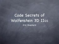
Super Hi-Res Screen Layout<br />
The <strong>Apple</strong> <strong>IIGS</strong> Super High-Res <strong>Graphics</strong><br />
screen operates in two modes of resolution:<br />
320x200 and 640x200. In the 320x200<br />
resolution each pixel is represented by 4 bits<br />
(thus there are two pixels per byte), in<br />
640x200 each pixel is represented by 2 bits (4<br />
pixels per byte). The size of the graphic<br />
screen is 32,000 bytes and is followed by 200<br />
scan line control bytes (one for each SHR<br />
Une), 56 bytes of unused space, and 512 bytes<br />
of palette information (for a total of 32,768<br />
bytes or 32K). The SHR graphics memory is<br />
located in memory bank SEt from memory<br />
locations $2000 to $9FFF.<br />
•<br />
Palette Data--><br />
SCB Data ------><br />
Super HI-Res Memory<br />
-::;-_c:• ~- _ -- 1f£;';:;1 :-~· . _. _·<br />
-<br />
--t9FFF•<br />
--t9Eee•<br />
--$90001<br />
Pixel Data ------><br />
The Super Hi-Res Pixels<br />
The pixel data for the Super Hi- Res screen is<br />
arranged in a linear fashion from $2000 to<br />
$9CFF in memory bank $E1. Each line on the<br />
Super Hi -Res screen is represented by 160 bytes<br />
in memory. In 320 mode each of the 320 pixels<br />
are 4 bits (totalling 160 bytes), in 640 mode<br />
each of 640 pixels are 2 bits (again, totalling 160<br />
bytes.) Line 0 on the SHR screen starts at<br />
$2000, Line 1 starts 160 bytes after Line 0, and<br />
so on, until Line 199, which ends at $9CFF.<br />
Each pixel value designates which color value<br />
will be used from the palettes located at $9EOO<br />
S9FFF.
Scan Line Control Bytes (SCBs)<br />
Each of the 200 vertical lines on the Super Hi<br />
Res screen has a single byte allocated to it.<br />
These bytes are known as Scan Une Control<br />
Bytes, or SCBs. SCBs regulate whether a line is<br />
in 320 or 640 mode, whether fill mode is<br />
Paoe 3<br />
operating for the line (320 mode only), if an<br />
interrupt is generated when the line is<br />
refreshed, and which of the 16 palettes will be<br />
used to represent the colors available to the<br />
pixels on the line.<br />
Scan Line Control Byte<br />
Palettes<br />
1<br />
1--ll..r..;t:::::::::::::::"RR~e~se;t.rved; do not modify<br />
.._____ Fill Mode, 1=on, O=off<br />
.._______ 1 =Generate interrupt, O=don't<br />
....-------1=640 mode, 0=320 mode<br />
There are 16 palettes (also known as color<br />
tables) that occupy the 512 byte space from<br />
$9EOO to $9FFF. Each palette has 16 entries (of<br />
two bytes each) that specify a color. The<br />
highest four bits are reserved, and the Red,<br />
Green, and Blue values are represented by<br />
four bits each. This allows 16 possible values<br />
for each of the three primary colors for a total<br />
['<br />
a e e I<br />
t9FC9 PAlette 1141<br />
t9FA9 Palette 1131 f1C<br />
$9F80 PAlette 1121 $1A<br />
t9F60 PAlette 1111 $18<br />
t9F40 PAlette 1101 $16<br />
$9F20 Palette 19• $14<br />
$9F00 Palette 18• $12<br />
t9EE0 PAlette 17• $10<br />
t9EC0 Palette 16• tE<br />
$9EA0 Palette 15• tC<br />
t9E80 Palette 14• $A<br />
t9E68 PAlette 13• $8<br />
t9E40 PAlette 12• $6<br />
0 $4<br />
e e I • $2<br />
><br />
of 4096 possible colors (16x16x16=4096). The<br />
value of each pixel is an offset into the palette<br />
being used tor its line. For example, if a pixel<br />
in 320 mode had a value of 4, the color of the<br />
pixel would depend on what the fifth color<br />
entry in the line's palette was set to (for<br />
example, if it was SFOO the pixel would be a<br />
bright red, $0FO bright green, $00F, blue ... ).<br />
o or •<br />
Color 114111<br />
Color 113111<br />
Color 112111<br />
Color 111•<br />
Color 119•<br />
Color 19•<br />
Color 18•<br />
17•<br />
16•<br />
15•<br />
14•<br />
13•<br />
12•<br />
11•<br />
iif!ITJiltJVIIII['•e• t u[? q 12ffi;. 1<br />
. Red (0-15) Blue (0-15)<br />
Green (0- t 5)<br />
Reserved, set to 0
Colors in 640 Mode<br />
The way colors and palettes operate in 640<br />
mode is different from 320 mode. In 640 mode<br />
each pixel is represented by only two bits,<br />
allowing 4 possible values. In order to access<br />
all 16 possible entries in the palette, each of<br />
the 4 pixels in a 640 mode pixel byte access a<br />
different set of 4 colors in the 16 color palette.<br />
Page 4<br />
The first pixel of the byte uses colors 8-11, the<br />
second pixel, colors 12-15, third pixel, colors 0-<br />
3 and fourth pixel colors 4-7. For example,<br />
pixel 47 on line 20 would be the fourth pixel in<br />
its byte. If this pixel has a value of 1, it would<br />
use the 5th color entry from the palette<br />
assigned to its line.<br />
Bit<br />
Pixel (640) t<br />
t ' 'I<br />
Pixel Value Palette Color<br />
3lll 0lll $011<br />
t• fl•<br />
2• $2•<br />
3• $3•<br />
4• 0• $4•<br />
1•<br />
z•<br />
J•<br />
-~·<br />
$6•<br />
$7•<br />
I!<br />
~4 I~ ,1~ II }.~.,<br />
Pixel Value Palette Color<br />
1• 0• $8•<br />
t•<br />
2• fA• ·~·<br />
3• •e•<br />
2• e• •c•<br />
1• tO•<br />
2• SE•<br />
3• $F•<br />
Dithering<br />
When in 640 mode, it is possible to achieve<br />
the effect of having 16 true colors. Because of<br />
the small width of the pixels, it is possible to<br />
alternate pixels of different colors in close<br />
proximity in order to fool the eye into<br />
Fill Mode<br />
Color- Fill mode is available in 320 mode only.<br />
By setting bit 5 of a line's SCB, fiJI mode is<br />
enabled for that line. When fill mode is<br />
active, a pixel value of 0 automatically takes<br />
on the color of the last pixel value ($1-SF)<br />
used before it on the right, so that:<br />
190499000~006049306000002000000•<br />
wtth fill mode off would become:<br />
111444444~~~6644336666662222222•<br />
with till mode on. Note that the first pixel<br />
value of a line must not be 0 (when fill mode<br />
IS on I, or a random color will result.<br />
perceiving a solid color that is a mix of the<br />
two alternating colors. For example,<br />
alternating blue and white gives a lighter<br />
shade of blue while blue and black give a<br />
darker shade.<br />
Turning SHR on and off<br />
Turning on:<br />
call QuickDraw II routine GratOn<br />
ldal SE1~82~•<br />
ora t~l eeeeee•<br />
st~l<br />
fr:l 92~•<br />
Turning off:<br />
call QuickDraw II routine GraiOtf<br />
!~i~ i~t~III!tl•
· Quagmirenc Animation Editor File Format<br />
Preliminary Format Description, revision 2<br />
Copyright 0 <strong>1992</strong> Nate Trost, All Rights Reserved<br />
Do not duplicate or distribute, Quagmire format subject to change prior to final release.<br />
Paoe 5<br />
+000 5 bytes I D<br />
'BWANI' -- ASCII ID. string (hi-bit clear)<br />
+005 2 bytes VERSION<br />
file format version number, hi byte major, low byte minor, e.g. $0100=1.13<br />
+007 1 byte TYPE<br />
type of animation data:<br />
255-2: reserved 1: 640 mode SHR 0: 320 mode SHR<br />
+008 1 byte COMPRESSION<br />
reserved<br />
+009 t byte PIXELSIZE<br />
size of each pixel in bits<br />
+010 WORD FLAGS<br />
bits 15-2:reserved<br />
bit 1: if set. all frames same height/width<br />
bit 0: H set, all frames have mask data following image data<br />
+012 WORD FRAMES<br />
number of frames in document<br />
+014 LONG FIRSTOFF<br />
offset from beginning of file to first frame record<br />
+018 LONG TABLEOFF<br />
offset from beginning of file to table of frame record offsets<br />
+022 LONG COLORTABLESIZE<br />
size of color table in bytes<br />
+026 See Above COLOR TABLE color table for document (for SHR, 32 byte in palette format)<br />
FRAME RECORDS<br />
+000 LONG NEXTOFF<br />
offset from beginning of frame record to next frame record, nil if last<br />
frame<br />
+004 WORD XSIZE<br />
XStze in words (number of pixels across/4)<br />
+006 WORD YSIZE<br />
YSize in pixels (height)<br />
+008 WORD FLAG<br />
Bits 15-1: reserved Bit 0: mask data included after image data<br />
+OOA LONG FRAMESIZEC<br />
If frame compressed, size of compressed frame data<br />
+OOE LONG FRAMESIZE<br />
Size of uncompressed frame data<br />
+012 8bytes USER<br />
8 byte reserved for whatever<br />
+OlA FRAMEDATA ...<br />
There is a table of frame offsets located in the document ... an offset to this table is located in<br />
the frame header, the table is made up of LONG values for each frame starting with the<br />
first... these values contain the offset from the beginning of the file to the beginning of the<br />
frame's record.
Drawing<br />
The act of drawing an object to the screen is actually a<br />
very simple matter. AD that drawing involves is the<br />
copying of pixel data from its buffer to the Super Hi<br />
Res screen memory. Before we can draw the shape, we<br />
have to know where to draw it.<br />
Calculating SHR Addresses<br />
We need a way to calculate a starting address from a<br />
pair of X/Y screen coordinates so we know where to<br />
start drawing. Here is the fonnula:<br />
320 Mode /640 Mode w I dithering: (Y • #$AO) +<br />
(X 1 S2) + #S2000 =starting address in SHR memoty<br />
640 Mode : (Y • #SAO) + (X I $4) + #S2000 = starting<br />
address in SHR memory<br />
• NOTES, each scan line is SAO (160 bytes) across and<br />
there are 2 pixels per byte when in 320 mode or 640 w I<br />
dithering and 4 pixels per byte when in 640 mode<br />
proper<br />
Now can we can figure the address, let's look at the<br />
work involved in drawing this simple shape:<br />
OOOOFFOOOO<br />
OOOFITFOOO<br />
OOFFFFFFOO<br />
OOF0770FOO<br />
OOF7007FOO<br />
OOOFFFFOOO<br />
OOOOFFOOOO<br />
This shape is 7 pixels high and 5 bytes across (we11<br />
assume 320 mode which makes the width 10 pixels<br />
across) for a total size of 35 bytes. Unfortunately, we<br />
just can't loop and copy 35 bytes to the SHR screen at<br />
our starting address. Why not? Because each tine of<br />
our image is only 5 bytes across, each S HR line is 160<br />
bytes across, we would end up with a long horizontal<br />
line that looks nothing like our image. What is the<br />
solution? We have to draw each Hne of the image to<br />
successive lines in SHR memory. This means we copy<br />
the 5 bytes to SHR memoty on the starting line, then<br />
we add 160 bytes to our SHR address to point it to the<br />
next line, and we add 5 bytes to our pointer to our<br />
shape and then copy the next 5 bytes_and so on and so<br />
forth until we have completed the job. That's an there<br />
is to drawin~<br />
Masking•<br />
Paoe 6<br />
.<br />
While the method we described above works, it has<br />
one noticable limitationMMthere is no way to screen<br />
out unwanted pixels in the source image, everything<br />
is copied. Also, there is no way to make parts of the ·<br />
image 'see-through', any existing 'background' pixel<br />
data is ovetWritten. In order to screen out unwanted<br />
pixels and allow the background to be presetved<br />
where these pixels are located, we need to use a<br />
technique called masking.<br />
In order to know which pixels to draw and which to<br />
ignore, we need a seperate pixel image called a mask.<br />
In our mask, SF pixels represent areas where we won't "<br />
copy a pixel and wiD preserve the background pixel<br />
and SO pixels represent areas where we wm copy the<br />
ptxel. Our mask for our image would look Hke this:<br />
IMAGE<br />
OOOOITOOOO<br />
OOOFFFFOOO<br />
OOE'E EE EE 00<br />
OOF0770FOO<br />
OOF7007FOO<br />
OOOFFFFOOO<br />
OOOOFFOOOO<br />
MASK<br />
ITFFOOFFFF<br />
FFFOOOOFFF<br />
FFOOOOOOFF<br />
FFOFOOFOFF<br />
FFOOFFOOFF<br />
FFFOOOOFFF<br />
FFFFOOFFFF<br />
In order to draw this image using the mask, we:<br />
1 LOAD existing pixel data in SHR memory<br />
2 AND this data with the corresponding mask data<br />
3 0 RAthe result with the cotTesponding image data<br />
'<br />
4 STORE the result back to SHR memory<br />
Here is what the process looks like going through<br />
drawing a Hne:<br />
LOAD existing data: 7788777444<br />
AND with mask: FFFFOOFFFF<br />
RESULT================7788007444<br />
ORA with image:<br />
OOOOFFOOOO<br />
RESULT================7788FF7444<br />
STORE back to memory!
'Erasing<br />
The other critical step in animating in 1mage<br />
is ERAS IN G. The shape that was drawn, in<br />
most cases, must be erased before the next<br />
frame is drawn. Erasing can mean either<br />
simply zeroing (or another value) over the<br />
drawn image on the SHR screen (usually done<br />
only if there is no background that needs to be<br />
preserved), or restoring the background data<br />
that was overwritten when the shape was<br />
drawn. Writing a routine to zero a block of<br />
memory is easy, restoring the background is<br />
slightly more complex.<br />
There are two basic ways to restore the<br />
background. The first is to copy the<br />
background data before it is overwritten<br />
WHILE IN THE DRAWING loop. The data is<br />
copied to a buffer of identical size of the shape<br />
being drawn. To restore the background, the<br />
data is simply copied back to the screen from<br />
the buffer at the exact location the drawing<br />
took place. The second method involves<br />
having another 32K buffer that acts as a<br />
background save buffer, where a clean copy of<br />
the background is always kept. Data is copied<br />
from the background save buffer to the SHR<br />
screen to restore the data overwritten by the<br />
image.<br />
Pave 7<br />
However, if you are using the local buffer<br />
method, you MUST erase the shapes in the<br />
opposite order you drew them, e.g.: Draw<br />
Circle, Draw Square, Draw Triangle .... Erase<br />
Triangle, Erase Square, Erase Circle.<br />
The reason for this reverse erasure order is<br />
that each of the shapes has their own buffer<br />
with their own copy of the background. If the<br />
square and the circle overlap, the square will<br />
copy the background to its buffer ... which will<br />
contain part of the circle image. The circle<br />
contains a perfectly clean copy since it was<br />
drawn first. If the circle were erased first and<br />
then the square, the square's buffer would<br />
bring back some the the circle image that<br />
should have been erased.<br />
Both techniques have advantages and<br />
disadvantages. The Background Save Buffer<br />
CBSB) method is faster in most cases, but needs<br />
another 32K, and can be awkward with<br />
anything other than a static, unchanging,<br />
background. The drawing buffer approach is<br />
slower because of the time needed to copy the<br />
data into the buffer (this is not needed with<br />
the BSB), but it a bit more flexible about nonstatJc<br />
backgrounds.<br />
Order<br />
Depending on the drawing/ erasing method<br />
being used, the order in which shapes are<br />
drawn and erased can be important. If you are<br />
using the Background Save Buffer to restore<br />
the background, it doesn't make any difference<br />
what order you draw I erase the shapes.
Shadowing<br />
In order to avoid the annoying effect of<br />
flicker when animating (especially with large<br />
and compex objects), a technique called<br />
shadowing can be brought to use. By clearing<br />
bit 3 of the SHADOW register at SC035,<br />
shadowing for the SHR memory is enabled.<br />
What this means is that the memory at<br />
$E1 I 2000-9FFF now has a counterpart at<br />
S01/2000-9FFF. When shadowing is on, any<br />
data written to $01/2000-9 FFF is automatically<br />
copied to $E1/2000-9FFF.<br />
The procedure of drawing using the shadowed<br />
screen is as follows:<br />
ERASE (if needed) previous shape on $01<br />
screen (with shadowing off)<br />
DRAW new shape on $01 screen (shadowing<br />
off)<br />
TURN on shadowing and copy affected data<br />
on $01 screen back onto self<br />
By using this process (drawing and erasing<br />
with shadowing off), it is impossible to see<br />
the shape when half-drawn or half-erased.<br />
When drawn I erased to the bank S01 screen<br />
with shadowing off, the data is not copied to<br />
the $e1 screen and therefore does not appear<br />
on the display. By turning shadowing on and<br />
recopying (loading and storing back onto<br />
itself) the data. you can quickly display the<br />
changes all at once.<br />
Stack Updates<br />
The fastest way to update the SHR screen is to<br />
map the stack and direct page onto the bank<br />
$01 screen and use an instruction cal1ed PEL<br />
By setting bits 5 and 4 in the State register at<br />
SC068, the stack and direct page are mapped to<br />
bank $01 instead of bank $00. PEl takes the<br />
two byte value found at a pair of direct page<br />
locations and pushes them on the stack, e.g.<br />
PEl $10 would take the value of direct page<br />
locations $10 and $11 and push them on the<br />
stack. By setting up the stack and having a<br />
Page a.<br />
long list of PEl's with th~ direct page set<br />
accordingly, it is possible to push data onto<br />
itself In only 7 cycles per word (6 tf the direct<br />
page is aligned on a page boundary). NOTE,<br />
interrupts MUST be disabled when the stack<br />
and direct page are mapped to bank $01!<br />
Paint Works Animations<br />
PaintWorks animation tiles (tiletype SC2)<br />
provide a simple method for saving fullscreen<br />
animations. The file format (never<br />
offtciaiiy specified) is as follows:<br />
+$0000-$7FFF - 32K screen image of<br />
the first frame<br />
+$8000-$8003 - Length of animation<br />
data blook<br />
+$8004-$8007 - Delay time per frame<br />
in 60th/second ticks<br />
+$8008-EOF - Animation data block<br />
The animation data block is made up of<br />
records that tell us how to modify each screen<br />
image for the next frame. There is a 4 byte<br />
value at the beginning that is an offset to the<br />
starting records, however, some animations<br />
do not have a valid value in this block so you<br />
should just skip over it to get to the first<br />
record. Each record four bytes, the first two<br />
bytes is an offset into a display screen, addtflg<br />
$2000 gives the address in SHR memory. The<br />
second word is the pixel data to store at the<br />
address specified. If the offset into SHR<br />
memory is zero, it means that this is the end<br />
of the frame.

![Converting Apple][ NTSC to VGA - KansasFest](https://img.yumpu.com/23761475/1/190x143/converting-apple-ntsc-to-vga-kansasfest.jpg?quality=85)