Proceedings
Proceedings
Proceedings

Create successful ePaper yourself
Turn your PDF publications into a flip-book with our unique Google optimized e-Paper software.
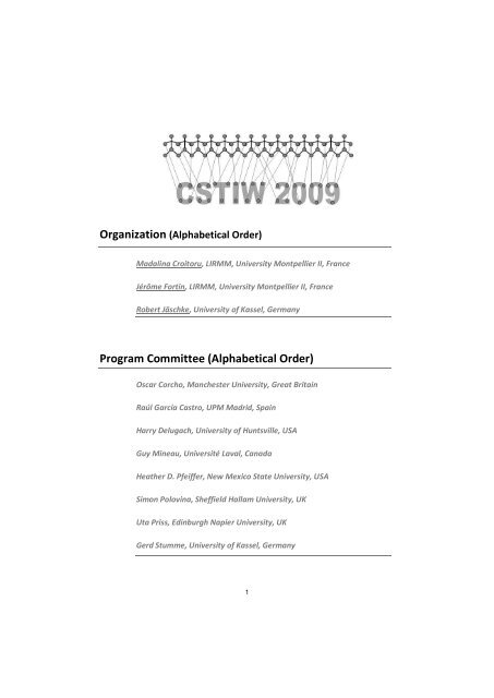
Organization (Alphabetical Order)<br />
Madalina Croitoru, LIRMM, University Montpellier II, France<br />
Jérôme Fortin, LIRMM, University Montpellier II, France<br />
Robert Jäschke, University of Kassel, Germany<br />
Program Committee (Alphabetical Order)<br />
Oscar Corcho, Manchester University, Great Britain<br />
Raúl García Castro, UPM Madrid, Spain<br />
Harry Delugach, University of Huntsville, USA<br />
Guy Mineau, Université Laval, Canada<br />
Heather D. Pfeiffer, New Mexico State University, USA<br />
Simon Polovina, Sheffield Hallam University, UK<br />
Uta Priss, Edinburgh Napier University, UK<br />
Gerd Stumme, University of Kassel, Germany<br />
1
The Fourth Conceptual Structures Tool Interoperability Workshop (CS-TIW<br />
2009) was held in Moscow, Russia on the 26th of July 2009, collocated with<br />
the 17th International Conference on Conceptual Structures (ICCS 2009)<br />
“Leveraging Semantic Technologies”. Information about the workshop is<br />
available at the webpage: http://www.kde.cs.uni-kassel.de/ws/cs-tiw2009.<br />
The title of this year’s workshop, “Vision and Applications” was chosen to<br />
emphasize the new challenges, problems and issues that have appeared in<br />
the context of knowledge representation that involve the visual<br />
manipulation of information by domain experts. Furthermore, such<br />
knowledge has to be manipulated with fast results within a logic based<br />
framework. In this context conceptual structure tools play a crucial role as<br />
their graph based foundations allow for (1) rigorous algorithmic reasoning<br />
and (2) user validation for both reasoning and representation. It is a unique<br />
environment for integrated research in discrete mathematics, human<br />
computer interaction, cognitive science and engineering.<br />
The workshop brought together researchers from diverse communities<br />
with the common goal of a fruitful discussion on the above mentioned<br />
interoperability issues by raising mutual awareness of ongoing research<br />
and existing technologies from which each community could benefit.<br />
We wish in full to express our appreciation to all the authors of submitted<br />
papers and to the members of the Program Committee for all their work and<br />
valuable comments.<br />
July 2009,<br />
Madalina Croitoru<br />
Jerome Fortin<br />
Robert Jäschke<br />
3
Table of Contents<br />
Integrated research environment “Graph Model Workshop” …………………………………………………… 7<br />
Victor Kokhov, Alexey Neznanov, Sergey Tkachenko<br />
The FcaFlint Software for Relation Algebra Operations on FCA Contexts …………………………………… 13<br />
Uta Priss<br />
Standard CGIF Interoperability in Amine ……………………………………………………………………………………… 24<br />
Adil Kabbaj, Ivan Launders and Simon Polovina<br />
A Commentary on Standardization in the Semantic Web,<br />
Common Logic and MultiAgent Systems ……………………………………………………………………………………… 33<br />
Doreen Mizzi, Wolfgang Browa, Jeremy Loke and Simon Polovina<br />
Data Conversion and Interoperability for FCA ……………………………………………………………………………… 42<br />
Simon Andrews<br />
Building Conceptual Graphs for Articles Abstracts in Digital Libraries …………………………………………. 50<br />
Michael. Y. Bogatyrev, Olga A. Mitrofanova, Vitaliy V. Tuhtin,<br />
Argumentation Map Generation with Conceptual Graphs: the Case for ESSENCE ………………………. 58<br />
Aldo de Moor, Jack Park, and Madalina Croitoru<br />
RDF to Conceptual Graphs Translations Calculating Shatterproof Transponds ……………………........ 70<br />
Jean Francois Baget , Michel Chein , Madalina Croitoru , Jerome Fortin , David<br />
Genest, Alain Gutierrez, Michel Leclere , Marie-Laure Mugnier, and Eric Salvat<br />
5
Integrated research environment<br />
“Graph Model Workshop”<br />
Victor Kokhov, Alexey Neznanov, Sergey Tkachenko<br />
State University - Higher School of Economics, Myasnitskaya 20,<br />
101000, Moscow, Russian Federation<br />
vkokhov@hse.ru, aneznanov@hse.ru, svt@graphmodel.com<br />
Abstract. Structured knowledge representation (e.g. conceptual graphs,<br />
semantic networks, etc.) needs to be supported by modern software. This is<br />
especially true for research fields where objects are modeled with graphs. We<br />
introduce an integrated research environment, "Graph Model Workshop", to<br />
support structural system analysis in such fields. This is a general-purpose<br />
software tool integrating a visual graph editor, an extensible set of graph<br />
problem solvers, a database, and modules for various kinds of analysis.<br />
Keywords: graph model, conceptual graph, structural analysis, software.<br />
1 Introduction<br />
There are not many tools with rich functionality in the field of knowledge<br />
representation and manipulation. Such systems must be built on a strong<br />
mathematical (logical, graph-theoretical, etc.) basis, modern human computer<br />
interaction principles and technological achievements. A new generation of tools must<br />
adopt modern standards and programming environments.<br />
Most of publicly available tools either are written in an interpretive language (Java<br />
in Amine toolkit [1]) or are designed only for editing and checking the conceptual<br />
graphs (CharGer CG drawer [2], ICom [3]) or may solve only specific problems or<br />
cannot are used by end users (Cogitant [4]).<br />
We introduce the integrated research environment “Graph Model Workshop” 1<br />
(GMW). It is a universal solution for computer-aided studies related to structural<br />
analysis of systems. Our principles: no Java, Python or other interpretive language in<br />
the core of system to improve the efficiency, a universal kernel of efficient graph<br />
functions and rich low-level DLL-API for functional extensibility, a maximal level of<br />
integration, a friendly user interface. The environment has been developed since<br />
1998. At this time we are working on the fourth version of this application [5].<br />
1<br />
Registered in ROSPATENT (CERTIFICATE 2005612847, issued in 2005)<br />
7
2 The Main Features of “Graph Model Workshop”<br />
Consider the following features of the system:<br />
Tight integration (fig. 1) of interactive and batch tools in a flexible unified<br />
modern multi-document user interface (fig. 2):<br />
o visual graph editor;<br />
o text processor;<br />
o database management systems for structural and relational data;<br />
o solvers for structural analysis problems;<br />
o components for experimentation and analysis of results.<br />
System Core<br />
Data<br />
Style Editor<br />
Text processor<br />
Core Results<br />
Analysis Tools<br />
Structural search<br />
engine<br />
Journal (Log)<br />
Visualizers<br />
Visual Graph Editor<br />
Structural DBMS<br />
Abstraction Layer<br />
Structural<br />
DBMS<br />
Experimentation<br />
Management<br />
Structural<br />
Database<br />
Database of<br />
results<br />
Plug-ins<br />
Solvers Solvers ...<br />
Solvers<br />
Fig. 1. GMW architecture<br />
Working with structures (graph models of systems), including digraphs with<br />
multiple weights (integer, float and string labels) on vertices and edges.<br />
The built-in editor of graph element styles designed to customize a visual<br />
appearance of structures for different theoretical and practical problem fields<br />
(for example, for formal concept analysis, group theory, organic chemistry,<br />
logistics or telecommunication).<br />
8
Automated multistage experimentation on structural databases with<br />
accumulation of results. Comparison, classification, ordering, clustering and<br />
visualization of results.<br />
Extendable structural search in databases, filtering of databases.<br />
Animated visualization of basic graph morphisms (automorphism, isomorphism,<br />
isomorphic embedding, etc), visualization of similarity graphs and graph<br />
fragments, visualization of graphs ordering and clustering.<br />
Import/export of graph databases in multiple formats. Ability to add new<br />
formats.<br />
The “PROVING GROUND” subsystem for performance assessment, testing<br />
and comparison of problem solvers.<br />
The open low-level and high-level application programming interfaces for<br />
adding new functions. Currently more than 370 GMW plug-ins have been<br />
developed.<br />
Learning and gaming components in educational versions of GMW (“STRIN”,<br />
“POLYGON” and others).<br />
Fig. 2. The GMW main window with a visual graph editor of the conceptual graph “Sample 1”<br />
2.1 Visual Editor of Structural Information<br />
GMW supports interactive editing of structures from various problem fields (for<br />
example: conceptual graphs, semantic networks, maps, molecular graphs). The editor<br />
provides all the standard functions: labeling, complex selection, fragment rotation,<br />
9
alignment and distribution of graph elements; unlimited undo, copy-paste capabilities,<br />
zooming. The editor is tightly integrated with manual and automated problem solvers.<br />
Customization of graph elements labels/weights is achieved by editing styles. A<br />
style of a vertex or an edge defines its visual appearance depending on its weights.<br />
2.2 Problem Solvers, Visualization and Animation<br />
GMW provides a plug-in system. There are open APIs for adding new plug-ins: lowlevel<br />
API for plug-ins in dynamic link libraries and several high-level APIs for exefiles.<br />
All solvers are implemented as plug-ins and can be easily managed and applied<br />
to the selected (interactive mode) or all (batch mode) structures in the open database.<br />
The core solvers include: identification and distinction analysis of structures<br />
(isomorphism, isomorphic embedding), maximal common fragment searching,<br />
transformation and decomposition of structures, ordering and classifying of structures<br />
by their complexity, similarity analysis of structures and their fragments, symmetry<br />
analysis.<br />
GMW has built-in visualization capabilities for results of several important<br />
problems. They include animated demonstration of graph layout building and graph<br />
morphisms. Results of graph renumbering, drawing, transformation, ordering and<br />
statistical analysis can be shown. These capabilities can be used by all the core<br />
components and plug-ins.<br />
2.3 Databases of Structural Information<br />
GMW works with structures organized in databases. Databases contain both<br />
structures and results of computational experiments. GMW offers searching,<br />
comparison and visualization of structures, as well as advanced tools for processing of<br />
results: statistical analysis, check for equality, comparative check, clustering, ordering<br />
and so on (fig. 3).<br />
2.4 Research Automation<br />
The user can define schemes of experiments containing a list of problem solvers to be<br />
performed repeatedly in batch mode for whole database or filter (fig. 4). Parameters<br />
for these schemes are either defined up front or entered at the runtime. The user also<br />
can conduct multistage experiment, when the results of the previous stage are used as<br />
input data for the next stage.<br />
2.5 “PROVING GROUND”<br />
GMW contains the original subsystem for the efficiency analysis of graph algorithms.<br />
It performs computational complexity estimation, comparison of efficiency and<br />
correctness of different problem solvers.<br />
10
Fig. 3. Stored results of computations and standard tools for their analysis<br />
Fig. 4. Last screen of master for running experimentation in batch mode<br />
11
2.6 GMW system requirements<br />
For using last version of GMW computer must meet following requirements:<br />
OS Windows 98/Me/NT/2000/XP/2003/Vista (Windows 2000 or higher is<br />
recommended).<br />
Intel Pentium class processor (Intel Pentium III / AMD Athlon 500MHz or<br />
faster are recommended).<br />
64 MB of free memory (256 MB are recommended for real experiments).<br />
14-60 MB on HDD (without bases of structural information).<br />
3 Conclusion<br />
GMW helps solving the following problems:<br />
Identification and finding distinctions of structures (canonization, isomorphism,<br />
homomorphism, isomorphic embedding, isomorphic intersection).<br />
Decomposition of structures into all labeled or nonisomorphic fragments with<br />
the specified constraints.<br />
Constrained generation and constructive enumeration of structures.<br />
Symmetry analysis (automorphism group processing).<br />
Finding the distinction of fragments placement in the structure topology.<br />
Ordering and classifying structures according to their complexity.<br />
Structural similarity analysis taking a placement of fragments into account.<br />
Exact or fuzzy searching in databases of structural information, graph mining.<br />
Automatic diagram drawing, finding optimal graph layouts.<br />
We see the further development of GMW in continuous expansion of the set of<br />
solvers, supported data formats (e.g. a full support of Conceptual Graph Interchange<br />
Format (CGIF)), and application fields without a loss of generality. The system core<br />
must be independent and as fast, isolated and robust as possible. As a result, an<br />
extensible toolkit with balanced characteristics will be built and successfully used in<br />
applied graph theory, group theory, formal concept analysis, structural linguistics,<br />
natural language processing.<br />
References<br />
1. Amine. A Java Open Source Platform for the Development of Intelligent Systems & Multi-<br />
Agent Systems, http://amine-platform.sourceforge.net/kora.htm<br />
2. CharGer. A Conceptual Graph Editor by Harry Delugach, http://charger.sourceforge.net<br />
3. Fillottrani, P. R., Franconi, E, Tessaris, S: The new ICOM Ontology Editor. <strong>Proceedings</strong> of<br />
the 2006 Int. Workshop on Description Logics, Lake District, UK, (2006)<br />
4. Cogitant – A Conceptual Graph Library, http://cogitant.sourceforge.net<br />
5. Kokhov, V.A., Neznanov, A.A., Tkachenko, S.V.: Progress of IRE “Graph Model<br />
Workshop” for research in field of structural analysis. <strong>Proceedings</strong> of Int. Conf.<br />
“Information tools and technologies”, pp. 45–49. Moscow, (2008)<br />
12
The FcaFlint Software for Relation Algebra Operations<br />
on FCA Contexts<br />
Uta Priss<br />
Edinburgh Napier University, School of Computing,<br />
www.upriss.org.uk<br />
Abstract. FcaFlint is a tool that implements context operations for FCA formal<br />
contexts. It is part of the FcaStone package. This paper provides an introduction<br />
to Relation Algebra operations as used by FcaFlint and discusses the commandline<br />
interface and implementation details of FcaFlint.<br />
1 Introduction<br />
FcaFlint 1 is a tool that implements context operations for FCA formal contexts. It can<br />
be used as a stand-alone tool (in which case the context must be formatted in the “.cxt”<br />
or “Burmeister” format), or it can be used in combination with FcaStone 2 (using any<br />
context format supported by FcaStone). The context operations are modelled using Relation<br />
Algebra (RA), which is an algebra that was invented by Peirce, Tarski and others<br />
and should not be confused with Codd’s Relational Algebra (RLA). Both RA and RLA<br />
provide a foundation for query languages. While RLA is normally used for many-valued<br />
tables in relational databases (using SQL), RA is suitable for binary matrices as used in<br />
Formal Concept Analysis (FCA). RLA is more expressive than RA, but RA has some<br />
interesting features for the use with formal contexts. Although some context operations<br />
(such as calculating dual contexts) are already provided by other FCA tools, as far as<br />
we know, none of the available tools implement a larger set of operations.<br />
This paper provides a brief introduction to RA (Sections 2 and 3) and discusses<br />
FcaFlint’s command-line options and the implementation of RA operations in FcaFlint<br />
(Section 4). The RA operations are described at a very basic level which assumes no<br />
prerequisite knowledge about matrix operations. The use of RA for FCA, in particular<br />
for linguistic applications has been described by Priss (2005), Priss (2006) and Priss<br />
& Old (2006). Those papers also provide more background and references which are<br />
omitted in this paper.<br />
There are many examples in the FCA literature where contexts are constructed from<br />
other contexts in a systematic manner, often involving RA operations (although RA<br />
may not be explicitly mentioned). Without having RA software, each application that<br />
uses RA operations requires special purpose code written for the application or manual<br />
editing of the formal contexts. With FcaFlint, RA context constructions (and also some<br />
additional non-RA constructions) can be much more easily derived. Some examples<br />
1 FcaFlint will be bundled with the next edition of FcaStone.<br />
2 http://fcastone.sourceforge.net/<br />
13
of using FcaFlint for context constructions are shown by Priss (2009). A very brief<br />
example of using RA as a query language is given at the end of Section 3 below. A<br />
more extended introduction to RA (which contains Sections 2 and 3 below, but has<br />
more details) can be found on-line 3 .<br />
2 Introduction to RA: Basic operations<br />
RA can be defined in a purely axiomatic fashion and can be used with many different<br />
applications. For this paper, only the application to Boolean matrices is of interest.<br />
Thus, the operations are defined with respect to Boolean (or binary) matrices, which<br />
are matrices that only contain 0s and 1s.<br />
Figure 1 shows some of the basic operations. Union I ∪ J, intersection I ∩ J, complement<br />
I and dual I d are applied coordinate-wise. For example, for union, a coordinate<br />
of the resulting matrix is 1, if a coordinate in the same position of any of the original<br />
matrices is 1. For intersection, the resulting matrix has a 1 in positions where both intersected<br />
matrices have a 1. Complementation converts 0s into 1s and 1s into 0s. The<br />
dual of a matrix is a mirror image of the original matrix, mirrored along the diagonal.<br />
There are three special matrices: the matrix one contains just 1s; nul contains just 0s;<br />
and dia, the identity matrix, contains 1s along the diagonal, 0s otherwise.<br />
Figure 2 shows the composition operation I ◦ J = K, which is a form of relational<br />
composition or Boolean matrix multiplication. If one conducts this operation by hand, it<br />
is a good idea to write the matrices in a schema as shown in the middle of Figure 2. The<br />
example on the right shows how an individual coordinate is calculated. The coordinate<br />
in the ith row and jth column is calculated by using the ith row of the left matrix and jth<br />
column of the right matrix. The individual coordinates are multiplied (using Boolean<br />
AND: 1 × 1 = 1; 1 × 0 = 0 × 1 = 0 × 0 = 0) and then added (using Boolean OR:<br />
1 + 1 = 1 + 0 = 0 + 1 = 1; 0 + 0 = 0).<br />
The bottom part of Figure 2 shows that non-square matrices can also be composed.<br />
But non-square matrices are not part of the usual RA definition. There are many ways<br />
to define RAs, abstractly or with respect to specific applications. The FCA-oriented RA<br />
definitions used in this paper are adapted from Priss (2006).<br />
Definition 1. A matrix-RA is an algebra (R, ∪, − , one, ◦, d , dia) where R is a set of<br />
square Boolean matrices of the same size; one is a matrix containing all 1s; dia is a<br />
matrix, which has 1s on the diagonal and 0s otherwise; ∪, − , ◦, d are the usual Boolean<br />
matrix operations. ∩ and nul are defined as I ∩ J := I ∪ J and nul := one.<br />
Non-square matrices do not form an RA, because these require:<br />
Special rules for non-square matrices:<br />
– For ∪ and ∩: the dimensions of the right matrix must be the same as the dimensions<br />
of the left matrix.<br />
3 An “Introduction to using Relation Algebra with FCA” can be downloaded from:<br />
http://www.upriss.org.uk/fca/relalg.html<br />
14
1 0 0<br />
1 1 0<br />
0 1 1<br />
0 0 0<br />
1 0 1<br />
0 1 0<br />
1 0 0<br />
1 1 1<br />
0 1 1<br />
1 0 0<br />
1 1 0<br />
0 1 1<br />
0 0 0<br />
1 0 1<br />
0 1 0<br />
0 0 0<br />
1 0 0<br />
0 1 0<br />
1 0 0<br />
0 1 1<br />
1 0 0<br />
d<br />
1 1 0<br />
1 1 0<br />
0 0 1<br />
1 1 0<br />
0 1 1<br />
0 1 1<br />
1 0 0<br />
0 1 1<br />
0 0 1<br />
one:<br />
1 1 1<br />
1 1 1<br />
1 1 1<br />
nul:<br />
0 0 0<br />
0 0 0<br />
0 0 0<br />
dia:<br />
1 0 0<br />
0 1 0<br />
0 0 1<br />
Fig. 1. Union, intersection, complement, dual matrix; the one, nul and dia matrices<br />
1 0 0<br />
1 1 0<br />
0 1 1<br />
0 0 0<br />
1 0 1<br />
0 1 0<br />
0 0 0<br />
1 0 1<br />
1 1 1<br />
0 0 0<br />
1 0 1<br />
0 1 0<br />
1*0 + 1*1 + 0*0 = 1<br />
0<br />
1<br />
0<br />
1 0 0 0 0 0<br />
1 1 0 1 0 1<br />
1 1 0 1<br />
0 1 1 1 1 1<br />
1 1 0<br />
0<br />
1<br />
0<br />
1<br />
0<br />
1<br />
0<br />
1 1 0<br />
0 0 0<br />
1 1 0<br />
0 0 0<br />
Fig. 2. Relational composition<br />
15
– For ◦: the number of columns in the left matrix must equal the number of rows in<br />
the right matrix.<br />
– dia, one and nul refer to sets of matrices whose actual dimensions depend on the<br />
matrices and operations with which they are used.<br />
These special rules mainly refer to the theoretical definition of matrix-RAs. It is<br />
possible to extend the definition of union, intersection and composition to matrices of<br />
arbitrary dimensions (if one is not concerned about creating an RA). But because there<br />
is more than one way to extend these definitions, it needs to be carefully considered<br />
which operations are meaningful for a particular application. This is further discussed<br />
in the next section.<br />
A further operation called “transitive closure” is sometimes defined. It should be<br />
noted that when the expressivity of RAs is discussed, transitive closure is not part of<br />
RA because it cannot be expressed by the basic RA operations. This is because although<br />
it only uses ∪ and ◦ in its definition, the dots (...) in its definition indicate some sort<br />
of infinity, which cannot be expressed by the other operations. (The proof for this is<br />
well-known and beyond this paper.)<br />
Figure 3 shows the transitive closure of the composition operation, which is defined<br />
as I trs := I ∪ I ◦ I ∪ I ◦ I ◦ I ∪ . . .. If the matrix I has 1s on the diagonal, I trs is<br />
calculated by composing I with itself until it does not change anymore (as shown in<br />
the top half of Figure 3). If the matrix I does not have all 1s on the diagonal, I is still<br />
composed with itself until it does not change anymore, but I and the results at each<br />
stage are unioned (as shown in the bottom half of Figure 3).<br />
3 Using RA with formal contexts<br />
Formal Concept Analysis (FCA) uses the notion of a formal context (G, M, I) which<br />
consists of a set G, a set M and a binary relation between G and M represented 4 by the<br />
Boolean matrix I. Figure 4 shows two formal contexts (K I and K J ). The elements of G<br />
are called (formal) objects; the elements of M are called (formal) attributes. RA should<br />
be applicable to the matrices of formal contexts, but because the matrices need not<br />
be square, this is not completely straightforward. Furthermore, the rows and columns<br />
in the matrices have interpretations: each row corresponds to an object; each column<br />
corresponds to an attribute. RA operations on formal contexts are only meaningful if<br />
they take these interpretations into consideration.<br />
In FCA, concept lattices are produced from the formal contexts. This is not relevant<br />
for this paper, but it should be pointed out that the RA operations on contexts in general<br />
do not translate into the same operations on lattices. For example, a union of contexts<br />
does not produce a union of lattices. Some RA operations may not have any useful<br />
applications for FCA.<br />
Because the use of RA operations for formal contexts is intuitive, but the construction<br />
of an RA for FCA is not completely straightforward, Priss (2006) provides two<br />
4 Because sets can be encoded as matrices, typewriter font (H) is used to denote sets, italics (H)<br />
is used for matrices (but not in the figures). The matrices of formal contexts are written with<br />
crosses instead of 1s.<br />
16
1 0 0<br />
1 1 0<br />
0 1 1<br />
1 0 0<br />
1 1 0<br />
0 1 1<br />
1 0 0<br />
1 1 0<br />
1 1 1<br />
1 0 0<br />
1 1 0<br />
1 1 1<br />
1 0 0<br />
1 1 0<br />
0 1 1<br />
1 0 0<br />
1 1 0<br />
1 1 1<br />
1 0 0<br />
1 1 0<br />
0 1 1<br />
trs<br />
1 0 0<br />
1 1 0<br />
1 1 1<br />
0 0 0<br />
1 0 0<br />
0 1 0<br />
0 0 0<br />
1 0 0<br />
0 1 0<br />
0 0 0<br />
0 0 0<br />
1 0 0<br />
0 0 0<br />
0 0 0<br />
1 0 0<br />
0 0 0<br />
1 0 0<br />
0 1 0<br />
0 0 0<br />
0 0 0<br />
0 0 0<br />
nul<br />
0 0 0<br />
1 0 0<br />
0 1 0<br />
trs<br />
0 0 0<br />
1 0 0<br />
0 1 0<br />
0 0 0<br />
0 0 0 nul<br />
1 0 0<br />
0 0 0<br />
1 0 0<br />
1 1 0<br />
Fig. 3. Transitive closure<br />
different suggestions to model this. The “unnamed perspective” is mostly of theoretical<br />
value because it makes it easy to form an RA, but is not practically useful. This perspective<br />
is called “unnamed” because objects and attributes are assigned to positions in<br />
a matrix, but their names are not used. Many FCA applications use not one, but many<br />
formal contexts which are often stored in a database. In the case of the unnamed perspective<br />
all objects and attributes of all of the contexts stored in a database are gathered<br />
into one linearly ordered set called an active domain A. The matrices of the contexts<br />
are transformed into |A|-dimensional matrices. It would not be practically useful to actually<br />
implement RA operations for FCA in this manner. Therefore this perspective is<br />
not further discussed in this paper 5 .<br />
The second suggestion is called the “named perspective” and describes a more practical<br />
approach that can be directly implemented in software, but which is more remote<br />
from the theoretical aspects of RAs. This perspective is discussed in the next section.<br />
The terms “named” and “unnamed” are chosen in analogy to their use in relational<br />
database theory.<br />
5 Further details on this perspective can be found in “Introduction to using Relation Algebra<br />
with FCA” available at: http://www.upriss.org.uk/fca/relalg.html<br />
17
3.1 The named perspective<br />
The “named perspective” uses names of rows and columns for all its matrices. In other<br />
words, the matrices used in this perspective all belong to formal contexts. Figure 4<br />
shows the union of contexts according to the named perspective. In this perspective,<br />
operations can be defined in a set-theoretic manner or in a matrix-based manner, where<br />
each row and column corresponds to a “named” object or attribute. The ordering of rows<br />
and columns can be changed while the names are explicit (top half of Figure 4), but not<br />
while matrices are used (bottom half of Figure 4). Definition 2 shows the set-theoretic<br />
definitions of context operations (according to Priss (2006)). Apart from complement<br />
and dual, these operations are different from Ganter & Wille’s (1999) definitions, although<br />
they are similar.<br />
K<br />
I<br />
a<br />
b<br />
c<br />
d<br />
e<br />
1<br />
x<br />
x<br />
2 3 4 5<br />
x<br />
x<br />
x x<br />
x<br />
{1, 2, 3, 4, 5, e}<br />
K<br />
I<br />
K<br />
J<br />
K J 1 2 e<br />
a x x<br />
b<br />
d<br />
x<br />
x<br />
x<br />
b<br />
c<br />
x<br />
x<br />
5 x<br />
d x x<br />
e<br />
5<br />
1<br />
2 3<br />
x<br />
x<br />
4 5<br />
x<br />
x<br />
e<br />
x<br />
{a, b, c, d, e, 5}<br />
1 1 o o o o<br />
o o 1 o o o<br />
o 1 o 1 o o<br />
1 o o o o o<br />
o o o o 1 o<br />
o o o o o o<br />
o o o o o o<br />
1 o o o o 1<br />
o o o o o o<br />
o 1 o o o o<br />
o o o o o o<br />
o 1 o o o o<br />
1 1 o o o o<br />
1 o 1 o o 1<br />
o 1 o 1 o o<br />
1 1 o o o o<br />
o o o o 1 o<br />
o 1 o o o o<br />
Fig. 4. Union in the named perspective<br />
Definition 2. For formal contexts K 1 := (G 1 , M 1 , I) and K 2 := (G 2 , M 2 , J), the following<br />
context operations are defined:<br />
K 1 ⊔ K 2 := (G 1 ∪ G 2 , M 1 ∪ M 2 , I ⊔ J) with gI ⊔ Jm :⇐⇒ gIm or gJm<br />
K 1 ⊓ K 2 := (G 1 ∪ G 2 , M 1 ∪ M 2 , I ⊓ J) with gI ⊓ Jm :⇐⇒ gIm and gJm<br />
K 1 ⋄ K 2 := (G 1 , M 2 , I ⋄ J) with gI ⋄ Jm :⇐⇒ ∃ n∈(M1∩G 2) : gIn and nJm<br />
K 1 := (G 1 , M 1 , I)<br />
K d 1 := (M 1 , G 1 , I d )<br />
The operations in Definition 2 can be used with all formal contexts. This is in contrast<br />
to the operations in Definition 3, which can only be applied in cases where special<br />
conditions are met (such as, G 1 = G 2 , M 1 = M 2 ).<br />
Definition 3. The following additional operations for formal contexts are defined for<br />
formal contexts K 1 := (G 1 , M 1 , I) and K 2 := (G 2 , M 2 , J):<br />
18
1. K 1 ∪ K 2 := K 1 ⊔ K 2 if G 1 = G 2 , M 1 = M 2<br />
2. K 1 ∩ K 2 := K 1 ⊓ K 2 if G 1 = G 2 , M 1 = M 2<br />
3. K 1 ◦ K 2 := K 1 ⋄ K 2 if M 1 = G 2<br />
Using Definition 3, ⊔, ⊓, ⋄ can be translated into matrix-based operations as shown<br />
below and in the bottom half of Figure 4 because Definition 3 fulfills the “Special rules<br />
for non-square matrices”. In contrast to the unnamed perspective, the matrices used here<br />
are of minimal dimensions (according to K ∗ 1 and K ∗ 2 below). The active domain A is<br />
used in this perspective as well but only in order to determine the order of the rows and<br />
columns: the objects and attributes corresponding to each matrix must be ordered in the<br />
same order as they appear in A.<br />
– K 1 ⊔ K 2 = K ∗ 1 ∪ K ∗ 2 with K ∗ 1 = (G 1 ∪ G 2 , M 1 ∪ M 2 , I); K ∗ 2 = (G 1 ∪ G 2 , M 1 ∪ M 2 , J).<br />
– K 1 ⊓ K 2 = K ∗ 1 ∩ K ∗ 2 with K ∗ 1 = (G 1 ∪ G 2 , M 1 ∪ M 2 , I); K ∗ 2 = (G 1 ∪ G 2 , M 1 ∪ M 2 , J).<br />
– K 1 ⋄ K 2 = K ∗ 1 ◦ K ∗ 2 with K ∗ 1 = (G 1 , M 1 ∪ G 2 , I); K ∗ 2 = (M 1 ∪ G 2 , M 2 , J).<br />
Figure 5 shows how basic FCA operations can be formed in the named perspective,<br />
calculating c ′ = {2, 4} and H ′ = {2} for H = {a, c}. The resulting algebraic structure<br />
is described in the next definition.<br />
Definition 4. A context algebraic structure (CAS) based on A is an algebra that implements<br />
the context operations from Definition 3. (See Priss (2006) for the complete<br />
definition.)<br />
A CAS is not an RA. There are no unique dia, one and nul matrices because these<br />
matrices need to change their dimensions and their sets of objects and attributes depending<br />
on what other matrices and operations they are used with. Furthermore, if negation<br />
is used in combination with composition, the results can be different from the ones in<br />
the unnamed perspective, which is a problem because the unnamed perspective does<br />
form an RA. There are ways to modify the CAS operations so that they yield an RA<br />
which is equivalent to the unnamed perspective, but this is complicated. Basically, CAS<br />
operations enlarge contexts as needed, by adding rows and columns. These rows and<br />
columns are usually filled with 0s, but if a context was previously negated once, they<br />
should be filled with 1s.<br />
It is possible to solve this by distinguishing the inside of a formal context (which<br />
consists of the relation between objects and attributes that is currently defined for the<br />
context) and the outside of the context (which collects conditions about potential elements<br />
from the active domain that might be added to the context at a later stage). Only<br />
the inside is stored as a matrix. The outside is stored as a set of conditions (e.g., “all 0”,<br />
“all 1”) without having a complete list of which elements belong to the outside.<br />
All contexts start out with their outside containing all 0s. Negation changes the<br />
outside to “all 1s”. Union and intersection may enlarge the inside, but the outside is<br />
still either “all 0s” or “all 1s”. Unfortunately, composition can change the outside of a<br />
context into conditions which are more complicated than “all 1” or “all 0”. Thus, it is<br />
still not easy to create an RA in this manner. But the complexity of these conditions<br />
increases slowly. For many applications, the outside conditions of the contexts will be<br />
simple or irrelevant.<br />
19
K<br />
I<br />
a<br />
b<br />
c<br />
d<br />
e<br />
1<br />
x<br />
x<br />
2 3<br />
x<br />
x<br />
x<br />
4 5<br />
x<br />
x<br />
1 1 0 0 0<br />
c’ = c<br />
d<br />
0 0 1 0 0<br />
I = (0 0 1 0 0)<br />
0 1 0 1 0<br />
= (0 1 0 1 0)<br />
1 0 0 0 0<br />
1<br />
0 0 0 0 1<br />
0<br />
H := { a, c} =<br />
1<br />
0<br />
0<br />
H’ = H<br />
d<br />
I = (1 0 1 0 0)<br />
1 1 0 0 0<br />
0 0 1 0 0<br />
0 1 0 1 0<br />
1 0 0 0 0<br />
0 0 0 0 1<br />
= (1 0 1 0 0)<br />
0 0 1 1 1<br />
1 1 0 1 1<br />
1 0 1 0 1<br />
0 1 1 1 1<br />
1 1 1 1 0<br />
= (1 0 1 1 1) = (0 1 0 0 0)<br />
Fig. 5. Basic FCA operations in the named perspective<br />
While it is beyond this paper to discuss applications in detail, Figure 6 provides<br />
a glimpse of how CAS can be used to model databases (Priss, 2005). In this example,<br />
a table with Employee data is translated into a relational schema, a many-valued<br />
context C Emp and value scales V ename and V eaddr . A corresponding binary matrix<br />
I Emp contains a 1 for every non-null value of C Emp and a 0 for every null value<br />
(in this case a one matrix). The bottom half of Figure 6 calculates the RA equivalent<br />
of the RLA query “select ename,eaddr from Emp where ename =<br />
’mary’ and eaddr = ’UK’”. In this modelling, mary is a row matrix indicating<br />
the position of “mary” in V ename ; similarly UK for V eaddr and ename, eaddr for<br />
I Emp . The result is a matrix that has 1s in the positions of “mary” and “UK”. The<br />
mv() function maps this onto a submatrix of C Emp with the values “mary” and “UK”.<br />
This example shows how RA can be used as a query language, although whether this is<br />
practically useful still needs to be determined. Other, definitely useful applications are<br />
discussed in Priss (2009).<br />
4 The implementation of RA operations in FcaFlint<br />
The FcaFlint software implements all of the RA operations discussed in this paper. In<br />
the first version, the operations are implemented mostly as matrix operations as described<br />
in Section 2. The only checks that are implemented refer to the “Special rules<br />
for non-square matrices”. (For example, the dimensions of one, dia, nul, dia are automatically<br />
determined where possible.) Furthermore, computing a dual matrix switches<br />
the object and attribute set and the result of composition selects the set of objects from<br />
the first matrix and the set of attributes from the second matrix. Otherwise, it is up to the<br />
user to make sure that the operations are meaningful with respect to formal contexts,<br />
i.e. that objects and attributes are ordered correspondingly and so on.<br />
FcaFlint also provides the non-RA operations apposition, subposition, equality and<br />
transitive closure of composition. The one, dia, nul, dia matrices can be used for ap-<br />
20
Employee table<br />
key ename eaddr<br />
e1<br />
e2<br />
e3<br />
e4<br />
paul<br />
mary<br />
carl<br />
sue<br />
UK<br />
UK<br />
USA<br />
USA<br />
a relational schema:<br />
tEmp<br />
e1<br />
e2<br />
e3<br />
e4<br />
Emp<br />
1<br />
1<br />
1<br />
1<br />
1<br />
eID<br />
1<br />
ename<br />
1<br />
eaddr<br />
1<br />
1<br />
2<br />
3<br />
4<br />
paul<br />
mary<br />
carl<br />
sue<br />
UK<br />
UK<br />
USA<br />
USA<br />
C<br />
Emp eID ename eaddr<br />
V<br />
ename<br />
paul mary carl sue<br />
V<br />
eaddr<br />
UK<br />
USA<br />
e1<br />
1<br />
paul<br />
UK<br />
e1<br />
1<br />
e1<br />
1<br />
e2<br />
2<br />
mary<br />
UK<br />
e2<br />
1<br />
e2<br />
1<br />
e3<br />
3<br />
carl<br />
USA<br />
e3<br />
1<br />
e3<br />
1<br />
e4<br />
4<br />
sue<br />
USA<br />
e4<br />
1<br />
e4<br />
1<br />
dia<br />
1 o o o<br />
o 1 o o<br />
o o 1 o<br />
o o o 1<br />
o<br />
1<br />
o<br />
o<br />
1 o<br />
1 o<br />
o 1<br />
o 1<br />
1<br />
o<br />
dia<br />
o<br />
1<br />
o<br />
o<br />
1<br />
1<br />
o<br />
o<br />
o o o o<br />
o 1 o o<br />
o o o o<br />
o o o o<br />
o o o o<br />
o 1 o o<br />
o o o o<br />
o o o o<br />
I Emp<br />
1 1 1<br />
1 1 1<br />
1 1 1<br />
1 1 1<br />
dia(ename,eaddr)<br />
o o o<br />
o 1 o<br />
o o 1<br />
o o o<br />
o 1 1<br />
o o o<br />
o o o<br />
mv<br />
o o o<br />
o 1 1<br />
o o o<br />
o o o<br />
o o o<br />
o mary UK<br />
o o o<br />
o o o<br />
Fig. 6. Calculating dia((V ename ◦ mary d ) ∩ (V eaddr ◦ UK d )) ◦ I Emp ◦ dia(ename d ∪ eaddr d )<br />
or: select ename,eaddr from Emp where ename=’mary’ and eaddr=’UK’<br />
21
position and composition with other matrices, but not in combination with each other.<br />
This is because in that case, the dimensions of the matrices would be unknown. The<br />
composition function also implements the (non-RA) operations of requiring at least n<br />
values to be shared in the composition.<br />
The operations are applied to a context stored in an input file (e.g. ex1.cxt) and the<br />
result is saved in a new file (e.g. output.cxt). The default format of the contexts is the<br />
Burmeister format, but in combination with FcaStone, any context format can be used<br />
that is supported by FcaStone. The RA operations are entered as functions as shown in<br />
Table 1. Table 2 shows examples of command-line usage of FcaFlint.<br />
FcaFlint function Meaning<br />
dual(ex1.cxt)<br />
Dual context<br />
invers(ex1.cxt) Invers context<br />
union(ex1.cxt, ex2.cxt) Union<br />
inters(ex1.cxt, ex2.cxt) Intersection<br />
compos(ex1.cxt, ex2.cxt) Relational composition<br />
appos(ex1.cxt, ex2.cxt) Apposition: ex1 on the left of ex2<br />
subpos(ex1.cxt, ex2.cxt) Subposition: ex2 underneath of ex1<br />
equal(ex1.cxt, ex2.cxt) Prints “Matrices are equal” or “Matrices are not equal”<br />
trans(ex1.cxt) Transitive closure of composition<br />
<br />
one<br />
<br />
nul<br />
<br />
dia<br />
<br />
dia<br />
Table 1. RA operations in FcaFlint<br />
FcaFlint command-line<br />
Meaning or result<br />
fcaflint “inters(ex1.cxt,invers((ex1.cxt))” output.cxt I ∩ I<br />
fcaflint “inters(ex1.cxt,compos(ex1.cxt,ex2.cxt))” output.cxt I ∩ (I ◦ J)<br />
fcaflint “equal(ex1.cxt,(dual(dual(ex1.cxt))))” output.cxt I = (I d ) d ,<br />
prints: “Matrices are equal”<br />
fcaflint “invers()” output.cxt<br />
prints: “Result is NUL matrix”<br />
fcaflint file.bat output.cxt<br />
Reads the operations from<br />
a batch file “file.bat”.<br />
Table 2. Examples of FcaFlint command-lines<br />
FcaFlint has been tested on matrices of sizes of up to 50×400. It returns reasonably<br />
fast results, with the exception of the transitive closure function, which should only be<br />
used for smaller matrices. It should be stressed that FcaFlint is aimed at expert users<br />
because using RA requires some expertise.<br />
22
The second version of FcaFlint intends to support RA operations according to the<br />
named perspective described in Section 3.1. In particular, it is fairly easy to implement<br />
checks for objects and attributes ensuring that they are compatible. The implementation<br />
of “inside” and “outside” conditions is slightly more complicated. The approach that<br />
is currently envisioned is to store simple conditions and to stop the program with a<br />
warning if the conditions are getting too complex. A warning would tell users that<br />
they need to manually check the sets of objects and attributes of their formal contexts<br />
and to verify whether the CAS operations that they are attempting to use are actually<br />
meaningful.<br />
Websites<br />
1. RA resources: http://www.upriss.org.uk/fca/relalg.html<br />
2. FCA website: http://www.upriss.org.uk/fca/fca.html<br />
References<br />
1. Ganter, Bernhard, & Wille, Rudolf (1999). Formal Concept Analysis. Mathematical Foundations.<br />
Berlin-Heidelberg-New York: Springer.<br />
2. Priss, U. (2005). Establishing connections between Formal Concept Analysis and Relational<br />
Databases. In: Dau; Mugnier; Stumme (eds.), Common Semantics for Sharing Knowledge:<br />
Contributions to ICCS 2005, p. 132-145.<br />
3. Priss, Uta (2006). An FCA interpretation of Relation Algebra. In: Missaoui; Schmidt (eds.),<br />
Formal Concept Analysis: 4th International Conference, ICFCA 2006, Springer Verlag, LNCS<br />
3874, p. 248-263.<br />
4. Priss, Uta; Old, L. John (2006). An application of relation algebra to lexical databases. In:<br />
Schaerfe, Hitzler, Ohrstrom (eds.), Conceptual Structures: Inspiration and Application, <strong>Proceedings</strong><br />
of the 14th International Conference on Conceptual Structures, ICCS’06, Springer<br />
Verlag, LNAI 4068, p. 388-400.<br />
5. Priss, Uta (2009). Relation Algebra Operations on Formal Contexts. In: <strong>Proceedings</strong> of the<br />
17th International Conference on Conceptual Structures, ICCS’09, Springer Verlag.<br />
23
Standard CGIF Interoperability in Amine<br />
Adil Kabbaj 1 , Ivan Launders 2 and Simon Polovina 3<br />
1 INSEA, Rabat, Morocco<br />
akabbaj@insea.ac.ma<br />
2 BT Global Services, PO Box 200, London, United Kingdom<br />
ivan.launders@bt.com<br />
3 Cultural, Communication & Computing Research Centre (CCRC)<br />
Sheffield Hallam University, Sheffield, United Kingdom<br />
s.polovina@shu.ac.uk<br />
Abstract. The adoption of standard CGIF by CG tools will enable<br />
interoperability between them to be achieved, and in turn lead to the<br />
interoperability between CG tools and other tools. The integration of ISO<br />
Common Logic’s standard CGIF notation in the Amine platform is presented. It<br />
also describes the first steps towards full interoperability between the Amine<br />
CG tool (through its Synergy component) and CharGer, a representative CG<br />
tool that supports similar interoperability and for process (or ‘active’)<br />
knowledge as well as declarative knowledge. N-adic relations are addressed as<br />
well as semantic compatibility across the two tools. The work remarks on the<br />
successes achieved, highlighting certain issues along the way, and offering a<br />
real impetus to achieve interoperability.<br />
1 Introduction<br />
The adoption of a standard that will enable the actual interoperability of Conceptual<br />
Graphs (CG) tools both between them and other tools has been a long-standing<br />
interest of this community. Through such means the CG tools themselves will become<br />
more widely adopted as there is less ‘lock in’ to the limitations of a particular tool,<br />
and in turn collectively bring the power of CG into wider arenas such as the Semantic<br />
Web. It is in this context that the standard for the Conceptual Graph Interchange<br />
Format (CGIF), a fully conformant dialect of ISO Common Logic (CL) [1], describes<br />
a set of transformation rules. CGIF is a representation for conceptual graphs intended<br />
for transmitting CG across networks and between IT systems that use different<br />
internal representations. The design goal for CGIF was to define a minimal abstract<br />
syntax and notation to achieve:<br />
• a proper foundation with translations to Knowledge Interchange Format (KIF)<br />
and permits extensions to be built upon;<br />
• a rapid interchange of CG between CG tools.<br />
24
Annex B [1] provides the CGIF syntax 1 and its mapping to CL. The Amine<br />
software platform [3,4] has accordingly been developed towards interoperability both<br />
in terms of syntax and semantics.<br />
2 Integrating Standard CGIF in Amine for Interoperability<br />
The integration of the Standard CGIF notation in Amine [3,4] (since Amine 6.0)<br />
involves many other integrations/additions (like a mapping for actors and a mapping<br />
for n-adic relations with n > 2), as follows.<br />
2.1 From “Amine CGIF” to Standard CGIF notation<br />
In previous versions, Amine adopted a proper subset of CGIF that we refer to “Amine<br />
CGIF”. There are certain differences between the Amine CGIF and Standard CGIF<br />
notation. Amongst them there is the use of the “pseudo-designator” in “Amine<br />
CGIF”. To explain, in Standard CGIF the coreferent has two functions:<br />
• It is used in the CGIF notation (and CG's Linear Form (LF) notation) to specify<br />
occurrences of the same concept in the same CG. Such a coreferent exists neither<br />
in the Display form, nor in the internal representation of the CG.<br />
• It is used to specify coreferent links between concepts that belong to embedded<br />
CG.<br />
The Pseudo-designator is used in Amine CGIF to play the first function of a<br />
coreferent. Instead of pseudo-designator, standard CGIF notation makes a direct use<br />
of a coreferent. For instance, instead of the pseudo-designator #1 in this example:<br />
[Work #1] [Person: Jane] [House : myHouse]<br />
(agnt #1 Jane) (near #1 myHouse) (ageOf Jane [Age = 30])<br />
(poss myHouse Jane)<br />
Standard CGIF notation [1] will use a coreferent:<br />
[Work *p] [Person: Jane] [House : myHouse]<br />
(agnt ?p Jane) (near ?p myHouse) (ageOf Jane [Age:30])<br />
(poss myHouse Jane)<br />
In Amine CGIF the designator and descriptor represents two different fields of a<br />
concept. In standard CGIF notation, coreferent, designator and descriptor share the<br />
same and one field; namely the field after the concept type. In Amine CGIF, a<br />
separator is used to differentiate between the designator and the descriptor. In<br />
standard CGIF notation, no separator is used to introduce and differentiate between<br />
the designator and the descriptor. The separator ":" is optional in Standard CGIF and<br />
there is great flexibility in ordering the coreferent, designator and descriptor; a<br />
coreferent can be placed before or after the designator and/or the descriptor.<br />
1<br />
In describing the syntax of CGIF, B.1.2 [1] uses the Extended Backus-Naur Form (EBNF)<br />
notation as referenced in ISO/IEC 14977:1996. However the classic Sowa [5] examples are<br />
used in the paper as referenced in the standard for CGIF [1].<br />
25
To assure backward compatibility with earlier versions of Amine 6.0 (i.e. that use<br />
just the Amine CGIF notation), Amine 6.0 adopts a CGIF syntax that integrates<br />
standard CGIF notation and Amine CGIF notation. A CG that was stored in Amine<br />
CGIF notation is thus still readable by Amine, but it will be reformatted into standard<br />
CGIF notation (i.e. a new save of the CG, in CGIF, will use standard CGIF notation).<br />
Here is the syntaxic grammar of a concept in Standard CGIF notation in Amine (a<br />
complete description of the grammar of Standard CGIF notation in Amine is provided<br />
in the Amine Web Site 2 ):<br />
Concept ::= "[" [Comment] Conc_Type<br />
[ParameterModes (generate in EndComment)] [CoReferent]<br />
[":"] [CoReferent] {Designator} [CoReferent] ["="] [Descriptor]<br />
[CoReferent] ["$" State (generate in EndComment)]<br />
["&" Point (generate in EndComment)] [EndComment] "]"<br />
Comment ::= "/*", {(character-"*") | ["*", (character-"/")]}, ["*"],<br />
"*/"<br />
EndComment ::= ";", {character - ("]" | ")")}<br />
Note that a concept can start with a comment and terminate with an end comment.<br />
A coreferent can be stated before or after the separator ":", before or after a<br />
designator, and before or after a descriptor. Separators ":" and "=" are optional.<br />
Parameter modes (appropriate to the Synergy component in Amine), States<br />
(appropriate to Synergy), and Point (appropriate to the CG display form) are also<br />
optional, and they can be specified inside the concept or in the end comment. Note<br />
also that the above syntaxic rule is used to define the syntax of concepts in both CGIF<br />
and LF notations. Thus, with Amine 6.0 we adopt the above syntaxic rule for the<br />
representation of concept in both LF and CGIF forms.<br />
Example #1 To illustrate, Sowa’s classical example ("John Goes to Boston by Bus")<br />
is shown in the LF notation, Standard CGIF, and Display Form (Figure 1):<br />
LF notation:<br />
[Go]-<br />
-instr->[Bus],<br />
-dest->[City :Boston ],<br />
-agnt->[Human :John ]<br />
Standard CGIF notation (without graphical information):<br />
[Go : *p1 ]<br />
(instr ?p1 [Bus]) (agnt ?p1 [Human :John]) (dest ?p1 [City :Boston])<br />
Standard CGIF notation (with graphical information):<br />
[Go : *p1 ; & 235 89]<br />
(instr ?p1 [Bus ; & 65 72]; (154 87)(235 97)(97 78)) (dest ?p1 [City<br />
:Boston ; & 299 164]; (283 135)(253 106)(334 164)) (agnt ?p1 [Human<br />
:John ; & 346 18]; (307 62)(255 89)(380 35))<br />
(The graphical information, for both concepts and relations, are specified in the<br />
EndComment.)<br />
2<br />
sourceforge.net/projects/amine-platform<br />
26
Example #2 An example proposed by Sowa to illustrate nested CG:<br />
LF notation:<br />
[Believe] –<br />
-expr->[Human : "Tom" ],<br />
-thme->[Proposition : [Want] –<br />
-expr->[Human : *x3 "Mary" ],<br />
-thme->[Situation : [Marry] –<br />
-agnt->[Woman : ?x3 ],<br />
-thme->[Sailor]<br />
]<br />
]<br />
Standard CGIF notation:<br />
[Believe : *p1 ]<br />
(expr ?p1 [Human : "Tom" ]) (thme ?p1 [Proposition : [Want : *p2 ]<br />
(expr ?p2 [Human : *x3 "Mary" ])<br />
(thme ?p2 [Situation : [Marry : *p3 ]<br />
(agnt ?p3 [Woman : ?x3 ]) (thme ?p3<br />
[Sailor])<br />
])<br />
])<br />
2.2 Standard CGIF notation, Actors and "active concepts"<br />
Concepts and relations capture declarative knowledge, but lack the capability for<br />
active or process knowledge. Actors 3 dynamically modify CG allowing active or<br />
process knowledge. Actors also provide the means to access external systems [2].<br />
Actors constitute a standard element in CG theory, like concepts and relations.<br />
Standard CGIF [1] provides a precise syntax for their representation. Amine adopts<br />
another perspective: a concept can represent a static or a dynamic, executable entity<br />
(operation, function, process, etc.). Thus, concepts represent both “static<br />
concepts” and “dynamic concepts” (i.e. Actors). Amine aims to allow the integration<br />
of its Synergy engine with an ontology in order to perform actor-like processing 4 .<br />
As Amine integrates Standard CGIF notation (as of Amine 6.0), we can provide a<br />
mapping between “CG with Actors” and “Amine CG (with dynamic concepts)”. Thus<br />
a CG with Actors that is formulated in standard CGIF notation can be translated to an<br />
Amine CG. Hence, interoperability between Amine and other tools that use Actors is<br />
now possible, such as between Amine and the CharGer 5 CG software that has<br />
extensive support for Actors. Figure 2 is an example of this mapping: Figure 2.a<br />
shows CharGer visual display of a CG with Actors. CharGer provides the possibility<br />
to save a CG (with Actors) in standard CGIF (Figure 2.b). The file produced by<br />
CharGer can then be read and reformulated by Amine (Figure 2.c). However, to<br />
activate/execute the CG by Amine, semantic compatibility is required, in addition to<br />
the common use of standard CGIF notation. This point is discussed next.<br />
3<br />
Not to be confused with Actors in the UML (www.uml.org)<br />
4<br />
More information on the Synergy language can be found via the Amine website, amineplatform.sourceforge.net<br />
5<br />
sourceforge.net/projects/charger<br />
27
Figure 1: Diagram Form of a CG (in Amine)<br />
Figure 2.a: CharGer diagram notation of a CG with Actors<br />
28
[ /* <br />
Number 99<br />
*/ Number: 99]<br />
...<br />
(/* <br />
minus */ minus 99 20 | 79)<br />
Figure 2.b: CharGer formulation of the above CG in Standard CGIF notation<br />
Figure 2.c: Amine’s reformulation of a CG with Actors through standard CGIF translation<br />
2.3 Standard CGIF, more than dyadic relations’ reformulation in Amine<br />
CG theory allows for conceptual relations that are more than dyadic, like the classical<br />
example of "Between" relation (Figure 3.a). Standard CGIF notation thus allows for<br />
the representation of more than dyadic relations. In Amine we consider dyadic<br />
relations only. However as Amine 6.0 integrates standard CGIF notation, we provide<br />
a mapping between “CG with more than dyadic relations” and “CG with dyadic<br />
relations only”: CG with more than dyadic relations formulated in standard CGIF<br />
notation is thus translated to CG with dyadic relations only. This mapping is based on<br />
the representation of the more than dyadic relation by a concept and dyadic relations<br />
(Figure 3). With this mapping, we can now affirm that Amine handles n-adic relations<br />
(where n > 2) thereby providing interoperability with tools that allow the use of n-adic<br />
relations. Figure 3 provides the example of the “Between” relation (with “Betw” as a<br />
synonym). Figure 3.b shows how Amine 6.0 provides the possibility to use more than<br />
dyadic relation, through standard CGIF notation. But as illustrated by the diagram<br />
(Figure 3.c), the relation is reformulated in terms of dyadic relations.<br />
29
Figure 3.a: Triadic relation<br />
Figure 3.b: Triadic relation in standard CGIF<br />
2.4 Semantic Compatibility<br />
Sometimes, interoperability requires semantic as well as syntaxic compatibility. With<br />
the integration of standard CGIF in Amine 6.0, it is now possible for Amine to open<br />
and read CG that are created by CharGer. But this may not be enough; to enable a CG<br />
in CharGer to be executable by Synergy (and vice-versa), semantic compatibility may<br />
also be required. Synergy therefore provides semantic compatibility by:<br />
• A mapping between CG with Actors (adopted by CharGer) and Amine CG with<br />
dynamic concepts (adopted by Amine);<br />
• A mapping between CharGer’s Actor identifiers with equivalent Synergy primitive<br />
operations. CharGer’s Actor identifiers are added in Amine as synonyms for<br />
identifiers of Synergy primitive operations. For instance “plus” is added as a<br />
synonym of “Add”, "minus as synonym of Sub", "multiply as synonym of Mul",<br />
etc.<br />
30
• To guarantee CG that represent arithmetic expressions created by Synergy can be<br />
opened and activated by CharGer, CharGer’s identifiers for arithmetic operations<br />
are preserved as the principal identifiers. Thus for instance, the Actor for addition<br />
will be expressed as [plus] instead of [Add].<br />
Figure 3.c: Reformulation of Triadic relation in Amine, through the CGIF translation<br />
With the implementation of semantic compatibility between CharGer and Synergy,<br />
most of CharGer’s CG can be activated and executed by Synergy. However since<br />
CharGer is equivalent to a subset of Synergy, certain CG with Amine/Synergy<br />
features cannot be activated by CharGer (such as Amine’s CG that contain control<br />
relations, or CGs with defined concept types).<br />
Thus, semantic compatibility remains partial because CharGer and Synergy<br />
consider a different semantic. Compatibility of the ontological level of the two tools is<br />
also partial: the ontology in CharGer corresponds to a type hierarchy, whilst ontology<br />
in Amine corresponds to a hierarchy of Conceptual Structures (Definition, Individual,<br />
Canon, Schema/Situation, Rule). Of course, a type can have no definition and no<br />
canon, and an individual can have no description. As the type hierarchy is a special<br />
case of Conceptual Structures hierarchy, any ontology used by CharGer can be<br />
automatically reformulated in Amine but not the inverse.<br />
Semantic interoperability is also affected due to certain forms of CG that are<br />
presently unsupported in Amine; for instance “null” is not allowed as a concept type,<br />
a monadic expression is not allowed as a concept type, a monadic relation is not<br />
allowed (unless it can be re-expressed as a dyadic relation), and cardinality is not<br />
considered. Some of these features may be integrated in future versions of Amine,<br />
depending on how important it is considered by the CG and wider community that<br />
such functionality should be supported.<br />
31
3 Concluding remarks<br />
We have described the integration of Standard CGIF notation in Amine, and the<br />
impact of this integration on the interoperability between Amine and, by using<br />
CharGer as one exemplar, other (CG) tools. It was most heartening to experience<br />
interoperability actually being accomplished through the adoption of standard CGIF.<br />
This actual experience was not discouraged by CharGer version 3.6, being the version<br />
we worked with in this exercise, being able to store a CG in standard CGIF but had no<br />
support for reading a CG written in standard CGIF. Rather, such issues can be<br />
overcome (for example in this case in the next version of CharGer), and that our<br />
experience will act as a key encouragement.<br />
We have also found ways to support semantic compatibility through our<br />
experiences with Amine and CharGer as we described, using Amine to recognise the<br />
differing semantics in another tool (CharGer) and adapt to it in a principled way.<br />
Of course we need continued effort from all sides to achieve heightened<br />
interoperability between Amine, CharGer and across all CG tools. By raising some of<br />
the issues involved in doing so, but at the same time demonstrating the success we<br />
have had, we have provided a real impetus to achieve the interoperability that the<br />
Conceptual Structures community ultimately desires.<br />
References<br />
1. International Standards Organisation (2007) International Standards for Business,<br />
Government and Society ISO/IEC 24707:2007 Information technology -- Common Logic<br />
(CL): a framework for a family of logic-based languages. Last accessed on 17 June 2009 at<br />
http://www.iso.org/iso/iso_catalogue/catalogue_tc/catalogue_detail.htm?csnumber=39175<br />
2. Delugach, Harry (2009) “A Practitioner’s Guide to Conceptual Graphs”, personal<br />
communication (available from the author)<br />
3. Kabbaj A., Development of Intelligent Systems and Multi-Agents Systems with Amine<br />
Platform, in 15th Int. Conf. on Conceptual Structures, ICCS'2006, Springer-Verlag, 2006.<br />
4. Kabbaj A., An overview of Amine, to appear in « Conceptual Structures in Practice:<br />
Inspiration and Applications », H. Schärfe, P. Hitzler (eds), Taylor and Francis Group, 2009.<br />
5. Sowa, J., (1984). ‘Conceptual structures: information processing in mind and machine’,<br />
Addison-Wesley.<br />
32
A Commentary on Standardization in the<br />
Semantic Web, Common Logic and MultiAgent<br />
Systems<br />
Doreen Mizzi, Wolfgang Browa, Jeremy Loke and Simon Polovina<br />
Department of Computing /Cultural, Communication & Computing Research Centre<br />
Sheffield Hallam University, Sheffield, United Kingdom<br />
{dmizzi, wbrowa}@hera.shu.ac.uk,{j.loke, s.polovina}@shu.ac.uk<br />
Abstract. Given the ubiquity of the Web, the Semantic Web (SW) offers<br />
MultiAgent Systems (MAS) a most wide-ranging platform by which<br />
they could intercommunicate. It can be argued however that MAS require<br />
levels of logic that the current Semantic Web has yet to provide.<br />
As ISO Common Logic (CL) ISO/IEC IS 24707:2007 provides a firstorder<br />
logic capability for MAS in an interoperable way, it seems natural<br />
to investigate how CL may itself integrate with the SW thus providing<br />
a more expressive means by which MAS can interoperate effectively<br />
across the SW. A commentary is accordingly presented on how this may<br />
be achieved. Whilst it notes that certain limitations remain to be addressed,<br />
the commentary proposes that standardising the SW with CL<br />
provides the vehicle by which MAS can achieve their potential.<br />
1 Introduction<br />
Since Tim Berners-Lee [1] publicly stated his vision of the Semantic Web (SW),<br />
there has been much work on devising Web technologies for explicitly annotating<br />
the existing data on the Web and for performing intelligent reasoning upon it.<br />
One potentially powerful area worthy of investigation is a SW in which software<br />
agents will be able to perform tasks and take decisions on behalf of humans.<br />
Given the ubiquity of the Web itself and developments in MultiAgent Systems<br />
(MAS) [34], the SW offers a global platform that MAS could be brought to bear<br />
and allow software agents to intercommunicate across this most wide-ranging<br />
arena.<br />
2 Common Logic<br />
The SW includes languages for ontologies and reasoning such as Resource Description<br />
Framework (RDF, www.w3.org/RDF), Web Ontology Language (OWL,<br />
www.w3.org/TR/owl-features), and TRIPLE (triple.semanticweb.org) [18, 2].<br />
Common Logic (CL) arose from two separate projects that were aimed at<br />
developing parallel ANSI standards for conceptual graphs and the Knowledge Interchange<br />
Format (KIF) [11]. These two projects eventually merged into a single<br />
33
ISO project, in order to develop a common abstract syntax for a family of logicbased<br />
languages. In fact, CL is now an established International Standard that<br />
provides a logic framework for the exchange of data and information amongst<br />
distinct computers on an open communication network. ISO/IEC 24707:2007<br />
[19] is the International Standard that describes a selection of logic languages<br />
that are directed towards this aim. This international standard ensures that the<br />
logic languages that it specifies all share their declarative semantics. Also, every<br />
logic language in the CL must be compliant with the generation of first-order<br />
logical sentences. All of this must be centred on sharing of data and information<br />
between incongruous computer systems. Hayes and Menzel [16] defined a very<br />
general model theory for CL, which Hayes and McBride [15] used to define the<br />
semantics for the languages Resource Description Framework (RDF) and Web<br />
Ontology Language (OWL). In fact, CL is not a single language that specifies<br />
a unique set of syntactic forms and hence it does not exclude any other forms<br />
of languages. CL allows for a number of so-called dialects to interoperate with<br />
the CL common abstract syntax. These dialects can have their own syntax, but<br />
must share uniform semantics, so that they can then be expressed using the CL<br />
abstract syntax.<br />
Three concrete syntaxes are specified in the standard:<br />
– CGIF - Conceptual Graph Interchange Format which is a text version of<br />
conceptual graphs.<br />
– CLIF - Common Logic Interchange Format whose syntax is based on KIF.<br />
– XCL - XML-based notation for Common Logic. This is intended to be a<br />
generic dialect for distributing CL content on any network that supports<br />
XML [19].<br />
As stated by Sowa[31], CL can also be utilized to map to and from controlled<br />
natural languages such as using CLCE (Common Logic Controlled English).<br />
3 CL, Ontologies and the SW<br />
An ever-increasing number of applications are benefiting from the use of ontologies<br />
as a way to achieve semantic interoperability among heterogeneous,<br />
distributed systems [32]. However, different interpretations may occur across<br />
different ontologies that lead to mismatches being made by MAS if they are to<br />
interoperate across them. One way forward would be to map the ontologies as<br />
suggested by Ding et al. [8]. However, this would result in the numerous combinations<br />
of mappings between each of the different ontologies.<br />
A more effective approach would be to map each ontology with CL, as it covers<br />
a larger set of first-order logic. As such it provides a general basis for dialects,<br />
applications or even networks to determine/establish conformance to CL syntax,<br />
hence a basis for meaning-preserving translation [24]. It also makes CLIF a<br />
genuine network logic, because CLIF texts retain their full meaning when transported<br />
across a network, archived, or freely combined with other CLIF texts<br />
(unlike the SW’s OWL-DL and GOFOL) [17]. The challenge arises when not<br />
34
all of the knowledge available in the ontology can be transferred back into CL<br />
as first-order logic and therefore this would filter out and reduce some of the<br />
information that can be transferred on to other mapped ontologies. The significance<br />
of this will depend on the importance of the non-transferable knowledge.<br />
It may also be possible to retain this knowledge as, say, comments; it would<br />
also explicate these differences and focus research energy onto how they may<br />
be in turn be interoperated. Success in this approach has been demonstrated<br />
with interoperating ontologies in the Amine conceptual graphs-based software<br />
(amine-platform.sourceforge.net) with the SW’s Protégé OWL (Web Ontology<br />
Language) software (protege.stanford.edu) [27].<br />
4 MAS Interoperability<br />
Central to the development of the SW is the concept of machine-readable transfers<br />
of information, marking a distinct move away from the current Web that<br />
was, as pointed out by MciLraith et al [23] ‘designed primarily for human interpretation<br />
and use’. We can of course note that Web Services are designed<br />
to provide interoperability between proprietary IT solutions, and have successfully<br />
contributed to the growth of electronic business and e-commerce solutions.<br />
However, MAS are designed to exist in a far more dynamic way. They need to<br />
develop their own interconnections and exist as self regulating open and decentralized<br />
applications. In this way, they would avoid the problems of traditional<br />
systems including ‘software reuse and discovery’ [28] while supporting interoperability<br />
by implementing semantic structure in a rigorous and standardized way.<br />
Fensel et al [9] state that the implementation of Web Services in an interoperable<br />
and machine-to-machine understandable manner would have a further impact on<br />
e-commerce and enterprise applications integrations. They identify this development<br />
as ‘a significant, if not the most important, factor in IT’. Web Services are<br />
being seen as the technological platform to deliver services to requesters. Agents<br />
on the other hand are intelligent systems that are trying to reason within the<br />
world they know. They can offer services but also make use of services provided<br />
elsewhere in order to reach their goals. Furthermore they could assemble, or ‘orchestrate’,<br />
a series of Web Services on the fly according to their autonomously<br />
decided aims at the time. An agent, for example, may assemble individual Web<br />
Services into the requisite business processes so that it can successfully negotiate<br />
a high-level business deal or transaction. Presently the orchestration (business<br />
or otherwise) remains a human endeavour [33].<br />
Meanwhile Leuf [21] draws attention to the fact that even ‘the lack of formal<br />
compatibility on syntactic as well as semantic levels greatly hinders the ability<br />
to accommodate domain interoperability’ [21]. Although the ability to rigorously<br />
share ontologies is key to ‘seamless integration’ [20], ‘fully automatic derivation<br />
of mappings is considered impossible as yet’ [5]. In the MAS environment, agents<br />
often may not be able to execute their programs properly as expected due to such<br />
compatibility issues. Correct interpretation of messages between different agents<br />
is essential for successful intercommunication between MAS environments. Gold-<br />
35
man et al [12] recommends that ‘multi-agent systems can be made more robust if<br />
they can autonomously overcome problems of miscoordination’. The same viewpoint<br />
is emphasized by Leuf [21], who stresses that ‘a major goal is to enable<br />
agent-based systems to interoperate with a high degree of autonomy, flexibility,<br />
and agility - without misunderstanding.’ As a result, this gives rise to the<br />
need for a more effective representation to describe and reason over the agent’s<br />
knowledge domain. As noted by Delugach [6] CL is the first standardized effort<br />
at developing techniques for interoperability between systems using various<br />
representations. Similarly, CL is supported by various existing commercial and<br />
open source software tools that can build and deploy ontologies. Such tools were<br />
designed to build ontologies compliant with the industry standards prior to the<br />
final CL standard [7].<br />
Also, Flores-Mendez [10] describe the work of standards in MAS. The Foundation<br />
for Intelligent Physical Agents (FIPA) have developed a series of MAS<br />
specifications like Agent Management and Agent Communication Language.<br />
FIPA targets to use a minimal framework to manage agents in an open environment.<br />
The Object Management Group (OMG) have proposed a model for<br />
agent technologies for the collaboration of agent components and agencies using<br />
interaction policies. These agencies are then in turn capable to support agent<br />
mobility, security and concurrent execution. The Knowledgeable Agent-oriented<br />
System (KAoS) approach addresses the standardization of open distributed architecture<br />
for software agents to facilitate agent implementations and messaging<br />
communication. Bearing commercial background, General Magic focuses on<br />
mobile agent technology in e-commerce allowing agents to move, connect, approve<br />
and interact in particular instances. Regardless of all these contributions,<br />
Flores-Mendez is of the view that practically not much effort has been realized<br />
in establishing a standard and acceptable definition of MAS architectures and<br />
frameworks. He states that this is possibly due to the belief that both the architectures<br />
and frameworks are required to match individual project requirements<br />
for the benefits of project efficiency. To allow for forward development of the<br />
SW with MAS, there should thus be stronger support for the integration and<br />
interoperability of MAS in this direction.<br />
There are also other critical technical issues in enabling software agents to<br />
deal with ontologies, such as the ability to achieve a seamless integration with<br />
existing Web browsers or user interface tools. To get around these problems,<br />
Blois et al [4] has recommended the SemantiCore framework. Another issue<br />
highlighted was that agents in MAS execute in a container separated from the<br />
containers of other MAS applications. Whilst work is in place to overcome this,<br />
such as Jade - a framework implemented in JAVA for MAS in providing JAVA<br />
classes for ontology manipulation), Blois et al [4] would still comment that no<br />
agents are specifically designed in support of the deployment of MAS to the SW.<br />
Like other agent technology developments, the Semantics MAS development also<br />
identifies security issues are remain to be resolved. This arises because security<br />
aspects are not taken into active consideration during the development cycle. As<br />
a result, security vulnerabilities are often exploited or detected only in the stage<br />
36
of program execution. The FAME Agent-oriented Modelling Language metamodel<br />
suggested by Beydoun et al [3], and other previously defined securityaware<br />
meta-models, help developers to take a conceptual approach to tackle<br />
security requirements of MAS as early as need be during the design stage of the<br />
development process. Another advantage would be the introduction of a common<br />
identification and validation process to register Agents and accord access rights,<br />
and the development and adoption of the WS-I standards in this area (www.wsi.org).<br />
Nonetheless first order logic based knowledge representation represents a<br />
powerful tool for machine-machine interaction. Claimed by Grimm et al [13] as<br />
‘the prevalent and single most important knowledge representation formalism....<br />
First-order logic captures some of the essence of human reasoning by providing a<br />
notion of logical consequence’. A computer agent is able to deduce and infer data<br />
from knowledge statements provided in a logical structure, replicating at least<br />
in part human domain expertise. Furthermore, by providing an abstract syntax<br />
CL removes the syntactic limitations of traditional first order logic, thus consistently<br />
facilitating translation between one language and another as we have<br />
stated. Using CL or one of its dialects as a content language will help facilitate<br />
the communication between the different agents in the system. CL dialects have<br />
been appropriately set up for the purpose of sharing semantics rather than syntax.<br />
As raised by Blois et al [4], a compatible or well-suited infrastructure is<br />
mandatory for the forward development of semantic MAS. An in all therefore,<br />
CL offers a most promising vehicle to MAS interoperability.<br />
5 Preciseness<br />
Given the overall usefulness of CL for MAS on the SW as discussed so far, we<br />
can now consider the preciseness of logic in achieving this aim. Sheth et al [29]<br />
among others subcategorize types of semantics into distinguishable categories<br />
based on how they are constructed and represented. They argue that formal<br />
semantics (information or knowledge represented in a highly structured way and<br />
in which structures can be combined to represent the meanings of other complex<br />
structures), and which would also apply to CL, has had a disproportionately high<br />
level of attention even within the SW. Focus is also required on what they view<br />
as the two other kinds; implicit semantics (semantics that rely on the analysis of<br />
unstructured texts with a loosely defined and less formal structure) and powerful<br />
semantics (the representation of imprecise, uncertain, partially true and/or<br />
approximate information). In essence, while CL provides a robust level of functionality<br />
for MAS interoperability it may, for a significant subtypes of data, not<br />
offer sufficient functionality for intelligent machine interaction to replace human<br />
domain expertise. Some domain knowledge possessed by human experts is intrinsically<br />
complex and may require the more expressive representations of powerful<br />
semantics that seeks to allow the representation of degree of membership and<br />
degree of certainty. Sheth et al [29]:<br />
37
‘In our opinion, for this vision [the SW] to become a reality, it will be necessary<br />
to go beyond RDFS and OWL, and work towards standardized formalisms<br />
that support powerful semantics.’<br />
Given that fully functional MAS must be able to process information that is<br />
not “precisely axiomatised”, subject to degrees or relation and degrees of accuracy<br />
then it must be concluded that CL alone is insufficient to fully realize the<br />
vision for the SW. There are still as yet “unidentified issues” to be discussed<br />
[6]. Notwithstanding a suitable model for “soft computing” that may embody<br />
known and unknown issues, the current situation still offers a robust way forward<br />
for MAS to interoperate. If that can be achieved without excluding future<br />
developments in these relevant fields then the vision of truly interoperable MAS<br />
on the SW can still continue to be realized.<br />
6 Further Considerations<br />
We can also note other aspects of CL, such as that it ‘also supports some features<br />
of higher order logics, such as quantifying over predicates specified in the domain<br />
of discourse’ [26]. This is highlighted by CL partial support the higher-order<br />
logics of Semantics of Business Vocabulary and Rules (SBVR). Section 10.2 of<br />
the SBVR specification ‘gives a partial mapping of SBVR concepts to OWL and<br />
to ISO Common Logic’ [22]. In some cases, the mapping is one-to-one, but in<br />
many others, a single SBVR concept is represented as a composition of multiple<br />
OWL or CL Constructs [22].<br />
Another dimension in the area of specialized digital libraries, where significant<br />
improvement has been made over the quality of the information as represented<br />
by the SW technologies versus the resources as retrieved by normal search<br />
engines [25]. This work also concluded that the SW can leverage the common<br />
data model and syntax to ensure the interoperability of resources which is also<br />
platform-independent. As a result there are added benefits for MAS to be had<br />
in the exchange and collaboration of digital libraries and corporate information<br />
repositories across the SW, and on which CL can be brought to bear.<br />
Lastly, no discussion on standardization is complete without reference to approaches<br />
that allow unstructured data to be accommodated, hence reducing the<br />
need for standards and recognising the Web is built upon myriad formats with<br />
various (lack of) structures each serving some individual, ill-compatible purpose.<br />
Embedding learning capabilities (e.g. Neural Net) technology that allow intelligent<br />
systems to learn like humans from their divergent surroundings provide<br />
another approach. Commercial companies like Autonomy (www.autonomy.com)<br />
employ such approaches that allows organisations to extract value from the<br />
myriad of different systems and information formats within their systems. Autonomy’s<br />
mixture of propriety Bayesian probability and Shannon theory, allows<br />
it to make some ‘sense’ of the information held in many different formats<br />
including voice, video and images. There are also open-source developments<br />
such as Unstructured Information Management applications (UIMA, incubator.apache.org/uima).<br />
Whilst we can envisage that unstructured data will be an<br />
38
ongoing feature of the Web, the thrust of the SW augmented with CL for the<br />
benefit of MAS remains. Rather we can expect the two approaches (structured<br />
and unstructured) to be complimentary activities that can benefit from each<br />
other. Structuring and thus automating knowledge allows humans to articulate<br />
their thinking, capture and interact with it through the productivity of computers<br />
i.e. conceptual structures, identified in the “Knowledge Architectures” theme<br />
of ICCS 2007 (www.iccs2007.info). Given also that conceptual structures in the<br />
form of conceptual graphs are core to CL, the need for CL on the SW for MAS<br />
remains undiminished.<br />
7 Concluding Remarks<br />
Even though relatively new as a standard, CL will aid towards achieving the<br />
much needed interoperability between the multitude of existing knowledge representations.<br />
Assisted by CL, intercommunication between MAS in on the global,<br />
most wide-ranging arena that the SW offers will be a key step in leading to the<br />
original vision as proposed by Tim Berners-Lee that the SW will evolve human<br />
knowledge [1]. Our work has helped identify the need, the key issues and direction<br />
in helping to realise that vision. Given the evidence and discussion that we<br />
have provided, we would support the view that additionally standardising the<br />
SW with CL provides the vehicle by which MAS can achieve their potential.<br />
Acknowledgements<br />
This work is based upon extensive research conducted by graduate students<br />
at Sheffield Hallam University, and we would sincerely like to acknowledge their<br />
valuable contributions that have culminated in this paper. We are also indebted<br />
to the anonymous reviewers of our originally submitted paper in guiding our<br />
thinking for this paper.<br />
References<br />
1. Berners-Lee, T. et al. (2001) The Semantic Web [online] Scientific American Magazine.<br />
Last accessed on 20th February, 2009 at http://www.sciam.com/.<br />
2. Berners-Lee, T. et al. (2008). N3Logic: A logical framework for the World Wide Web,<br />
Theory and Practise of Logic Programming, Vol. 8(3), p249-269; (AN 14185093).<br />
3. Beydoun, G. et al. (2008). A security-aware metamodel for multi-agent systems<br />
(MAS). Information and Software Technology Journal, Vol. 51(5) p 832-845.<br />
4. Blois, M. et al. (2008). Using Agents & Ontologies for Application Development on<br />
the Semantic Web. Computer Engineering Department, IME.<br />
5. Conroy et al. (2008) Ontology Mapping Through tagging. International Conference<br />
on Complex, Intelligent and Software Intensive Systems. Last accessed on 27th April<br />
2009 at http://ieeexplore.ieee.org.<br />
6. Delugach, H.S., (2007). Towards Conceptual Structures Interoperability using<br />
Common Logic. [online] University of Alabama. Last accessed 27 February<br />
2009 at:http://ftp.informatik.rwth-aachen.de/Publications/CEUR-WS/Vol-<br />
352/paper3.pdf.<br />
39
7. Denny, Michael (2004), Ontology Tools Survey, Revisited, [online]. Last accessed 27<br />
February 2009 at: http://www.xml.com/pub/a/2004/07/14/onto.html.<br />
8. Ding, Y. et al., (2001). Ontology management: survey, requirements and directions,<br />
IST Project IST-1999-10132 On-to-Knowledge [online]. Last accessed 18 March 2009<br />
at http://www.ontoknowledge.org/downl/del4.pdf.<br />
9. Fensel, Dieter et al., (2007). Enabling Semantic Web Services: The Web Service<br />
Modeling Ontology. Springer.<br />
10. Flores-Mendez, Roberto A. (1999). Towards a Standardization of Multi-Agent System<br />
Frameworks. University of Calgary. [online]. Last accessed 27 April 2009 at:<br />
http://www.acm.org/crossroads/xrds5-4/multiagent.html.<br />
11. Genesereth, M.R., and Fikes, R., (1992). Knowledge Interchange Format. Version<br />
3.0 Reference Manual, Computer Science Department, Stanford University, Stanford,<br />
CA.<br />
12. Goldman, C. et al., (2007). Learning to communicate in a decentralized environment.<br />
Autonomous Agents and Multi-Agent Systems, Vol. 15 (1), p47-90.<br />
13. Grimm et al. (2007) Knowledge Representation and Ontologies. Logic, Ontologies<br />
and Semantic Web Languages in Studer et al. (2007) Semantic Web Services:<br />
Concepts, Technology and Applications, pp51-106. Springer, Berlin. Last accessed<br />
on 27th April 2009 at http://www.aifb.uni-karlsruhe.de/WBS/phi/pub/kr-onto-<br />
07.pdf.<br />
14. Grosof, Benjamin, N., (2004) Representing e-commerce rules via situated courteous<br />
logic programs in RuleML. Electronic Commerce Research and Applications, Vol.<br />
3(2004), p2-20.<br />
15. Hayes, P. & McBride, B., (2003). RDF semantics, W3C Technical Report [online].<br />
Last accessed 17 February 2009 at: http://www.w3.org/TR/rdf-mt.<br />
16. Hayes, P. & Menzel, C., (2001). A semantics for the Knowledge Interchange Format.<br />
Proceeding of IJCAI 2001 Workshop on the IEEE Standard Upper Ontology, Seattle.<br />
17. Hayes, P. (2008) Using Common Logic. Mapping other KR technologies<br />
to CL, Eliminating dongles, The zero case. Presentation delivered<br />
at Semtech 2008 workshop. [online]. Last accessed 27 April 2009 at:<br />
www.ihmc.us/users/phayes/SemTech2008slides.ppt.<br />
18. Henze, N., et al., (2004) Reasoning and Ontologies for Personalized E-Learning in<br />
the Semantic Web. Educational Technology & Society, Vol. 7 (4), p82-97.<br />
19. International Standards Office, (2007). ISO 24707/2007 Information<br />
Technology - Common Logic (CL): a framework for a family of logicbased<br />
languages. [online] Geneva: ISO. Last accessed 27 April 2009:<br />
http://www.iso.org/iso/iso catalogue/catalogue tc/catalogue detail.htm?csnumber<br />
=39175.<br />
20. Lanzenberger, M. & Sampson, J., (2008). Making Ontologies Talk: Knowledge<br />
Interoperability in Semantic Web. IEEE intelligent systems journal, November/<br />
December 2008, p72.<br />
21. Leuf, B., (2006). The Semantic Web - Crafting Infrastructure for Agency. John<br />
Wiley & Sons, Ltd.<br />
22. Linehan, Mark H., SBVR Use Cases, IBM T.J. Watson Research<br />
Center. [online]. Last accessed 27 April 2009 at:<br />
http://www.aaai.org/Papers/Symposia/Spring/2008/SS-08-01/SS08-01-010.pdf.<br />
23. McIlraith, S. et al. (2001). Semantic Web Services. IEEE intelligent systems journal,<br />
March/ April 2001, p46.<br />
24. Menzel, C. (2008). Common Logic - Motivations and Some Gentle Theory. Presentation<br />
delivered at Semtech 2008 workshop. [online]. Last accessed 27 April 2009<br />
at: http://cl.tamu.edu/.<br />
40
25. Morales-del-Castillo J.M. et al., (2009). A Semantic Model of Selective Dissemination<br />
of Information for Digital Library. Information Technology & Library, American<br />
Library Association.<br />
26. Obitko, Marek. (2007).Ontologies and Semantic Web. [online]. Last accessed<br />
2 April 2009 at: http://www.obitko.com/tutorials/ontologies-semanticweb/introduction.html.<br />
27. Polovina, S. et al., (2009). A Practical Exploration of Ontology Interoperability. S.<br />
Rudolph, F. Dau, and S.O. Kuznetsov (Eds.): ICCS 2009, LNAI 5662, pp. 247256.<br />
Springer-Verlag, Berlin and Heidelberg.<br />
28. Sabou, M. and Pan, J., (2006). Towards semantically enhanced web service repositories.<br />
Journal of Web Semantics. Vol 5 (2), June 2007, p142-150 [online]. Available<br />
http://www.sciencedirect.com/.<br />
29. Sheth, A. et al., (2005), Semantics for the Semantic Web: The Implicit, the Formal<br />
and the Powerful. International Journal on Semantic Web and Information Systems.<br />
Idea Group Publishing.<br />
30. Semantics of Business Vocabulary and Business Rules (SBVR), v1.0, OMG<br />
Available Specification, January 2008 [online]. Last accessed 2 April 2009 at<br />
http://www.omg.org/docs/formal/08-01-02.pdf.<br />
31. Sowa, John F., (2008). VivoMind Intelligence, Inc. 4 March. [online]. Last accessed<br />
2 April 2009 at http://www.jfsowa.com/talks/semtech1.pdf.<br />
32. Tamma, V. et al., (2002). An ontology for automated negotiation. Proc. AA-<br />
MAS’2002 International Workshop on Ontologies in Agent Systems, 16-20 July,<br />
Bologna, Italy.<br />
33. Woods, D. (2006). Enterprise SOA. Beijing; Farnham: O’Reilly.<br />
34. Wooldridge, M. (2009). An Introduction to MultiAgent Systems (Second Edition),<br />
Wiley.<br />
41
Data Conversion and Interoperability for FCA<br />
Simon Andrews<br />
Communication and Computing Research Centre<br />
Faculty of Arts, Computing, Engineering and Sciences<br />
Sheffield Hallam University, Sheffield, UK<br />
s.andrews@shu.ac.uk<br />
Abstract. This paper proposes a tool that converts non-FCA format<br />
data files into an FCA format, thereby making a wide range of public<br />
data sets and data produced by non-FCA tools interoperable with FCA<br />
tools. This will also offer the power of FCA to a wider community of data<br />
analysts. A repository of converted data is also proposed, as a consistent<br />
resource of public data for analysis and for the testing, evaluation and<br />
comparison of FCA tools and algorithms.<br />
1 Introduction<br />
Most tools for Formal Concept Analysis require data to be in a particular format,<br />
usually representing a formal context and/or concept lattice. Unfortunately,<br />
most publicly available data sets, and most of the data produced by non-FCA<br />
applications, is not in this format. To make them interoperable with FCA tools,<br />
they need to be converted. Furthermore, there is a variety of data set formats<br />
and data types, each requiring different treatment. Converting data sets for FCA<br />
can be a time consuming and awkward task. A further problem arises in that a<br />
particular data set may be interpreted in different ways, resulting in inconsistent<br />
conversions. This can lead to different analyses of the same data and can make<br />
the comparison of FCA tools and algorithms more difficult. These problems have<br />
been pointed out by this author [2] and by Kuznetsov and Ob”edkov [5]:<br />
“We would like to propose the community to reach a consensus w.r.t. databases<br />
to be used as testbeds. Our idea is to consider two types of testbeds. On<br />
the one hand, some “classical” (well-recognised in data analysis community)<br />
databases should be used, with clearly defined scalings if they are many-valued.<br />
On the other hand, we propose to use “randomly generated contexts”. . . The<br />
community should specify particular type(s) of random context generator(s)<br />
that can be tuned by the choice of . . . parameters.”<br />
This paper, therefore, has two proposals to improve the interoperability and<br />
consistency of use of non-FCA format data sets:<br />
1. A ‘To-FCA Format’ Data Converter, that will provide FCA practitioners<br />
with an efficient and consistent means of converting a range of non-FCA<br />
data set formats into a format suitable for FCA.<br />
2. An FCA Data Repository, that will provide FCA practitioners with a resource<br />
of public data sets in FCA format.<br />
42
2 Data Conversion<br />
Public data set repositories, such as the UCI Machine Learning Repository [3]<br />
and Amazon Public Data Sets [1], provide a useful resource for FCA. Several<br />
data sets from the UCI Repository have become familiar to FCA. Four of these<br />
are listed in Table 1 and are useful to illustrate issues in data conversion. The<br />
table lists the name of the data set, its format, number of objects, number of<br />
attributes, the data type/s of the attributes and the number of attributes once<br />
converted into a formal context. Some of these have a question mark indicating<br />
that there are different interpretations possible. For example, the Mushroom data<br />
set has been quoted variously as having 125 [2], 119 [4] and 120 [9] attributes.<br />
Table 1. Some UCI Repository Data Sets<br />
Name Format Objs Atts Att Type FCA Atts<br />
Mushroom data only 8124 22 Categorical 125?<br />
Adult data only 48842 14 Categorical, 96?<br />
Integer<br />
MS Web DST Sparse 32711 294 N\A 294<br />
Internet Ads data only 3279 1558 Real, 1555?<br />
Relational<br />
There are several issues to consider when converting data sets into a formal<br />
context:<br />
Data Set Format Different ‘standard’ data set formats require different treatment.<br />
Some contain data values only, others include additional information, such<br />
as the names of the attributes or the classes of objects. Many contain data in tabular<br />
form, with rows representing objects and columns representing attributes.<br />
The type of the attribute (categorical, integer, real or relational) will determine<br />
the conversion technique required. Many data sets are multivariate, having a<br />
mixture of attribute types. Some data sets do not have a tabular format, such<br />
as the DST Sparse Data Format and Sparse ARFF, where relational data is<br />
represented by attribute/object pairs; clearly suitable for FCA, but requiring a<br />
different method of conversion. Similarly, RDF files [6] would require a different<br />
method of conversion, where an RDF subject becomes an FCA object. Databases<br />
are another important consideration; RDBMS data files would require a<br />
significantly different approach to the treatment of flat-file data.<br />
Categorical Attributes Categorical (many valued) attributes are the most<br />
common type and can be converted by creating a formal context attribute for<br />
each of the values. The attribute cap-surface, for example, in the Mushroom<br />
data set, has four values: fibrous, grooves, scaly and smooth. In a formal context,<br />
this becomes four attributes: cap-surface fibrous, cap-surface grooves, cap-<br />
43
surface scaly and cap-surface smooth. However, different interpretations are possible<br />
if an attribute has only two values; it may be said that not having one value<br />
implies having the other, thus leading to a single attribute in the formal context.<br />
This is particularly so if the values are opposites. For example, in the Mushroom<br />
data set, there is an attribute called bruises? that has values bruises and no.<br />
Should this be interpreted as a single attribute, bruises, or two: bruises? bruises<br />
and bruises no? If, for a particular attribute, there is no object with a particular<br />
value, or all objects have the same value, how should this be interpreted? In the<br />
Mushroom data set, for example, none of the mushrooms has a universal veil;<br />
all have a partial veil. Should the veil attribute be ignored or interpreted as one<br />
or two attributes?<br />
Other Attribute Types A table of Boolean values is used by some data sets<br />
to indicate the relationship between attributes and objects, such as the majority<br />
of the data in the Internet Ads data set. Such data can be translated, one-to-one,<br />
into a corresponding context. Attributes with integer or real types are less easily<br />
dealt with. Should they be ignored or should some form of scaling be used to<br />
create context attributes with ranges of values? Attributes that have free text<br />
values (a person’s address, for example) are the least convertible and will almost<br />
certainly be omitted in a conversion.<br />
Missing Values Many data sets contain missing values. Should they be treated<br />
as a ‘has not’ relationship or should objects with missing values be removed?<br />
Classes Some data sets contain classes of data. Should these be ignored in the<br />
conversion, treated as attributes, or should a separate context be created for<br />
each class?<br />
Clearly, a useful tool for data conversion must deal with all of these issues.<br />
2.1 A Conversion Example<br />
A simple example will help illustrate some of the issues outlined above, and<br />
visualise possible input and output files of an FCA data converter. Figure 1 is a<br />
miniature version of the UCI Mushroom data file, mushroom.data; a data only<br />
flat-file of comma separated values, and a format very suitable for input to an<br />
FCA data converter. The first column gives the mushroom class, the other four<br />
are mushroom attributes. Each is nominally valued in the following way:<br />
column 1 class: edible = e, poisonous = p<br />
column 2 bruises?: bruises = t, no = f<br />
column 3 gill-size: broad = b, narrow = n (missing value = ?)<br />
column 4 veil-type: partial = p, universal = u<br />
column 5 ring-number: none = n, one = o, two = t<br />
44
e,t,b,p,n<br />
e,t,n,p,t<br />
p,f,n,p,n<br />
e,t,?,p,o<br />
p,f,n,p,n<br />
Fig. 1. Miniature version of mushroom.data<br />
Figure 2 is an interpretation of the mushroom data as a formal context. The<br />
following decisions have been made in the interpretation:<br />
– The mushroom class is not used.<br />
– The attribute ‘bruises?’ is a single formal attribute.<br />
– All other attributes have a formal attribute for each of their possible values.<br />
Mushroom<br />
bruises<br />
gill-size-broad<br />
gill-size-narrow<br />
veil-type-partial<br />
veil-type-universal<br />
ring-number-none<br />
ring-number-one<br />
ring-number-two<br />
mushroom1 × × × ×<br />
mushroom2 × × × ×<br />
mushroom3 × × ×<br />
mushroom4 × × ×<br />
mushroom5 × × ×<br />
Fig. 2. Mushroom context<br />
Figure 3 is the Mushroom context in the Burmeister cxt file format, a common<br />
FCA context format used by a number of FCA tools and one that could be<br />
output from an FCA data converter. The ‘B’ at the start of the file possibly<br />
stands for ‘Burmeister’; it appears to be a tradition of the format! The numbers<br />
that follow are the number of objects and the number of attributes, respectively.<br />
The names of the objects and attributes are then listed, followed by the incidence<br />
vectors of the objects, consisting of dots and ‘X’s.<br />
How the object and attribute names are obtained will be a factor in the design<br />
of an FCA data converter, and how far this process can be automated will<br />
need to be considered.<br />
45
B<br />
5<br />
8<br />
mushroom1<br />
mushroom2<br />
mushroom3<br />
mushroom4<br />
mushroom5<br />
bruises<br />
gill-size-broad<br />
gill-size-narrow<br />
veil-type-partial<br />
veil-type-universal<br />
ring-number-none<br />
ring-number-one<br />
ring-number-two<br />
XX.X.X..<br />
X.XX...X<br />
..XX.X..<br />
X..X..X.<br />
..XX.X..<br />
Fig. 3. mushroom.cxt<br />
3 Proposal 1: A ‘To-FCA Format’ Data Converter<br />
Figure 4 is a simple, high-level view of the proposed ‘To-FCA Format’ data<br />
converter. The proposed output of the converter is a file in the Burmeister cxt<br />
format.<br />
Att/ Ob j<br />
Pa irs<br />
Convert<br />
Pa irs<br />
Sourc e<br />
Da ta<br />
File<br />
Determine<br />
Sourc e<br />
Forma t<br />
.cxt file<br />
(+ conversion log)<br />
Att/ Ob j<br />
Ta b le<br />
Determine<br />
Att Typ es<br />
Convert<br />
Attrib utes<br />
Fig. 4. Proposed ‘To-FCA’ Data Converter<br />
After selection of the source data file format, the main process is determined<br />
by whether the data is in the form of attribute/object pairs or in the form of<br />
a table. In the latter case, the tool must carry out the appropriate conversion<br />
depending on the type of each attribute. Information will be required by the tool,<br />
46
concerning the number and names of objects and attributes, the type of each<br />
attribute and its categories, if appropriate. This information may be obtained<br />
by the tool from the source data file, or from the user, depending on the source<br />
format, and will be output in a conversion log, along with information regarding<br />
decisions made in the conversion process, such as any original attributes not<br />
converted.<br />
There are a number of FCA context formats, other than cxt, used by a variety<br />
of FCA tools and applications. The data converter could be expanded to output<br />
these formats, too, but FcaStone 1 [7, 8], already exists that easily converts one<br />
commonly used FCA file type into another. The proposed data converter could<br />
integrate with FcaStone, making non-FCA format data interoperable with a<br />
much wider range of FCA tools and applications (Figure 5). In conjunction with<br />
Graphviz 2 , an open-source graph visualisation tool, FcaStone can produce a<br />
range of graph formats for the production of concept lattices, thus expanding<br />
further the range of FCA tools interoperable with the original data.<br />
Source<br />
Data<br />
File<br />
To-FCA<br />
Data<br />
Converter<br />
cxt File<br />
FcaStone<br />
(+ Graphiz)<br />
FCA Files:<br />
con, slf, bin.xml,<br />
tuples, csv, csc,<br />
cex, csx, fig, tex,<br />
dot, gml, gxl, svg,<br />
jpg, gif, png, ps, pdf<br />
FCA Tools<br />
& Applications<br />
Fig. 5. Possible Integration of ‘To-FCA’ Data Converter and FcaStone<br />
4 Proposal 2: An FCA Data Repository<br />
Figure 6 is a diagram of the proposed, web-based, FCA data repository. It is<br />
proposed that the data converter tool and FcaStone are incorporated into the<br />
repository allowing users to convert data sets as well as to access the stored<br />
converted data sets. Users will also be able to donate data sets. A converted data<br />
set will be stored along with, where possible, its original data file, information<br />
about the original data (probably from the original data source), a link back<br />
to the original data source, the conversion log, and FCA information, such as<br />
context density and number of concepts.<br />
To address needs outlined in the introduction of this paper, the repository<br />
will also provide access to stored random data and incorporate a random data<br />
1 FcaStone: http://fcastone.sourceforge.net<br />
2 Graphviz: http://www.graphviz.org<br />
47
FCA Data Repository<br />
To-FCA Data<br />
Converter<br />
+ FcaStone<br />
Data<br />
Source<br />
Data<br />
File<br />
.csv<br />
File<br />
Random<br />
Data<br />
Generator<br />
Data Set<br />
Original data file<br />
Data info.<br />
Source link<br />
Converted files<br />
Conversion log<br />
FCA info.<br />
Rnd Data Set<br />
csv file<br />
Data info.<br />
Converted files<br />
FCA info.<br />
Fig. 6. Proposed FCA Data Repository<br />
generator, the initial output of which will be a file of comma-separated object<br />
number, attribute number pairs. The csv file can then be converted into the<br />
required format. The user will be able to determine the number of attributes,<br />
number of objects and the density. It is proposed that the user will also select<br />
one of a small range of random number generator seeds; thus the same data set<br />
will be generated by any given seed/data parameters.<br />
In this way, the repository can act as a bench-marker for the comparison<br />
of tools and algorithms by providing citeable random data as well as converted<br />
‘real’ data sets.<br />
5 Development of the Proposals and Conclusion<br />
The To-FCA data converter will be developed as an open-source software. An<br />
initial prototype is under development, converting ‘vanilla’ data sets (such as<br />
the UCI Mushroom data set) and should be ready as a demonstrator tool in<br />
June/July 2009. A Link has been formed with the JISC Information Environment<br />
Demonstrator Project 3 to provide possible dissemination vehicles for the<br />
development. It is also hoped that participation in an ICCS 2009 workshop comparing<br />
the performance of FCA algorithms 4 will provide useful steering regarding<br />
data formats.<br />
The UCI Machine Learning Repository has kindly given the author permission<br />
to reformat and make their data sets available online. The FCA data<br />
3 JISC IE Demonstrator Project: http://www.jisc.ac.uk/whatwedo/programmes/<br />
reppres/iedemonstrator.aspx<br />
4 Comparing performance of FCA algorithms: http://iccs09.org/forum<br />
48
epository is likely to initially take the form of a web service offering a small<br />
selection of converted UCI data sets. The addition of random data sets and the<br />
incorporation of tools will be an incremental development. If data sets are to be<br />
encouraged from donors, a repository librarian will be required to validate them,<br />
ensuring that they are in required format and that the necessary (and verifiable)<br />
supporting information is provided.<br />
The final vision is of an interactive set of web-services, offering FCA tools<br />
interoperability with a wide range of data, providing a resource of useful collections<br />
of ‘real’ and random data sets in a wide variety of FCA context and lattice<br />
formats, and offering users the facility to create, convert and donate data sets of<br />
their own. Conversion between non-FCA and FCA formats will also open a way<br />
to the wider use of FCA, offering its power to those currently outside the FCA<br />
community.<br />
References<br />
1. Amazon Web Services: Public Data Sets on AWS [http://aws.amazon.com/<br />
publicdatasets/] (2009)<br />
2. Andrews, S.: In-Close, a Fast Algorithm for Computing Formal Concepts. To be<br />
presented at the Seventeenth International Conference on Conceptual Structures<br />
(2009).<br />
3. Asuncion, A., Newman, D. J.: UCI Machine Learning Repository<br />
[http://www.ics.uci.edu/∼mlearn/MLRepository.html]. Irvine, CA: University<br />
of California, School of Information and Computer Science (2007).<br />
4. Krajca, P., Outrata, J., Vychodil, V.: Parallel Recursive Algorithm for FCA. In:<br />
Belohlavek, R., Kuznetsov, S.O. (eds.), Proceeding of the Sixth International Conference<br />
on Concept Lattices and their Applications, pp. 71-82, Palacky University,<br />
Olomouc (2008).<br />
5. Kuznetsov, S.O., Ob”edkov, S.A.: Comparing Performance of Algorithms for Generating<br />
Concept Lattices. In: Journal of Experimental and Theoretical Artificial<br />
Intelligence, Vol. 14, pp. 189-216 (2002).<br />
6. Passin, T. B.: Explorer’s Guide to the Semantic Web. Manning Publications Co.,<br />
Greenwich, CT 06830, USA (2004).<br />
7. Priss, U.: FcaStone - FCA File Format and Interoperability Software. In: Croitoru,<br />
M., Jaschkë, R., Rudolph, S. (eds.), Conceptual Structures and the Web, <strong>Proceedings</strong><br />
of the Third Conceptual Structures and Tool Interoperability Workshop, pp. 33-43<br />
(2008).<br />
8. Priss, U: FCA Software Interoperability, In: Belohlavek, R., Kuznetsov, S. O. (eds.)<br />
Proceeding of the Sixth International Conference on Concept Lattices and Their<br />
Applications, pp. 133-144 (2008).<br />
9. Wang, J., Han, J., and Pei, J.: CLOSET+: searching for the best strategies for<br />
mining frequent closed itemsets. <strong>Proceedings</strong> of the Ninth ACM SIGKDD international<br />
Conference on Knowledge Discovery and Data Mining, pp. 236-245, ACM,<br />
New York (2003).<br />
49
Building Conceptual Graphs for Articles Abstracts in<br />
Digital Libraries<br />
Michael. Y. Bogatyrev 1 , Olga A. Mitrofanova 2 , Vitaliy V. Tuhtin 1 ,<br />
1<br />
Tula State University, Lenin ave 92, 300600 Tula, Russia<br />
2<br />
St. Petersburg State University, University emb. 11, 198134 St. Petersburg, Russia<br />
Abstract. An approach which is based on joining acquisition of conceptual<br />
graphs and analyzing them for further implementations is presented. The goal<br />
of conceptual graphs analysis is to find informative conceptual graphs for<br />
storing them in digital library. This analysis is based on learning links between<br />
sentences in abstracts by using two instruments: conceptual graphs clustering<br />
and passive voice grammar form as a possible pointer to the link between<br />
sentences. All results of acquisition of conceptual graphs and their clustering<br />
can be visually illustrated using modeling framework.<br />
Keywords: knowledge representation, conceptual graphs, clustering,<br />
visualization.<br />
1 Introduction<br />
In Digital Libraries conceptual graphs (CGs) [14], [15] become a competent part of<br />
stored data together with library texts. Conceptual graphs may serve as data for<br />
creating more general structures, for example ontologies, to form knowledge bases<br />
[11]. In this connection the problem of creating CGs automatically from library text is<br />
important. If CGs are acquired automatically then another problem of sufficient<br />
quantity of stored conceptual graphs appears. Actually, conceptual graph is a model<br />
of semantics of a sentence but not every sentence in library texts is informative for<br />
solving all these problems which use CGs.<br />
In this paper an approach which is based on joining acquisition of conceptual graphs<br />
and analyzing them for further implementations is presented.<br />
This approach is applied in digital library project devoted to store and process<br />
scientific papers. Conceptual graphs are acquired only from papers abstracts instead<br />
of processing the whole texts. This is based on the assumption that an abstract is short<br />
and clear essence of a paper.<br />
There are two instruments for analysis links between sentences in an abstract<br />
discussed in the paper. The first is based on the assumption that passive voice<br />
grammar form in a sentence often serves as a pointer to another sentence. Some<br />
peculiarities of conceptual graph acquisition from sentences in passive voice are<br />
illustrated. The second way of checking links between sentences is realized by<br />
conceptual graphs clustering.<br />
50
Both these ways are experimental and help an expert to select informative<br />
conceptual graphs for further implementations. Visualization of graphs and clusters is<br />
applied as crucial tool for making decision.<br />
2 Conceptual Graphs in Digital Library Project<br />
Digital libraries, unlike usual ones, are capable to present principally new functions to<br />
their users. Among them there is a function of knowledge representation when a user<br />
issuing a query to the library gets output as a structure of terms and notions related to<br />
that query. To support this function, a library must store and process some knowledge<br />
model. This high level model, for example ontology, represents knowledge inherent<br />
to library texts.<br />
We will have genuine knowledge representation system when its high level<br />
knowledge model – ontology - can be created or at least corrected from low level<br />
models – for example from conceptual graphs. This problem of building ontologies<br />
automatically is very complicated, not yet solved and may be could not be solved<br />
completely. As it is shown in [5], it is possible to go quite far in knowledge<br />
representation by using conceptual graphs. So on the way of creating ontologies,<br />
conceptual graph may serve as elementary start semantic model needed to generate<br />
next level models.<br />
Solutions of two standard problems of clustering and aggregation on conceptual<br />
graphs constitute principal foundation of creating next level models [2], [11]. Clusters<br />
of conceptual graphs correspond to possible topics of library texts and aggregated<br />
conceptual graphs represent a frame for library catalogue.<br />
We develop the digital library research project [1] where conceptual graphs are<br />
applied. It is a library of scientific papers collecting data from two sources: papers in<br />
English language from the CiteSeer portal [13] and papers in Russian language from<br />
the portal of RCDL conferences [6]. The project is being realized as an open<br />
framework containing subsystem of conceptual graph acquisition from text. It also<br />
contains subsystem for conceptual graphs clustering.<br />
2.1 Building conceptual graphs for abstracts<br />
There are many approaches to conceptual graph acquisition. One can find references<br />
to existing approaches in [4], [8], [16]. To summarize, we highlight the following<br />
points of general algorithm of conceptual graph acquisition.<br />
1. Lexical analysis of the source text for conceptual graph acquisition. Source<br />
text may be from natural language or domain specific text. If the last take<br />
place then domain lexicon is considered.<br />
2. Morphological analysis of the source text which includes identification,<br />
analysis and description of the structure of words in sentences. Word<br />
formation paradigm from certain language is applied. Here concepts of<br />
conceptual graph have been created.<br />
3. Semantic analysis. This point is mostly complicated and determines all<br />
variety of existing solutions. It is directed to create conceptual relations. As a<br />
51
ule, conceptual relations are not represented by words from analyzing<br />
sentence. So external resources (such as WerbNet and WordNet) have been<br />
applied in analysis.<br />
At first glance it seems that these three points of general algorithm can be applied to<br />
conceptual graph acquisition from a text in any language because they constitute<br />
standard grammar of language; in practice it is by no means so.<br />
To acquire conceptual graph from a sentence we use existing approaches to realize<br />
lexical, morphological and semantic analysis. We apply Semantic Roles Labelling [7]<br />
as the main instrument for building relations. Some special decisions were made for<br />
texts in Russian language and discussed below.<br />
For every article in the library only its abstract is processed for building conceptual<br />
graphs. This is reasonable since an abstract is short and clear essence of an article.<br />
2.1.1. Classifying abstracts<br />
It is evident that not every sentence in an abstract really contains actual information<br />
for processing in the library. So it is not needed to acquire conceptual graph from<br />
every sentence of an abstract. We classify all abstracts into two types: abstracts of<br />
declarative and narrative types. As a rule, declarative abstracts are short and contain<br />
weakly connected sentences. Oppositely, narrative abstracts are quite long and<br />
contain sequences of closely connected sentences.<br />
The most of real abstracts are declarative. Narrative abstracts are rare and may<br />
contain new ideas expounded sequentially. But namely narrative abstracts most<br />
probably have “useless” sentences. “Useless” sentences are often isolated, i.e.<br />
semantically not connected with others.<br />
To detect narrative abstracts we applied two criteria mentioned above: existing many<br />
sentences in the abstract – more than 6 (experimental result) and having high level of<br />
semantic similarity of sentences. We applied hierarchical clustering technique as<br />
experimental way to check links between sentences. The checking algorithm is the<br />
following.<br />
1. Find a long abstract.<br />
2. Acquire conceptual graphs from all sentences of an abstract.<br />
3. Build a clustering for conceptual graphs.<br />
4. Analyse the structure of clusters: CGs which constitute separate clusters are<br />
marked for further analysis as “useless”.<br />
The central problem in any clustering is a measure of similarity of clustering objects.<br />
We apply three similarity measures for conceptual graphs: two measures similar to<br />
Dice coefficients [2], [11] – conceptual and relational measures, and semantic<br />
measure similar to one applied in [16]. To calculate semantic measure we apply<br />
WordNet system for English texts.<br />
Figure 1 demonstrates clustering of conceptual graphs for two abstracts. One of them<br />
is the abstract in reference 9 which is definitely narrative having 11 sentences<br />
(numbers 0 – 10 on Figure 1) and being as a little story. The second abstract is very<br />
different from the first one and is consisted of only one sentence constituting its own<br />
cluster.<br />
52
Fig. 1. Clustering dendrogram of conceptual graphs for two abstracts having 11 and 1 sentences<br />
and using relative similarity measure.<br />
Clustering algorithm applied in the system uses special modified relative similarity<br />
measure based on the Dice coefficients. We detect narrativeness as specific nesting in<br />
clusters hierarchy shown on Figure 1. This kind of nesting with its slightly different<br />
visible variants is typical for all narrative abstracts. Nevertheless, clustering<br />
dendrogram could not directly help to find “useless” sentences in an abstract. For<br />
example the abstract from article [9] contains the sentence “At such extremes our<br />
intuition breaks down” (number 4 on the graph on Figure 1) which is not appropriate<br />
source for conceptual graph and was manually detected as “useless”.<br />
Using more detailed visualization which represents map of clusters we can find that<br />
this sentence is modeled by CG which has relations of attribute, agent. These<br />
relations occur in other CGs and therefore the first CG does not constitute the single<br />
cluster.<br />
53
Fig. 2. Map of clusters with statistics of concepts and relations. Notation n(m-k, …¸ s-r) means<br />
that on the n – th step of clustering the cluster contains k –th sentence from m-th abstract and so<br />
on up to r– th sentence from s-th abstract.<br />
2.1.2. Isolated concepts and multilingual passive voice problem<br />
Very often a text of a sentence in an abstract contains no direct useful information but<br />
a reference to other sentences. This feature is often realized grammatically by passive<br />
voice. There are two ways of building conceptual graph for a sentence in passive<br />
voice: create conceptual graph for equivalent sentence in active voice or create special<br />
tool for representing passive voice. Since a sentence in passive voice may be a pointer<br />
to external objects – concepts or conceptual graphs, - we have selected the second<br />
way.<br />
Working with passive voice in Russian and in English languages, one faces with<br />
many peculiarities of realizing passive voice in Russian language. English language,<br />
being more analytical than Russian language, has strict grammatical rules of<br />
expressing passive voice.<br />
Using our algorithm of conceptual graphs acquisition to English sentences in passive<br />
voice we applied the following solution: resulting conceptual graph has isolated<br />
concept corresponded to the verb “to be”. So the isolated concept “to be” serves as an<br />
indicator of passive voice.<br />
54
Unfortunately it is impossible to have such regular solution for texts in Russian<br />
language in passive voice. So we undertook special efforts to create algorithm of<br />
conceptual graphs acquisition for Russian sentences in passive voice. The instrument<br />
of Automated Lexical Analysis [10] was useful here. As a result an actor “passive”<br />
appears in the graphs denoting passive voice for Russian texts. Using visualization we<br />
can illustrate processing of sentences in passive voice by the following example.<br />
Consider two sentences about contemporary people: “Adam gave the apple to Eve”<br />
and “The apple was given to Eve by Adam”. Figures 3, 4 illustrate corresponding<br />
conceptual graphs in English and Russian languages.<br />
a) b)<br />
Fig. 3. Conceptual graphs for sentences in active (a) and passive (b) voice.<br />
Conceptual graph on Figure 3 - b) seems not correct because actually Adam serves as<br />
an instrument for delivering apples to Eve. In Russian variant Adam and Eve are<br />
relatives.<br />
For both languages we have special markers for passive voice – isolated concept “be”<br />
and an actor “passive”. They can be exploited not only visually but also in programs<br />
and help to select CGs for storing in digital library.<br />
55
a) b)<br />
Fig. 4. Conceptual graphs for sentences in active (a) and passive (b) voice for Russian texts.<br />
Translations: = to give, = an apple, = Eve, = Adam, =<br />
patience, = agent, = recipient, = genitive, = passive (actor).<br />
3 Conclusion<br />
We have presented approach to building conceptual graphs for abstracts of papers in<br />
digital library which uses analysis of abstract sentences. The goal of such analysis is<br />
to find informative conceptual graphs for storing them in digital library. We applied<br />
the framework for conceptual graphs acquisition and for clustering them. Presented<br />
results which illustrate proposed approach are preliminary. They may be expanded by<br />
new results of investigating various similarity measures in clustering problem and<br />
new results of learning semantic expressiveness of conceptual graphs against<br />
sentences they model.<br />
References<br />
1. Bogatyrev, M. Latov, V. Stolbovskaya, I.: Application of Conceptual Graphs in<br />
Digital Libraries. In: Digital libraries: Advanced Methods and Technologies, Digital<br />
Collections. <strong>Proceedings</strong> of the Ninth Russian National Research Conference -<br />
Pereslavl-Zalesskij: Pereslavl University. P.p. 109-115 (in Russian) ( 2007)<br />
2. Bogatyrev, M.Y. Tuhtin, V.V.: Solving Some Text Mining Problems with<br />
Conceptual Graphs. In: Digital libraries: Advanced Methods and Technologies,<br />
Digital Collections. <strong>Proceedings</strong> of the Tenth Russian National Research Conference<br />
RCDL'2008 Dubna, JINR p.p. 31-36. (in Russian). (2008).<br />
3. Bogatyrev, M.Y., Tuhtin, V.V.: Creating Conceptual Graphs as Elements of Semantic<br />
Texts Labeling. Computational Linguistics and Intellectual Technologies. Papers<br />
56
from the Annual International Conference “Dialogue 2009”. Issue 8 (15). P.p. 31-37<br />
(in Russian). (2009)<br />
4. Boytcheva, S. Dobrev, P. Angelova, G.: CGExtract: Towards Extraction of<br />
Conceptual Graphs from Controlled English. Lecture Notes in Computer Science <br />
2120, Springer Verlag. (2001).<br />
5. Chein, M., Mugnier, Marie-Laure: Graph-based Knowledge Representation.<br />
Computational Foundations of Conceptual Graphs. Series: Advanced Information and<br />
Knowledge Processing, Springer. (2008)<br />
6. Digital libraries: Advanced Methods and Technologies, Digital Collections. Digital<br />
Collection of <strong>Proceedings</strong>: http://rcdl.ru/<br />
7. Gildea D., Jurafsky D.: Automatic labeling of semantic roles. Computational<br />
Linguistics, 2002, v. 28, p.p. 245-288. (2002)<br />
8. Hensman, S, Dunnion, J.: Automatically building conceptual graphs using VerbNet<br />
and WordNet. In: <strong>Proceedings</strong> of the 3rd International Symposium on Information<br />
and Communication Technologies (ISICT), Las Vegas, June 16-18, 2004, pp.115-<br />
120. (2004).<br />
9. Horn, J, Goldberg, D.: Genetic Algorithm Difficulty and the Modality of Fitness<br />
Landscapes. In: Proc. of the Foundations of Genetic Algorithms (FOGA) 3<br />
Workshop, 1994 Estes Park, Colorado, USA.<br />
10. Mitrofanova, O. A., Zakharov V. P.: Automatic Analysis of Terminology in the<br />
Russian Text Corpus on Corpus Linguistics. Computational Linguistics and<br />
Intellectual Technologies. Papers from the Annual International Conference<br />
“Dialogue 2009”. Issue 8 (15) p.p. 321-328. (in Russian) . (2009).<br />
11. Montes-y-Gomez, M., Gelbukh, A., Lopez-Lopez, M.: Text Mining at Detail Level<br />
Using Conceptual Graphs. Lecture Notes In Computer Science; Vol. 2393. P. 122 –<br />
136. (2002)<br />
12. Rajman, M., Besançon, R.: Text Mining - Knowledge extraction from unstructured<br />
textual data In: Proc. of 6th Conference of International Federation of Classification<br />
Societies (IFCS-98), p.p. 473 – 480. (1998).<br />
13. Scientific Literature Digital Library and Search Engine: http://citeseer.ist.psu.edu/<br />
14. Sowa, J.F.: Conceptual Graphs for a Data Base Interface. IBM Journal of Research<br />
and Development 20(4): 336-357 (1976)<br />
15. Sowa, J.F.: Conceptual Structures: Information Processing in Mind and Machine.<br />
Addison-Wesley, London, UK (1984)<br />
16. Zhong, J., Zhu H., Li J., Yu Y.: Conceptual Graph Matching for Semantic Search.<br />
In: <strong>Proceedings</strong> of the 10th International Conference on Conceptual Structures:<br />
Integration and Interfaces, Springer-Verlag p.p. 92–106. (2002)<br />
57
Argumentation Map Generation with Conceptual<br />
Graphs:<br />
the Case for ESSENCE<br />
Aldo de Moor 1 , Jack Park 2 , and Madalina Croitoru 3<br />
1 CommunitySense, Cavaleriestraat 2, 5017 ET Tilburg, the Netherlands,<br />
ademoor@communitysense.nl<br />
2 Knowledge Media Institute, Open University, UK<br />
j.b.park@open.ac.uk<br />
3 LIRMM (CNRS and University Montpellier II)<br />
croitoru@lirmm.fr<br />
Abstract. Argumentation maps are visual representations of argumentation structures,<br />
making it possible to efficiently examine the cumulative results of protracted,<br />
distributed, and complex argumentation processes. Such visualizations<br />
can be useful to, for example, informally assess the status of public debates. Although<br />
the elicitation of argumentation maps is well supported, the support for<br />
the (1) analysis, (2) comparison, and (3) generation of maps relevant to particular<br />
stakeholders is still an open research problem. To develop such services,<br />
conceptual graph theory and tools can prove to be very useful. We analyze the argumentation<br />
needs of the ESSENCE (E-Science/Sensemaking/Climate Change)<br />
project, which aims to create useful argument maps to assess the current state<br />
of the global debate on climate change. We outline a public investigator service,<br />
which would allow policy makers, journalists, etc. to quickly zoom in on only<br />
those stakeholders, positions, and arguments they are interested in.<br />
Key words: argumentation maps, conceptual graphs, services<br />
1 Introduction<br />
Argumentation maps are visual representations of argumentation structures, making it<br />
possible to efficiently examine the cumulative results of often protracted, distributed,<br />
and complex argumentation processes. Such visualizations can be very useful to, for<br />
example, informally assess the status of public debates. They help give an overview of<br />
the issues, positions, arguments pro and contra positions and other arguments of the<br />
stakeholders involved.<br />
Although the elicitation of argumentation maps is well supported, support for the<br />
analysis, comparison, and generation of maps relevant to particular stakeholders is still<br />
an open research problem. Indeed, on the one hand the users of arguments are not<br />
necessarily the same as their creators. It is also very easy to get lost in the argument<br />
map space, especially when the maps grow in size, number, contributing authors, etc.<br />
Addressing such issues requires a careful pragmatic evaluation of collaborative technologies<br />
in their context of use, focusing on their relevance to the user community [5,<br />
58
7]. Fig. 1 outlines a conceptual model of this pragmatic evaluation of argumentation<br />
maps.<br />
m<br />
Fig. 1. Argumentation maps in their context of creation and use<br />
For instance, a policy maker in national government who is preparing new legislation<br />
about stricter carbon emission measures, may be especially interested in controversial<br />
issues, which are defined as those positions that business / environmental organizations<br />
have opposing arguments for / against. An argumentation map-based service<br />
should be able to present those parts of the overall climate change map which directly<br />
address this particular interest. Please note that the term “directly” is interpreted here<br />
in a somehow restrictive manner. In a first step we are interested in the immediate consequences<br />
and support arguments for a given issue that concerns the user. Once this<br />
service in place, it could be extended in order to include the transitive closure of pro /<br />
con arguments etc.<br />
To improve the relevance of argument maps, automated semantic analysis can be<br />
useful. Argumentation maps are in fact semantic networks of argument nodes connected<br />
by meaningful relations. To analyze dependencies between map parts and answer<br />
queries, this basic semantic network structure can provide a useful starting point.<br />
Please note that in this paper we will not analyze the “semantics” of the relations or how<br />
they interact amongst each other (transitive closure of the same type of relation, what<br />
a “contradictory” relation means etc.). Instead, we will regard the relations as binary<br />
relations with a given pre-defined order.<br />
Conceptual graph theory is a powerful formalism for knowledge representation and<br />
reasoning. Theory and tools can provide essential support especially in this application<br />
context. Intuitively this is due to the fact that Conceptual Graphs use graphs (a visual<br />
paradigm) for both representation and reasoning. This means that not only the main<br />
representational constructs of the language are graphs, but also that the operations that<br />
allow for reasoning (expressed in a subset of first order logic operations) are done via<br />
59
graph based operations. Of course, the type of inference needed in the context of argumentation<br />
maps and first order logic subsumption provided by Conceptual Graphs have<br />
to be accordingly joined together.<br />
To show how the worlds of argumentation maps and conceptual graphs can meet,<br />
we focus on addressing the argumentation needs of the ESSENCE (E-Science / Sensemaking<br />
/ Climate Change) project 4 . This project aims to create argument maps to help<br />
stakeholders assess the current state of the global debate on climate change. In order<br />
to do so, stakeholders must be able to view highly customized maps which are those<br />
selections from the overall map which should most directly relate to their current information<br />
needs. To this purpose, we propose an architecture of a service based on a<br />
system of interoperating argument mapping and conceptual graph tools that allow such<br />
stakeholder-relevant maps to be dynamically generated from the overall argument map<br />
having been created at a particular moment in time. This service can be the basis for a<br />
range of stakeholder-specific services such as for policy makers or investigative journalists.<br />
In Sect. 2, we explain the intuitive process behind the generation of relevant argumentation<br />
maps. Sect. 3 describes the role of conceptual graphs in providing the<br />
required service. Sect. 4 outlines an architecture of the ESSENCE argumentation map<br />
generator. We conclude the paper with a discussion and future directions of work.<br />
2 Argumentation Mapping Support: From Elicitation to<br />
Generation<br />
In this section, we introduce the ESSENCE case as a testbed for argumentation mapping<br />
support evaluation, and give a concrete example of the generation of relevant argumentation<br />
maps.<br />
2.1 The ESSENCE Case<br />
The ESSENCE project is the first major project that emerged out of the GlobalSensemaking<br />
Network 5 . It has a range of ambitious, but very important and interlinked goals<br />
[4]:<br />
– pilot software tools designed to help facilitate structured analysis and dialogue.<br />
Map, summarise and navigate science and policy arguments underpinning the issues<br />
that people care about and collaborate with the development teams who are<br />
shaping these tools to meet the complex, systemic challenges of the 21st Century.<br />
– develop a comprehensive, distilled, visual map of the issues, evidence, arguments<br />
and options facing the UN Climate Change Conference in Copenhagen,<br />
and being tackled by many other networks, which will be available for all to explore<br />
and enrich across the web.<br />
– build a definitive, public collective intelligence resource on the climate change<br />
debate.<br />
4 http://globalsensemaking.wik.is/ESSENCE<br />
5 http://www.globalsensemaking.net/<br />
60
– support dialogue that builds common ground, resolves conflict, and re-establishes<br />
trust<br />
In May 2009, a kickoff workshop was held at the Knowledge Media Institute of the<br />
Open University in Milton Keynes, UK 6 . It was decided that a demonstrator will be<br />
built to show proof of concept of the usefulness of the argumentation mapping tools for<br />
helping make sense of the global climate change debate. These tools, however, will not<br />
be applied in isolation, but as part of a system of tools in a well-defined usage context.<br />
This socio-technical system is to provide a useful service to stakeholders involved in<br />
the debate.<br />
Fig. 2. The DebateGraph Climate Change argumentation map<br />
To construct such a service, the initial focus is on the DebateGraph tool 7 , as using<br />
this tool already quite a comprehensive map of the most important risks, causes, and<br />
effects is being produced 8 , see Fig. 2. Furthermore, this map has already achieved considerable<br />
public visibility, as it has been embedded in the website of the UK quality<br />
newspaper The Independent 9 and as the DebateGraph tool has already been considered<br />
useful by the White House to map policy options relevant to the new U.S. administra-<br />
6 http://globalsensemaking.wik.is/ESSENCE/EVENTS/ESSENCE09_<br />
Workshop<br />
7 http://debategraph.org/<br />
8 http://debategraph.org/default.aspx?sig=610-610-2-0<br />
9 http://www.independent.co.uk/environment/climate-change/<br />
mapping-the-contours-of-climate-change-1640886.html<br />
61
tion 10 . As such, the maps produced through this tool are prime candidates for exploring<br />
relevant argumentation mapping functionalities in a realistic context of creation and<br />
use.<br />
2.2 Relevant Argument Map Generation: A Public Investigator Service<br />
Assuming that using Debategraph, over time many climate change-related maps are<br />
being created. These would comprise the ”reference map” currently being hosted at<br />
Debategraph and a number of related maps of particular interest to specific stakeholders.<br />
For example, one could be created by a EU policy making institute, one by the US<br />
government, one by a network of corporations interested in investigation carbon credit<br />
schemes, and so on. To be interoperable to at least some extent, all of these maps could<br />
be manually linked to relevant nodes of the reference map. However, to truly realize the<br />
policy making potential of these maps, relevant views need to be defined for map users.<br />
When generating these views, rather than interpreting the content of the nodes, we<br />
could automatically interpret the argumentation structure, which has a restricted, yet<br />
well-defined and powerful semantics. When defining this restricted semantics and the<br />
knowledge operations based on them, the focus would be on the stakeholders, as this is<br />
what interests policy makers: what are the relative positions of organizations X, Y, and<br />
Z on the web of issues, positions, and arguments?<br />
To illustrate what we mean, we introduce a ”Public Investigator” service. Assume<br />
there is an investigative journalist who is interested in being kept up to date about controversial<br />
issues, which in our argumentation structure semantics could be defined as:<br />
“all the immediate positions on issues of which there is at least one stakeholder<br />
(”protagonist” in Debategraph terms) of a business-type that gives either a pro<br />
or a con argument and at least one stakeholder of the NGO-type who gives<br />
an argument with the opposite argument-relation type (so, if the business<br />
stakeholder gives a pro-argument and the NGO-stakeholder a con-argument<br />
then we have a match, and thus a controversy, and vice versa).”<br />
The resulting positions plus the relevant argumentation parts with their associated<br />
stakeholders could then be presented in a simple web page, with clickable links to<br />
supporting contact information and documentation. An example of an argument map<br />
that should match with this query is given in Fig. 3.<br />
In the rest of the paper, we outline in broad strokes the theory behind and implementation<br />
of a service that could deliver such matches.<br />
3 Using Conceptual Graphs to Analyze Argumentation Map<br />
Semantics<br />
3.1 The IBIS formalism<br />
At the core of our argumentation semantics is the Issue-Based Information Systems<br />
(IBIS) paradigm. The IBIS formalism [6, 8] has been reduced to practice by Jeff Con-<br />
10 http://www.whitehouse.gov/blog/Open-Government-Brainstorm-<br />
Collaboration-in-Action/<br />
62
Fig. 3. An example of a matching argument map<br />
klin [3]; a small ontology that defines node types and inter-node relationships is available<br />
and used in ESSENCE platforms such as Compendium 11 , DebateGraph, and Deliberatorium<br />
12 . The principal nodes of interest are as follows:<br />
– Map - serves as an envelope that lends context to the other nodes, including map<br />
nodes.<br />
– Issue - provides a container to ask a question and to explain the question with<br />
further details. These nodes can be answered by issue nodes that refine the question,<br />
or by Position nodes which provide answers.<br />
– Position - provides a container to respond to a question with an answer, or to refine<br />
an earlier position.<br />
– Pro Argument - a node that presents an argument that supports a position, together<br />
with details that explain the argument.<br />
– Con Argument - a node that presents an argument that refutes a position, together<br />
with details that explain the argument.<br />
The node types we present represent an IBIS ontology that has been found to be<br />
common among the three IBIS platforms mentioned above. Each platform is capable<br />
of providing other node types, some of which may enter the common ontology. For<br />
instance, a Reference node is useful in documenting a position or argument, though<br />
citations can presently be included in the details.<br />
11 http://compendium.open.ac.uk/institute/<br />
12 http://18.36.1.44:8000/ci/login<br />
63
A typical IBIS conversation can begin with either an issue declaration, an opening<br />
question that sets the context for the remainder of the conversation, or the conversation<br />
can be opened with a topic for discussion, typically represented as a position node. An<br />
opening topic invites multiple issues to be raised. For instance, a conversation could<br />
begin with an issue such as ”What is the role of carbon dioxide in climate change?”,<br />
which defines a narrow context; a different conversation could simply begin by stating<br />
that ”Climate Change” is the topic of the conversation, which would invite questions<br />
along the lines of causes, consequences, and so forth.<br />
In a typical IBIS conversation in DebateGraph, IBIS statements take the form of<br />
short natural language sentences. The IBIS formalism adds context to those statements<br />
through the structure the conversation takes.<br />
3.2 The CG formalism<br />
Conceptual Graphs were introduced by Sowa (cf. [9, 10] ) as a diagrammatic system of<br />
logic with the purpose “to express meaning in a form that is logically precise, humanly<br />
readable, and computationally tractable”. In this paper we use the term “Conceptual<br />
Graphs” to denote the family of formalisms rooted in Sowa’s work and then enriched<br />
and further developed with a graph-based approach in [2].<br />
Conceptual Graphs encoded knowledge as graphs and thus can be visualized in a<br />
natural way:<br />
– The vocabulary, which can be seen as a basic ontology, is composed of hierarchies<br />
of concepts and relations. These hierarchies can be visualized by their Hasse diagram,<br />
the usual way of drawing a partial order.<br />
– All other kinds of knowledge are based on the representation of entities and their<br />
relationships. This representation is encoded by a labeled graph, with two kinds<br />
of nodes, respectively corresponding to entities and relations. Edges link an entity<br />
node to a relation node. These nodes are labeled by elements of the vocabulary.<br />
The vocabulary is composed of two partially ordered sets: a set of concepts and a<br />
set of relations of any arity (the arity is the number of arguments of the relation). The<br />
partial order represents a specialization relation: t ′ ≤ t is read as “t ′ is a specialization<br />
of t”. If t and t ′ are concepts, t ′ ≤ t means that “every instance of the concept t ′ is<br />
also an instance of the concept t”. If t and t ′ are relations, then these relations have the<br />
same arity, say k, and t ′ ≤ t means that “if t ′ holds between k entities, then t also holds<br />
between these k entities”).<br />
A basic graph (BG) is a bipartite graph: one class of nodes, called concept nodes,<br />
represents entities and the other, called relation nodes represents relationships between<br />
these entities or properties of them. A concept node is labeled by a couple t : m where<br />
t is a concept (and more generally, a list of concepts) and m is called the marker of this<br />
node: this marker is either the generic marker, denoted by ∗, if the node refers to an<br />
unspecified entity, otherwise this marker is a specific individual name. BGs are used to<br />
represent assertions called facts. They are also building blocks for more complex kinds<br />
of knowledge (such as rules, or nested graphs). In this paper we only detail rules as they<br />
are of direct interest to the framework we are proposing.<br />
64
A rule expresses implicit knowledge of form “if hypothesis then conclusion”, where<br />
hypothesis and conclusion are both basic graphs. Using such a rule consists of adding<br />
the conclusion graph (to some fact) when the hypothesis graph is present (in this fact).<br />
There is a one to one correspondence between some concept nodes of the hypothesis<br />
with concept nodes of the conclusion. Two nodes in correspondence refer to the same<br />
entity. These nodes are said to be connection nodes. The knowledge encoded in rules<br />
can be made explicit by applying the rules to specific facts.<br />
These graphical objects are provided with a semantics in first-order-logic, defined<br />
by a mapping classically denoted by Φ in conceptual graphs [10]. First, a FOL language<br />
corresponding to the elements of a vocabulary V is defined: concepts are translated into<br />
unary predicates and relations of arity k into predicates of arity k. Individual names<br />
become constants. Then, a set of formulas Φ(V) is assigned to the vocabulary. These<br />
formulas translate the partial orders on concepts and relations: if t and t ′ are concepts,<br />
with t ′ < t, one has the formula ∀x(t ′ (x) → t(x)); similarly, if r and r ′ are k-ary relations,<br />
with r ′ < r, one has the formula ∀x 1 ... x k (r ′ (x 1 ... x k ) → r(x 1 ... x k )). A fact<br />
G is naturally translated into a positive, conjunctive and existentially closed formula<br />
Φ(G), with each concept node being translated into a variable or a constant: a new variable<br />
if it is a generic node, and otherwise the constant assigned to its individual marker.<br />
The logical formula assigned to a rule R is of form Φ(R) = ∀x 1 ... x p ((hyp) →<br />
∃y 1 ... y q (conc)), where: hyp et conc are conjunctions of atoms respectively translating<br />
the hypothesis and the conclusion, with the same variable being assigned to corresponding<br />
connection nodes; x 1 ... x p are the variables assigned to the concept nodes of<br />
the hypothesis; y 1 ... y q are the variables assigned to the concept nodes of the conclusion<br />
except for the connection nodes.<br />
More importantly, first order logic subsumption can also be translated in a graphical<br />
operation: homomorphism. A homomorphism from G to H is a mapping between the<br />
node sets of G to the node sets of H, which preserves the adjacency between nodes of<br />
G and can decrease the node labels. If there is a homomorphism (say π) from G to H,<br />
we say that G maps to H (by π).<br />
3.3 Linking IBIS and CGs<br />
In this section we present the advantages of using Conceptual Graphs to complement<br />
the IBIS architecture. Intuitively speaking, the semantic network generated by IBIS<br />
does not differentiate amongst any of its nodes / relations. We will try to address this<br />
shortcoming by using Conceptual Graphs. However, this is not a trivial problem given<br />
the nature of “inference” (where by inference we mean making implicit facts explicit in<br />
the domain of interest) used by argumentation maps and by Conceptual Graphs.<br />
Conceptual Graphs, in a first step, will provide a vocabulary for the types of nodes<br />
/ relations of this semantic network. Indeed, what we propose is to organise the principal<br />
nodes of interest in a concept hierarchy as follows: the Map, Issue, Position and<br />
Argument nodes will be direct subconcepts of the node Top, while Pro Argument and<br />
Con Argument will be subconcepts of Argument. While debatably, on a first glance,<br />
this can only provide us with a quicker indexing method, these concept types will also<br />
be taken in consideration by relation signatures. For instance, the relation argumentPro<br />
will have (Pro Argument, Position) as signature. Furthermore, this pre order is easily<br />
65
extended with different types of concepts / relations as need may be. In the context of a<br />
specific domain the concept hierarchy will also be enriched with the different roles that<br />
the “actors” participating at the debate will play (e.g. non- profit organisation, company,<br />
etc.)<br />
Second, the projection will provide us with a basic mechanism for performing reasoning.<br />
As already mentioned in the previous section we can search for:<br />
“all the immediate positions on issues of which there is at least one stakeholder<br />
(”protagonist” in Debategraph terms) of a business-type that gives either a pro<br />
or a con argument and at least one stakeholder of the NGO-type who gives<br />
an argument with the opposite argument-relation type (so, if the business<br />
stakeholder gives a pro-argument and the NGO-stakeholder a con-argument<br />
then we have a match, and thus a controversy, and vice versa).”<br />
Please note the use of “immediate” in the context of the previous query. The rationale<br />
for using “imediate” is the fact that if we have a long chain of arguments which<br />
are pro each other (p 1 supports p 2 ... supports p n ) we can deduce the transitive closure<br />
of all these arguments. This is no longer true for instance when the relation between<br />
arguments is “contradicts”. Moreover, if we have p 1 supports p 2 which contradicts p 3 ,<br />
or we p 1 contradicts p 2 which supports p 3 we cannot deduce anything using Conceptual<br />
Graphs projection either. However, potentially, all these arguments could be useful<br />
in the context of the query mentioned above. This is why, in a first step we will only<br />
address immediate positions on issues. Heuristics are to be developed that will integrate<br />
first order logic subsumption with argumentation scheme manipulation.<br />
4 A Proposal for the ESSENCE Argumentation Map Generator<br />
As already explained, a missing piece of the puzzle so far has been a sophisticated<br />
semantic analysis service within and across these maps. This service could be based<br />
on, for instance, the Debategraph node/link primitives and possibly (within bounds) an<br />
analysis of the content of such nodes. The LIRMM conceptual graphs tools, in particular<br />
the reasoning engine Cogitant 13 , would be perfectly capable of doing this. The problem<br />
is that so far, no hosted web service is available for manipulating (representation and<br />
/ or reasoning with) conceptual graphs, but this could be realized at a relatively short<br />
notice.<br />
4.1 Objectives<br />
What we envision is using:<br />
1. Debategraph to host a collection of growing argumentation maps<br />
2. A well-designed service in which these argumentation maps are created and used<br />
by relevant stakeholders such as policy makers<br />
3. CG analysis to generate new maps (subsets of original maps) based on user queries<br />
13 Available at: http://cogitant.sourceforge.net/<br />
66
4. The results of these queries to be presented in a useful (Web page) format so that<br />
users can benefit best from the results.<br />
This could be operationalized by having Debategraph send a set of queries with<br />
relevant parts of its argument maps to the Cogitant engine. This CG engine would process<br />
those queries, and return the results to Debategraph, which could then render the<br />
new, customized maps that are partial views highly relevant to particular stakeholders.<br />
Depending on their preference, the stakeholders would never even know that CGs have<br />
been used to help generate relevant views on the knowledge contained in the potentially<br />
many and very large maps having been created. With CGs, it is possible to create<br />
the highly customized and relevant map views, which can then be displayed in various<br />
formats.<br />
4.2 The Argumentation-Conceptual Graph Converter<br />
Fig. 4. IBIS Converter Extension to Cogitant<br />
The prototype converter is planned to be a plug in agent for Cogitant as illustrated<br />
in Figure 4. In another ESSENCE-related project one of the authors is creating an IBIS<br />
serialization format that allows IBIS conversation platforms, including Compendium,<br />
DebateGraph, Deliberatorium, and Cohere from the Knowledge Media Institute’s hypermedia<br />
discourse research [1], to share IBIS documents (conversations) with each<br />
other. It is that serialization format that will be read by the converter. The serialization<br />
format represents a subset of the XML Document Type Definition (DTD) used by<br />
Compendium. The serialized nodes are those listed in the Section above. All IBIS conversations<br />
persisted by the IBIS Server are thus available to the converter agent. The<br />
Converter serves as an agent to interact through Web services calls to the IBIS Server;<br />
fetching new IBIS conversations as they appear, and converting them to CG documents<br />
internal to Cogitant. The IBIS server provides an XML serialization that represents<br />
nodes and links from the IBIS conversation. As a simple example, a fragment of a serialization<br />
of the IBIS graph illustrated in the fragment below, where protagonist relations<br />
are modeled in the link structure:<br />
<br />
<br />
<br />
<br />
<br />
<br />
67
<br />
<br />
<br />
<br />
<br />
<br />
<br />
<br />
Operational steps presume that the IBIS Server is aggregating IBIS conversations from a variety of sources:<br />
– Cogitant, through its IBIS Converter, acquires IBIS conversations through Web services calls to IBIS Server, and builds<br />
a CG database from those maps. Conversations are acquired in the XML form as illustrated above, and are then mapped<br />
to conceptual graphs.<br />
– Cogitant receives queries submitted by Web services calls to the IBIS Converter and processes them as described below<br />
in Section 4.2<br />
4.3 The Argumentation Map Generator Service<br />
The envisaged functionality for Cogitant is to act as a stand alone web service. Once this is accomplished the query obtained<br />
from the IBIS Web Server will be run against the knowledge base and relevant projections will be retrieved. From an expressivity<br />
view point the query answers will allow for the users to retrieve certain parts of the maps they are interested in. These<br />
projections will be mapped into relevant subsets of the IBIS map and then rendered, for example in Debategraph, to the user.<br />
As mentioned before if we are searching for issues and positions which are not “immediate” one to another certain<br />
manipulations should be performed in order to integrate the argumentation scheme with first order logic subsumption. These<br />
heuristics will also be implemented at this level, leaving projection to act on its own as a basic CG operation.<br />
5 Discussion and Conclusions<br />
Argumentation maps are visual representations of argumentation structures, making it possible to efficiently examine the<br />
cumulative results of protracted, distributed, and complex argumentation processes. Argumentation mapping tools could<br />
play an important role in improving the quality of societal debate and policy making processes, for example in the key<br />
domain of climate change. By generating relevant views on large argumentation maps, stakeholders can be helped in making<br />
better sense of new issues, positions, and arguments that pertain to their interests. The ESSENCE project investigates how<br />
such systems of tools in realistic contexts of use can be applied.<br />
Conceptual graphs tools can be instrumental in performing the semantic analysis and reasoning needed for producing<br />
such relevant argumentation maps out of large argumentation knowledge bases. To show proof of concept, we outlined an<br />
architecture of a Public Investigator service built on a combination of DebateGraph, an argumentation support tool, and<br />
Cogitant, a concepual graphs engine.<br />
What we propose is only a small step on a long road of research and development. Some directions for improvement:<br />
– In our example, we only used a few argumentation semantics primitives: maps, issues, positions, arguments, and<br />
stakeholders. However, there are many more primitives, some only supported by specific tools. By including richer<br />
sets of argumentation primitives, more advanced services can be developed.<br />
– Most argumentation supprort focuses on a single map at a time. However, in realistic usage scenarios, hundreds or<br />
thousands of related maps may need to be combined. How to classify the maps and their linkages is still very much an<br />
open question.<br />
– In this paper, we only looked at the semantics of the argumentation structure, considering the semantics of the node<br />
contents a black box. Using the meaning of these nodes as well, would allow for more advanced argumentation support<br />
services. However, the natural language processing issues involved are still daunting and would require much more<br />
research.<br />
– Many argumentation support tools are often considered in isolation. Still, in the real world, such tools are parts of much<br />
larger tool systems, including wikis, blogs, and social network sites such as Facebook. We are still only at the beginning<br />
of understanding technical, semantic, and pragmatic interoperability issues of such tool systems in their many different<br />
usage contexts<br />
– We gave an example of one possible service, a ”Public Investigator”-service. Many other (types of services) are conceivable.<br />
However, before we can implement these, basic argumentation semantics interoperability issues such as<br />
alluded to in this paper need to be resolved first.<br />
68
Both argumentation mapping and conceptual structures tools are coming of age. The need for sophisticated semanticsbased<br />
argumentation support is greater than ever with the many wicked problems threatening our global society. The<br />
ESSENCE project can be a testbed for their alignment and integration. We start with only one tool from each class, providing<br />
a relatively simple argumentation map generation service. In future work, this proof of concept will be expanded in<br />
many different directions. Through their combined forces, argumentation tools meeting semantic analysis tools can at last<br />
start delivering their fascinating potential on a very large scale.<br />
References<br />
1. S. Buckingham Shum. Hypermedia discourse: Contesting networks of ideas and arguments.<br />
In L. N. in Computer Science, editor, Conceptual Structures: Knowledge Architectures for<br />
Smart Applications, volume 4604, pages 29–44. Springer, 2007.<br />
2. M. Chein and M. Mugnier. Graph-based Knowledge Representation: Computational Foundations<br />
of Conceptual Graphs. Springer, 2009.<br />
3. J. Conklin. Dialogue Mapping: Building Shared Understanding of Wicked Problems. Wiley,<br />
2005.<br />
4. A. de Moor. Making ESSENCE work, presentation at the First ESSENCE<br />
workshop, May 5-6, 2009 KMi, The Open University, Milton Keynes, UK,<br />
http://www.slideshare.net/ademoor/making-essence-work.<br />
5. M. Gurstein. Effective use: a community informatics strategy beyond the digital divide. First<br />
Monday, 8(12), 2003.<br />
6. W. Kunz and H. Rittel. Issues as elements of information systems. Technical report, Institute<br />
of Urban and Regional Development, University of California, Berkeley, 1970.<br />
7. A. D. Moor. The pragmatic evaluation of tool system interoperability. In <strong>Proceedings</strong> of the<br />
Second Conceptual Structures Tool Interoperability Workshop (CSTIW 2007), pages 1–19,<br />
Sheffield, UK, 2007.<br />
8. H. Rittel and M. Webber. Dilemmas in a general theory of planning. Policy Sciences, 4:155–<br />
169, 1973.<br />
9. J. F. Sowa. Conceptual Graphs. IBM Journal of Research and Development, 1976.<br />
10. J. F. Sowa. Conceptual Structures: Information Processing in Mind and Machine. Addison-<br />
Wesley, 1984.<br />
69
RDF to Conceptual Graphs Translations<br />
Calculating Shatterproof Transponds<br />
Jean Francois Baget 1,2 , Michel Chein 2 , Madalina Croitoru 2 , Jérôme Fortin 2 , David<br />
Genest 3 , Alain Gutierrez 2 , Michel Leclere 2 , Marie-Laure Mugnier 2 , and Éric Salvat 4<br />
1 INRIA Sophia Antipolis, 2004 Route des Lucioles 06902 Sophia Antipolis, France<br />
jean-francois.baget@inria.fr<br />
2 LIRMM (CNRS & Université Montpellier II), 161 rue Ada, F–34392 Montpellier Cedex 5,<br />
France<br />
{chein, croitoru, fortin, gutierre, leclere, mugnier}@lirmm.fr<br />
3 LERIA, Université d’Angers, 2, boulevard Lavoisier, 49045, Angers, France<br />
genest@info.univ-angers.fr<br />
4 IMERIR, Avenue Pascot, 66004 Perpignan, France<br />
salvat@imerir.com<br />
Abstract. In this paper we will discuss two different translations between RDF<br />
(Resource Description Format) and Conceptual Graphs (CGs). These translations<br />
will allow tools like Cogui and Cogitant to be able to import and export RDF(S)<br />
documents. The first translation is sound and complete from a reasoning view<br />
point but is not visual nor a representation in the spirit of Conceptual Graphs<br />
(CGs). The second translation has the advantage of being natural and fully exploiting<br />
the CG features, but, on the other hand it does not apply to the whole<br />
RDF(S). We aim this paper as a preliminary report of ongoing work looking in<br />
detail at different pro and the cons of each approach.<br />
1 Introduction and motivation<br />
In this paper we will discuss the different translations between RDF (Resource Description<br />
Format) and Conceptual Graphs (CGs). We aim this paper as a preliminary report<br />
of the ongoing work of the authors looking in detail at different problems raised by the<br />
translation. We will give the overview of two possible translations and explain the pro<br />
and the cons of each one of them.<br />
The objective of this work is to have a detailed translation from RDF(S) to COGXML<br />
and vice-versa. This translation will allow tools like Cogui 5 and Cogitant 6 to be able to<br />
import RDF(S) documents and to export RDF(S) documents. The translation between<br />
RDF and Conceptual Graphs is an important problem to be addressed for both Conceptual<br />
Graphs and Semantic Web communities:<br />
– For the Conceptual Graphs people there is an obvious interoperability benefit<br />
(adhering to a well known standard). One consequence of this benefit is the fact<br />
that large RDF(S) benchmarks are available, hence ready for use in the context of<br />
testing CG algorithms.<br />
5 http://www.lirmm.fr/cogui/<br />
6 http://cogitant.sourceforge.net/<br />
70
– For the Semantic Web people<br />
• We provide an editor for RDF that performs representation and reasoning at<br />
the same time (this is not possible yet with the other editors).<br />
• Another benefit for Semantic Web people will the translation of RDF into a<br />
data structure that is relying on a support hence potentially improving the performances<br />
of the algorithms manipulating RDF (subsumption).<br />
• And finally, the RDF community could benefit from the ideas behind the CG<br />
extensions.<br />
A first translation has been provided by Tim Berners Lee [1]. While an important<br />
step towards the RDF - CG translation this paper remains at an intuitionist level. More<br />
in detail the translation has been addressed by [2] or [3] but the different technical<br />
difficulties encountered have been addressed within an implementation oriented setup.<br />
The authors of [4] also address the problem of converting CGs to RDF but certain<br />
practical cases are not addressed in their framework. A more theoretical approach has<br />
been taken by [5] and this translation will be discussed further on in the paper.<br />
This paper discusses two different RDF(S) - CG translations. The first translation,<br />
following the work of [5] is sound and complete from a reasoning view point but is<br />
not a visual representation or a representation in the spirit of Conceptual Graphs (the<br />
support is flat).<br />
The second translation has the advantage of being natural and fully exploiting the<br />
CG features (for instance, the RDFS constructs subClassOf and subPropertyOf are<br />
translated into partial orders, which are automatically taken into account by projection).<br />
On the other hand, it does not apply to the whole RDF(S), but only to RDF(S)<br />
documents conforming to a strict separation between concepts (or classes), relations<br />
(or properties) and individuals. In other words, all RDF(S) triples leading to meta reasoning<br />
are out of the scope of this translation. Note that for a given RDF(S) document,<br />
there may be several maximal subsets of triples satisfying the property. A simple way of<br />
choosing one maximal subset is to process the triples in the given order and to discard<br />
triples that contradict the separation according to the triples already processed. The separability<br />
condition is in accordance with usual assumptions in knowledge representation<br />
and reasoning, for instance in description logics (see namely OWL-DL). Moreover, it<br />
seems that most RDF(S) documents fulfill this condition in practice (which remains to<br />
be experimentally checked).<br />
On the other hand, the first translation allows to process the whole RDF(S), but it<br />
does not allow to fully benefit from CG features (for instance, the RDFS constructs<br />
subClassOf and subPropertyOf are translated into CG relations, and rules are necessary<br />
to ex- press the transitivity of these relations (cf. rules 5 and 11 in Figure 2), which<br />
leads to a loss in algorithmic efficiency).<br />
2 Preliminary notions<br />
In this section, we will quickly recall the main basic structures of RDF(S) and Conceptual<br />
Graphs (CGs) in order to have a coherent notation throughout the paper. Since<br />
in this paper we will focus on the translation between RDF(S) and will first present<br />
RDF(S) and then CGs.<br />
71
2.1 RDF(S)<br />
General notions The Resource Description Framework (RDF) has been defined by the<br />
World Wide Web Consortium (W3C) as a metadata data model. It allows to make statements<br />
about resources in the form of subject–predicate–object expressions called RDF<br />
triples. The subject denotes a resource, the predicate gives the relationship between the<br />
subject and the object. Any RDF statement can be both stored in a XML format or in<br />
Notation 3 (or N3). A set of RDF statements can be dispayed by a graph.<br />
Syntax The subject of an RDS statement can be a Uniform Resource Identifier (URI)<br />
or blank node. An URI is a a string of characters which identifies a resource which can<br />
be a locator (URL), a name (URN), or both. A blank node represents an anonymous<br />
resource which is not directly identifiable. The predicate is a URI which represents a<br />
relationship. The object can be an URI, a blank node or a Unicode string literal. Note<br />
that a given URI can be subject of one expression, predicate of another and object of a<br />
third one.<br />
A predefined property, rdf:type is provided to classify entities into different categories.<br />
RDF permits to represent groups of entities. The first way to group things is<br />
the use of some containers. The three kinds of containers are rdf:Bag, rdf:Seq and<br />
rdf:Alt, depending if one wants to have a group of distinct things or not and if the<br />
order of the given elements is relevant or not. Their use permits to list entities that are<br />
part of the container, but there is no way to specify that no other item can be part of<br />
the group modelled by the container. Collections has been created for this purpose. A<br />
collection is a list structure based on the the predefined types rdf:List, the predefined<br />
properties rdf:first and rdf:rest, and the predefined resource rdf:nil.<br />
RDF Reification provides a built-in vocabulary used to describe RDF statements. This<br />
vocabulary consist in the type rdf:Statement, and the properties rdf:subject,<br />
rdf:predicate, and rdf:object.<br />
The main field of a structured value is given by the rdf:value property.<br />
rdf:XMLLitteral is used for the sake of simplicity when some litteral contains<br />
XML notation.<br />
2.2 RDF Schema<br />
General notions RDF Schema (RDFS) is a specification that explains how to describe<br />
RDF vocabularies. It provides a kind of type system for RDF.<br />
Syntax Some classes of things can be defined in RDFS to model some categories. A<br />
class is defined as being a resource which has a rdf:type property for which the value<br />
is rdfs:Class. A resource can be an instance of sevral classes and every class is an<br />
instance of the class rdfs:Resource. The rdfs:subClassOf property induce a<br />
specialization relationship between classes. This relation is transitive. One can define<br />
some properties of classes: rdf:Property is the superclass of all properties. The<br />
properties rdfs:domain, rdfs:range, and rdfs:subPropertyOf are special<br />
72
kinds of properties. rdfs:domain is used to express that a given property is designed<br />
to describe a particular class. rdfs:range ensures that the value of a property<br />
ranges in a given class. The rdfs:subPropertyOf property induces a specialization<br />
of two properties. The class rdfs:Datatype is used to identify an URIref as<br />
datatype. rdfs:Literal defines the class of all literal values such as strings and<br />
integers. Other built-in properties exit in RDFS. For example, rdfs:comment and<br />
rdfs:label to provide a human readable description or name of a resource.<br />
RDFS Rules The RDFS rules, as detailed in http://www.w3.org/TR/rdf-mt/<br />
are available in Figure 1. The rules should be read: “if one finds this information (as<br />
detailed in column 2) then the following information (column 3) should be added”.<br />
Fig. 1. RDFS rules<br />
73
2.3 Conceptual Graphs (CGs)<br />
Conceptual Graphs were introduced by Sowa (cf. [6, 7]) as a diagrammatic system of<br />
logic with the purpose “to express meaning in a form that is logically precise, humanly<br />
readable, and computationally tractable”. In this paper we use the term “Conceptual<br />
Graphs” to denote the family of formalisms rooted in Sowa’s work and then enriched<br />
and further developed with a graph-based approach in [8].<br />
Conceptual Graphs encoded knowledge as graphs and thus can be visualized in a<br />
natural way:<br />
– The vocabulary, which can be seen as a basic ontology, is composed of hierarchies<br />
of concepts and relations. These hierarchies can be visualized by their Hasse diagram,<br />
the usual way of drawing a partial order.<br />
– All other kinds of knowledge are based on the representation of entities and their<br />
relationships. This representation is encoded by a labeled graph, with two kinds<br />
of nodes, respectively corresponding to entities and relations. Edges link an entity<br />
node to a relation node. These nodes are labeled by elements of the vocabulary.<br />
The vocabulary is composed of two partially ordered sets: a set of concepts and a<br />
set of relations of any arity (the arity is the number of arguments of the relation). The<br />
partial order represents a specialization relation: t ′ ≤ t is read as “t ′ is a specialization<br />
of t”. If t and t ′ are concepts, t ′ ≤ t means that “every instance of the concept t ′ is<br />
also an instance of the concept t”. If t and t ′ are relations, then these relations have the<br />
same arity, say k, and t ′ ≤ t means that “if t ′ holds between k entities, then t also holds<br />
between these k entities”).<br />
A basic graph (BG) is a bipartite graph: one class of nodes, called concept nodes,<br />
represents entities and the other, called relation nodes represents relationships between<br />
these entities or properties of them. A concept node is labeled by a couple t : m where<br />
t is a concept (and more generally, a list of concepts) and m is called the marker of this<br />
node: this marker is either the generic marker, denoted by ∗, if the node refers to an<br />
unspecified entity, otherwise this marker is a specific individual name. BGs are used to<br />
represent assertions called facts. They are also building blocks for more complex kinds<br />
of knowledge (such as rules, or nested graphs). In this paper we only detail rules as they<br />
are of direct interest to the framework we are proposing.<br />
A rule expresses implicit knowledge of form “if hypothesis then conclusion”, where<br />
hypothesis and conclusion are both basic graphs. Using such a rule consists of adding<br />
the conclusion graph (to some fact) when the hypothesis graph is present (in this fact).<br />
There is a one to one correspondence between some concept nodes of the hypothesis<br />
with concept nodes of the conclusion. Two nodes in correspondence refer to the same<br />
entity. These nodes are said to be connection nodes. The knowledge encoded in rules<br />
can be made explicit by applying the rules to specific facts.<br />
These graphical objects are provided with a semantics in first-order-logic, defined<br />
by a mapping classically denoted by Φ in conceptual graphs [7]. First, a FOL language<br />
corresponding to the elements of a vocabulary V is defined: concepts are translated into<br />
unary predicates and relations of arity k into predicates of arity k. Individual names<br />
become constants. Then, a set of formulas Φ(V) is assigned to the vocabulary. These<br />
formulas translate the partial orders on concepts and relations: if t and t ′ are concepts,<br />
74
with t ′ < t, one has the formula ∀x(t ′ (x) → t(x)); similarly, if r and r ′ are k-ary relations,<br />
with r ′ < r, one has the formula ∀x 1 ... x k (r ′ (x 1 ... x k ) → r(x 1 ... x k )). A fact<br />
G is naturally translated into a positive, conjunctive and existentially closed formula<br />
Φ(G), with each concept node being translated into a variable or a constant: a new variable<br />
if it is a generic node, and otherwise the constant assigned to its individual marker.<br />
The logical formula assigned to a rule R is of form Φ(R) = ∀x 1 ... x p ((hyp) →<br />
∃y 1 ... y q (conc)), where: hyp et conc are conjunctions of atoms respectively translating<br />
the hypothesis and the conclusion, with the same variable being assigned to corresponding<br />
connection nodes; x 1 ... x p are the variables assigned to the concept nodes of<br />
the hypothesis; y 1 ... y q are the variables assigned to the concept nodes of the conclusion<br />
except for the connection nodes.<br />
More importantly, first order logic subsumption can also be translated in a graphical<br />
operation: homomorphism. A homomorphism from G to H is a mapping between the<br />
node sets of G to the node sets of H, which preserves the adjacency between nodes of<br />
G and can decrease the node labels. If there is a homomorphism (say π) from G to H,<br />
we say that G maps to H (by π).<br />
3 The sound and complete translation<br />
This translation will simply translate each triplet RDF in a ternary relation where each<br />
of the concept nodes of the relation will represent the RDF triplet elements. See Figure 2<br />
below where on top of the image the CG translation is shown for the RDF triplets shown<br />
at the bottom of the picture:<br />
s<br />
p<br />
o<br />
s<br />
p<br />
o<br />
subject predicate object<br />
subject predicate object<br />
subject object subject object<br />
predicate<br />
predicate<br />
Fig. 2. RDF to CG translation example and the according homomorphism<br />
This translation is straightforward and will ensure soundness and completeness of<br />
homomorphism (as opposed to the first translation where we are sound and complete<br />
but only with respect to a subset of RDF(S)). However, this translation is not visual or<br />
in the spirit of Conceptual Graphs as such (the support is totally flat).<br />
3.1 Translating RDFS rules<br />
The RDFS rules are translated in rules over graphs obtained from triplets as depicted in<br />
the following Figure 3. Darker nodes represent the conclusion of the rule.<br />
75
RDF 1<br />
s<br />
Type<br />
p<br />
p<br />
s<br />
o<br />
o<br />
Property<br />
RDF 2 RDFS 1<br />
s o<br />
RDFS 2<br />
s o<br />
s o<br />
p<br />
p<br />
p<br />
Domain<br />
s<br />
Type<br />
s<br />
p o<br />
p<br />
p<br />
Type<br />
s<br />
XMLLiteral<br />
Literal o<br />
o<br />
s<br />
o<br />
p<br />
Type<br />
RDFS 3 s o<br />
RDFS 4 (a+b) o<br />
RDFS 5<br />
s o<br />
s<br />
o<br />
RDFS 6<br />
Property<br />
p<br />
p<br />
p<br />
p<br />
s<br />
p<br />
Range<br />
o<br />
SubPropertyOf<br />
o<br />
s<br />
s<br />
Type<br />
s<br />
p<br />
s o<br />
o<br />
s<br />
p<br />
p<br />
s<br />
p<br />
s<br />
p<br />
o<br />
o<br />
SubPropertyOf<br />
Type Type<br />
Resource<br />
p<br />
o<br />
o<br />
s o<br />
RDFS 8 o<br />
s<br />
s<br />
s o<br />
RDFS 7<br />
RDFS 9 RDFS 10<br />
Class<br />
p<br />
p<br />
p<br />
Class<br />
p<br />
p<br />
Type<br />
SubClassOf<br />
p<br />
s<br />
o<br />
o<br />
SubPropertyOf<br />
o<br />
s<br />
s<br />
Type<br />
s o<br />
s<br />
Resource<br />
s<br />
o<br />
p<br />
p<br />
p<br />
SubClassOf<br />
o<br />
SubClassOf<br />
Type<br />
p<br />
RDFS 11 o<br />
o<br />
s o<br />
RDFS 12 s<br />
p Container Membership Property<br />
RDFS 13<br />
DataType<br />
p<br />
p<br />
s<br />
s SubClassOf<br />
Type<br />
s Type<br />
s<br />
s<br />
o<br />
Member<br />
o<br />
p<br />
Literal<br />
p<br />
SubPropertyOf<br />
p<br />
o<br />
p<br />
o<br />
SubClassOf<br />
Fig. 3. Graph based RDFS rules<br />
However, this translation is not in the spirit of Conceptual Graphs (as already disscussed<br />
in the introduction) given the (1) flatness of the support and (2) the visual properties<br />
of the representation. Indeed, for 2 nodes and one edge in the original graph, this<br />
representation will replace it with 4 nodes and 3 edges. In Figure 4 such a graph is<br />
depicted.<br />
4 The CG spirit translation<br />
In this section we present a more intuitive translation from RDF to CGs. The main idea<br />
behind it is to try to exploit as much as possible the separation between background<br />
knowledge and factual knowledge. However, RDF represents information at a different<br />
meta level than the one followed by the Conceptual Graphs optic. A direct consequence<br />
is that the same object can act as a individual marker, a relation or a concept type in<br />
RDF. For the work presented in this paper we will only focus on the RDF subset in<br />
which the three above mentioned sets are disjoint. Current and future work is looking<br />
at each case where the overlap might occur and how to address each case separately.<br />
These results are out of the scope of this paper. Also, the order in which we process<br />
the triplets will count. But for now we will only give the translation of each structural<br />
element in RDF versus CGs with a more in depth discussion of the problems that arise<br />
76
Fig. 4. Unintuitive visual representation of a RDF graph using CGs<br />
as a consequence of the triplet ordering to be detailed in a different paper. A list of these<br />
constructs and their according translation in Conceptual Graphs is enumerated below.<br />
– Support: Concept Hierarchy<br />
• rdfs:Resource - top of the concept type hierarchy<br />
• rdfs:Class - given the particularity of the relation between Class and Resource,<br />
Class will be implicitly represented. Every time we find “class” we will create<br />
a new concept in the concept type hierarchy (just underneath top). The classes<br />
will be linked up with rdfs:subClassOf.<br />
• rdfs:Literal will become a concept right under top. This concept will be further<br />
refined into a set of concepts referring to datatypes. rdf:XMLLiteral will be<br />
another one of these concepts.<br />
rdfs:Datatype will represent the union of all these concepts.<br />
• rdf:Container with the descendants rdf:Bag, rdf:Seq and rdf:Alt as a subclass<br />
of top<br />
• rdf:List as a subclass of top<br />
• rdf:Statement as a subclass of top<br />
– Support: Relation Hierarchy<br />
• There will be two relation hierarchies: one for binary relations and one for<br />
ternary relations. The top of the binary relations hierarchy is T(Resource, Resource).<br />
The top of the ternary relation hierarchy is T(Resource, Resource, Resource).<br />
• rdf:Property - treated the same as rdfs:Class: when we encounter it we will<br />
replace it by a new binary relation. The signature will be also managed by the<br />
77
RDFS rules. The binary relations hierarchy obtained in this manner will be<br />
given by rdfs:subPropertyOf<br />
• rdfs:member is a subrelation of T(Resource, Resource, Resource). Its signature<br />
is (rdfs:Container, rdfs:Resource, rdfs:Literal).<br />
rdfs:ContainerMembershipProperty is a subrelation of this one with the<br />
same signature.<br />
• rdf:first, rdf:rest and rdf:value are subrelations of T(Resource, Resource).<br />
The signature of rdf:first is (Resource, List), the signature of rdf:rest is (List,<br />
List) and the signature of rdf:value is (Resource, Resource).<br />
– Other manipulations<br />
• rdfs:label - treated by the multi language facilities in COGXML<br />
• rdfs:comment - also treated by the multi language facilities in COGXML<br />
• rdfs:seeAlso - also treated by the multi language facilities in COGXML<br />
• rdfs:range and rdfs:domain will give the signature of the relation along with<br />
rdfs rules.<br />
• rdfs:type will create the individuals. The individuals are crated as we parse the<br />
document except for rdf:nil which is a predefined individual.<br />
• rdf:statement is treated as a concept type. For each statement we will do a<br />
different nesting, eventually with the concepts linked up by corefs. rdf:subject,<br />
rdf:predicate and rdf:object will give the graph inside the nesting.<br />
4.1 The first translation and RDFS rules<br />
In this section we will present how this translation deals with the semantics imposed<br />
by the RDFS rules presented in the preliminary notions Section. Please note that in the<br />
list below the item numbers of each rule correspond to the numbers of RDFS rules as<br />
found in the W3C document available at: http://www.w3.org/TR/rdf-mt/<br />
– SE1: A blank node is treated as a generic concept node (as a consequence we will<br />
not have the renaming isses the semantic web community have with the new set of<br />
blank nodes.) For the rule SE1 given the fact that projection will take care of the<br />
matching individual / generic concept we do not have any extension to do.<br />
– SE2: For the rule SE2 given the fact that projection will take care of the matching<br />
individual / generic concept we do not have any extension to do.<br />
– lg: Just as above, the rule will provide the generalisation mechanism for literals<br />
(since literals cannot be a subject or a predicate of a statement).<br />
– gl: This rule will only work for Datatypes (as in rule RDFS 13 and RDFS 1). The<br />
intuition here is since a literal can only be an object then one needs to create a<br />
blank node to act as a potential subject. The RDFS 13 rule does not apply in our<br />
case since the datatype in the concept hierarchy is the reunion of all datatypes. This<br />
means that if x is of type literal then we put x as a subclass of Literal. We will also<br />
write a constraint that certifies that Literal can only be a second neighbor.<br />
– RDFS 2: This rule will mean that we need to update the signature of the relation<br />
type in the support with the according domain<br />
– RDFS 3: This rule will mean that we need to update the signature of the relation<br />
type in the support with the according range<br />
78
– RDFS 4: Is already expressed (Resource is Top) in the support<br />
– RDFS 5: Already expressed in the support<br />
– RDFS 6: Taken care by the subsumption relation of the support<br />
– RDFS 7: Already in the support of relations<br />
– RDFS 8: Already in the support<br />
– RDFS 9: Already in the support of concepts<br />
– RDFS 10: Taken care by the subsumption relation of the support<br />
– RDFS 11: Already in the support<br />
– RDFS 12: Taken care by the decision to put member as a superclass of<br />
containerMembership<br />
– XMLClash: We will add a ILLT ypedLiteral concept in the hierarchy and parse<br />
the nodes accordingly.<br />
– ext1 Already taken care by the projection mechanism<br />
– ext2 Already taken care by the projection mechanism<br />
– ext3 Will be done by adding conjunctive types for signatures<br />
– ext4 Will be done by adding conjunctive types for signatures<br />
– ext5 - ext 9: We cannot do with CGs.<br />
A visual depiction of such translation is given in Figures 5 and 6 where we show the<br />
facts, and respectively hierarchy of relations of a subset of the WINE ontology available<br />
at: http://www.schemaweb.info/webservices/rest/<br />
GetRDFByID.aspx?id=62.<br />
5 Current and future work<br />
This paper has presented the initial work carried out towards the analysis of the translation<br />
between RDF and CGs. While a lot of problems are still currently addressed (hence<br />
not detailed in this paper) the direction of work is clearly of benefit for both CG and<br />
Semantic Web community. An in depth analysis of the semantic tradeoffs of the translation<br />
at hand, where each particular case is separately addressed, and where soundness<br />
and completeness results are clearly provided, is of great benefit in an era where the development<br />
of effective techniques for knowledge representation and reasoning (KRR)<br />
is crucial for successful intelligent systems.<br />
References<br />
1. Berners-Lee, T.: Conceptual graphs and the semantic web - reflections on web architecture<br />
(2001) http://www.w3.org/DesignIssues/CG.html, last accessed 25 June 2009.<br />
2. Corby, O., Dieng, R., Hbert, C.: A conceptual graph model for w3c resource description<br />
framework. In: In In <strong>Proceedings</strong> of ICCS-2000, Springer (2000) 468–482<br />
3. Martin, P., Eklund, P.W.: Knowledge retrieval and the world wide web. IEEE Intelligent<br />
Systems 15(3) (2000) 18–25<br />
4. Yao, H., Etzkorn, L.H.: Automated conversion between different knowledge representation<br />
formats. Knowl.-Based Syst. 19(6) (2006) 404–412<br />
5. Baget, J.F.: RDF entailment as a graph homomorphism. In: Proc. of the International Semantic<br />
Web Conference. (2005) 82–96<br />
79
6. Sowa, J.F.: Conceptual graphs for a database interface. IBM Journal of Research and Development<br />
20(4) (1976) 336–357<br />
7. Sowa, J.F.: Conceptual Structures: Information Processing in Mind and Machine. Addison-<br />
Wesley (1984)<br />
8. Chein, M., Mugnier, M.L.: Graph-based Knowledge Representation. Springer (2009)<br />
80
Fig. 5. RDF to CG translation for the WINE ontology (facts)<br />
81
Fig. 6. RDF to CG translation for the WINE ontology (relation types)<br />
82