Assembly Instructions (PDF) - Kitchen Source
Assembly Instructions (PDF) - Kitchen Source
Assembly Instructions (PDF) - Kitchen Source

Create successful ePaper yourself
Turn your PDF publications into a flip-book with our unique Google optimized e-Paper software.
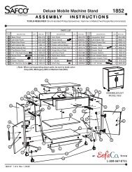
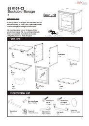
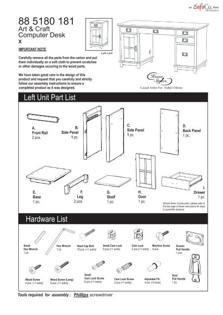
88 5180 181<br />
Art & Craft<br />
Computer Desk<br />
x<br />
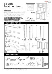
IMPORTANT NOTE<br />
Carefully remove all the parts from the carton and put<br />
them individually on a soft cloth to prevent scratches<br />
or other damages occuring to the wood parts.<br />
Left Unit<br />
We have taken great care in the design of this<br />
product and request that you carefully and strictly<br />
follow our assembly instructions to ensure a<br />
completed product as it was designed.<br />
Left Unit Part List<br />
Casual Attire For Today's Home<br />
A.<br />
Front Rail<br />
2 pcs.<br />
B.<br />
Side Panel<br />
1 pc.<br />
C.<br />
Side Panel<br />
1 pc.<br />
D.<br />
Back Panel<br />
1 pc.<br />
E.<br />
Base<br />
Hardware List<br />
F.<br />
G.<br />
H.<br />
Door<br />
I.<br />
Drawer<br />
1 pc.<br />
Leg<br />
Shelf<br />
1 pc. 2 pcs.<br />
1 pc.<br />
1 pc.<br />
(Knock-Down Construction, please refer to<br />
the last page of these instructions for steps<br />
to assemble drawers)<br />
Small<br />
Hex Wrench<br />
1 pc.<br />
Hex Wrench<br />
1 pc.<br />
Head Cap Bolt<br />
10 pcs. (+1 extra)<br />
Small Cam Lock<br />
6 pcs.(+1 extra)<br />
Cam Lock<br />
2 pcs.(+1 extra)<br />
Machine Screw<br />
4 pcs.<br />
Drawer<br />
Pull Handle<br />
1 pcs.<br />
Wood Screw<br />
4 pcs. (+1 extra)<br />
Wood Screw (Long)<br />
8 pcs. (+1 extra)<br />
Small<br />
Cam Lock Screw<br />
6 pcs.(+1 extra)<br />
Cam Lock Screw<br />
2 pcs.(+1 extra)<br />
Adjustable Pin<br />
4 pcs. (+2 extra)<br />
Door<br />
Pull Handle<br />
1 pc.<br />
Tools required for assembly : Phillips screwdriver
IMPORTANT<br />
Do not tighten up all the screws until each part is properly assembled.<br />
You should keep Hex Wrench in the safe place as you may need to tighten up the Head Cap Bolts in the future.<br />
Cam Lock Screw<br />
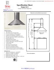
<strong>Assembly</strong> <strong>Instructions</strong> 2/4<br />
B<br />
C<br />
STEP 1<br />
Put Cam Lock Screws into the pre-drilled holes of Side Panel (B),(C) and tighten.<br />
A<br />
A<br />
B<br />
Cam Lock<br />
D<br />
C<br />
STEP 2<br />
Attach Front Rails (A) and Back Panel (D) to Side Panel (B) using Cam Locks.<br />
Attach Side Panel (C) to the unit using Cam Locks.
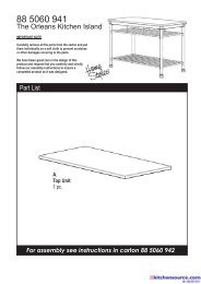
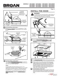
<strong>Assembly</strong> <strong>Instructions</strong> 3/4<br />
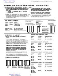
STEP 3<br />
Attach Base (E) to the unit with Head Cap Bolts.<br />
Attach Leg (F) to Base (E) with Head Cap Bolts.<br />
F<br />
E<br />
(Figure 1)<br />
F<br />
Head Cap Bolt<br />
STEP 4<br />
(Figure 2)<br />
Machine Screw<br />
Turn the unit to its upright position.<br />
I<br />
Slide Drawer (I) into place.<br />
Insert Adjustable Pins<br />
Into both side panels at<br />
the desired level.<br />
Pull Handle<br />
H<br />
G<br />
Slide Shelf (G) into place.<br />
Assemble Pull Handle<br />
to Door (H) with Machine Screws.<br />
(see Figure 1)<br />
Attach Door (H) to the side panels<br />
by sliding the door lift hinges into<br />
the side panel lift hinges.<br />
(see Figure 2)<br />
Adjustable Pin
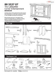
<strong>Assembly</strong> <strong>Instructions</strong> 4/4<br />
Drawer (I)<br />
I3<br />
I1<br />
STEP 1<br />
Attach I1 to I3 and I4, using<br />
a Phillips screwdriver and<br />
long wood screws (4X),<br />
tighten halfway.<br />
Figure 1<br />
I2<br />
I4<br />
Attach I2 to I3 and I4 using<br />
long wood screws (4X),<br />
tighten halfway. (see Figure 1)<br />
STEP 2<br />
MAKE SURE ROLLER<br />
IS ON THE BACK<br />
Slide I5 into the grooves in I3<br />
and I4. Be sure to push I5 all<br />
the way forward so it meets I1.<br />
(see Figure 2)<br />
I3<br />
I1<br />
Figure 2<br />
I3<br />
I5<br />
I1<br />
I5<br />
I2<br />
I4<br />
Figure 3<br />
I2<br />
STEP 3<br />
Part List<br />
I4<br />
Insert short wood screws (6X)<br />
into the pre-drilled holes in I5,<br />
tighten screws. (see Figure 3)<br />
Figure 4<br />
STEP 4<br />
Attach hardware pulls with<br />
machine screws.<br />
(see Figure 4)<br />
Tighten all screws used in<br />
drawer assembly.<br />
I1.<br />
Front Part<br />
1 pc.<br />
I2.<br />
Back Part<br />
1 pc.<br />
I3.<br />
Side Part<br />
1 pc.<br />
I4.<br />
Side Part<br />
1 pc.<br />
I5.<br />
Base Part<br />
1 pc.
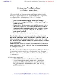
Tools required for assembly : Phillips screwdriver<br />
88 5180 182<br />
Art & Craft<br />
Computer Desk<br />
x<br />
IMPORTANT NOTE<br />
Carefully remove all the parts from the carton and put<br />
them individually on a soft cloth to prevent scratches<br />
or other damages occuring to the wood parts.<br />
Right Unit<br />
We have taken great care in the design of this<br />
product and request that you carefully and strictly<br />
follow our assembly instructions to ensure a<br />
completed product as it was designed.<br />
Right Unit Part List<br />
Casual Attire For Today's Home<br />
A.<br />
Front Rail<br />
1 pc.<br />
B.<br />
Front Rail<br />
2 pcs.<br />
E.<br />
Back Panel<br />
1 pc.<br />
C.<br />
Side Panel<br />
1 pc.<br />
D.<br />
Side Panel<br />
1 pc.<br />
F.<br />
Base<br />
1 pc.<br />
Hardware List<br />
I.<br />
Drawer<br />
1 pc.<br />
G.<br />
H.<br />
Leg<br />
Drawer<br />
2 pcs. 2 pcs.<br />
(Knock-Down Construction, please refer to<br />
the last page of these instructions for steps<br />
to assemble drawers)<br />
Small<br />
Hex Wrench<br />
1 pc.<br />
Hex Wrench<br />
1 pc.<br />
Head Cap Bolt<br />
10 pcs. (+1 extra)<br />
Small Cam Lock<br />
6 pcs.(+1 extra)<br />
Cam Lock<br />
2 pcs.(+1 extra)<br />
Machine Screw<br />
6 pcs.<br />
Wood Screw<br />
12 pcs. (+1 extra)<br />
Wood Screw (Long)<br />
28 pcs. (+1 extra)<br />
Small<br />
Cam Lock Screw<br />
6 pcs.(+1 extra)<br />
Cam Lock Screw<br />
2 pcs.(+1 extra)<br />
Drawer<br />
Pull Handle<br />
3 pcs.
IMPORTANT<br />
Do not tighten up all the screws until each part is properly assembled.<br />
You should keep Hex Wrench in the safe place as you may need to tighten up the Head Cap Bolts in the future.<br />
Cam Lock Screw<br />
<strong>Assembly</strong> <strong>Instructions</strong> 2/5<br />
C<br />
D<br />
STEP 1<br />
Put Cam Lock Screws into the pre-drilled holes of Side Panel (C), (D) and tighten.<br />
A<br />
B<br />
B<br />
C<br />
Cam Lock<br />
E<br />
D<br />
STEP 2<br />
Attach Front Rail (A), (B) Back Panel (E) to Side Panel (C) using Cam Locks.<br />
Attach Side Panel (D) to the unit using Cam Locks.
<strong>Assembly</strong> <strong>Instructions</strong> 3/5<br />
STEP 3<br />
Attach Base (F) to the unit with Head Cap Bolts.<br />
Attach Leg (G) to Base (F) with Head Cap Bolts.<br />
G<br />
F<br />
G<br />
Head Cap Bolt<br />
H<br />
H<br />
STEP 4<br />
Turn the unit to its upright position.<br />
Slide Drawer (H) and (I) into place.<br />
I
<strong>Assembly</strong> <strong>Instructions</strong> 4/5<br />
Drawer (H)<br />
H3<br />
H1<br />
STEP 1<br />
Attach H1 to H3 and H4, using<br />
a Phillips screwdriver and<br />
long wood screws (4X),<br />
tighten halfway.<br />
Figure 1<br />
H2<br />
H4<br />
Attach H2 to H3 and H4 using<br />
long wood screws (4X),<br />
tighten halfway. (see Figure 1)<br />
STEP 2<br />
MAKE SURE ROLLER<br />
IS ON THE BACK<br />
Slide H5 into the grooves in H3<br />
and H4. Be sure to push H5 all<br />
the way forward so it meets H1.<br />
(see Figure 2)<br />
H3<br />
H1<br />
Figure 2<br />
H3<br />
H5<br />
H1<br />
H5<br />
H2<br />
H4<br />
Figure 3<br />
H2<br />
STEP 3<br />
Part List<br />
H4<br />
Insert short wood screws (6X)<br />
into the pre-drilled holes in H5,<br />
tighten screws. (see Figure 3)<br />
Figure 4<br />
STEP 4<br />
Attach hardware pulls with<br />
machine screws.<br />
(see Figure 4)<br />
Tighten all screws used in<br />
drawer assembly.<br />
H1.<br />
Front Part<br />
2 pcs.<br />
H2.<br />
Back Part<br />
2 pcs.<br />
H3.<br />
Side Part<br />
2 pcs.<br />
H4.<br />
Side Part<br />
2 pcs.<br />
H5.<br />
Base Part<br />
2 pcs.
<strong>Assembly</strong> <strong>Instructions</strong> 5/5<br />
Drawer (I)<br />
STEP 1<br />
STEP 2<br />
I3<br />
I2<br />
Figure 1<br />
MAKE SURE ROLLER<br />
IS ON THE BACK<br />
Slide I5 into the grooves in I3<br />
and I4. Be sure to push I5 all<br />
the way forward so it meets I1.<br />
(see Figure 2)<br />
I1<br />
I3<br />
I5<br />
I1<br />
I4<br />
Figure 2<br />
I2<br />
Attach I1 to I3 and I4, using<br />
a Phillips screw driver and<br />
long wood screws (8X),<br />
tighten halfway.<br />
Attach I2 to I3 and I4 using<br />
long wood screws (8X),<br />
tighten halfway. (see Figure 1)<br />
I3<br />
I5<br />
I1<br />
I4<br />
I2<br />
I4<br />
I6<br />
STEP 4<br />
Attach hardware pulls with<br />
machine screws.<br />
STEP 3<br />
Part List<br />
Figure 3<br />
Insert short wood screws (4X)<br />
into the pre-drilled holes in I5,<br />
tighten screws. (see Figure 3)<br />
Figure 4<br />
Remove the tape holding<br />
the Metal Strips in place.<br />
You can adjust the Metal Strip<br />
for letter size or legal size<br />
file as shown. (see Figure 4)<br />
Tighten all screws used in<br />
drawer assembly.<br />
I1.<br />
Front Part<br />
1 pc.<br />
I2.<br />
Back Part<br />
1 pc.<br />
I3.<br />
Side Part<br />
1 pc.<br />
I4.<br />
Side Part<br />
1 pc.<br />
I5.<br />
Base Part<br />
1 pc.<br />
I6.<br />
Metal Strip<br />
2 pcs.
Tools required for assembly : Phillips screwdriver<br />
88 5180 183<br />
Art & Craft<br />
Computer Desk<br />
x<br />
IMPORTANT NOTE<br />
Carefully remove all the parts from the carton and put<br />
them individually on a soft cloth to prevent scratches<br />
or other damages occuring to the wood parts.<br />
Top Unit<br />
We have taken great care in the design of this<br />
product and request that you carefully and strictly<br />
follow our assembly instructions to ensure a<br />
completed product as it was designed.<br />
Top Unit Part List<br />
Casual Attire For Today's Home<br />
A.<br />
Top<br />
1 pc.<br />
B1.<br />
Front Part<br />
1 pc.<br />
B3.<br />
Side Part<br />
1 pc.<br />
B4.<br />
Side Part<br />
1 pc.<br />
B2.<br />
Base<br />
1 pc.<br />
B5.<br />
Back Part<br />
1 pc.<br />
B6.<br />
Rail<br />
2 pcs.<br />
Hardware List<br />
Small<br />
Hex Wrench<br />
1 pc.<br />
Hex Wrench<br />
1 pc.<br />
Head Cap Bolt<br />
24 pcs. (+1 extra)<br />
Machine Screw<br />
2 pcs.<br />
Pull Handle<br />
1 pcs.<br />
Wood Screw<br />
6 pcs. (+1 extra)
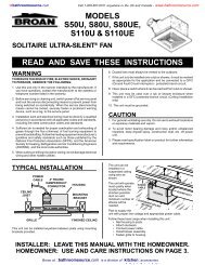
IMPORTANT<br />
Do not tighten up all the screws until each part is properly assembled.<br />
You should keep Hex Wrench in the safe place as you may need to tighten up the Head Cap Bolts in the future.<br />
STEP 1<br />
Attach Rail (B6) and Back Part (B5) to Side Part (B3)<br />
with Head Cap Bolts, then attach Side Part (B4) to<br />
the unit with Head Cap Bolts and tighten.<br />
(see Figure 1)<br />
Attach assembled drawer box in Step 1 to Left Unit<br />
and Right Unit with Head Cap Bolts.<br />
<strong>Assembly</strong> <strong>Instructions</strong> 2/2<br />
B3<br />
Figure 1<br />
B6<br />
B6<br />
B5<br />
B4<br />
Head Cap Bolt<br />
Head Cap Bolt<br />
Left Units<br />
Right Unit<br />
Machine Screw<br />
B1<br />
B2<br />
STEP 2<br />
Attach Pull Handle to Front Part (B1) with<br />
Machine Screws, then attach Front Part (B1)<br />
to Base (B2) with Wood Screws. (see Figure 2)<br />
Pull Handle<br />
Wood Screw<br />
Head Cap Bolt<br />
A<br />
STEP 3<br />
Place Top (A) on the unit with Head Cap Bolts.<br />
Slide drawer assembled in Step 2 into Place.