Construction Standards for Sand Lined Trench Systems
Construction Standards for Sand Lined Trench Systems
Construction Standards for Sand Lined Trench Systems

You also want an ePaper? Increase the reach of your titles
YUMPU automatically turns print PDFs into web optimized ePapers that Google loves.
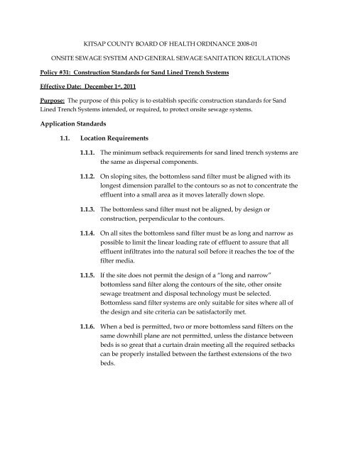
KITSAP COUNTY BOARD OF HEALTH ORDINANCE 2008-01<br />
ONSITE SEWAGE SYSTEM AND GENERAL SEWAGE SANITATION REGULATIONS<br />
Policy #31: <strong>Construction</strong> <strong>Standards</strong> <strong>for</strong> <strong>Sand</strong> <strong>Lined</strong> <strong>Trench</strong> <strong>Systems</strong><br />
Effective Date: December 1 st , 2011<br />
Purpose: The purpose of this policy is to establish specific construction standards <strong>for</strong> <strong>Sand</strong><br />
<strong>Lined</strong> <strong>Trench</strong> <strong>Systems</strong> intended, or required, to protect onsite sewage systems.<br />
Application <strong>Standards</strong><br />
1.1. Location Requirements<br />
1.1.1. The minimum setback requirements <strong>for</strong> sand lined trench systems are<br />
the same as dispersal components.<br />
1.1.2. On sloping sites, the bottomless sand filter must be aligned with its<br />
longest dimension parallel to the contours so as not to concentrate the<br />
effluent into a small area as it moves laterally down slope.<br />
1.1.3. The bottomless sand filter must not be aligned, by design or<br />
construction, perpendicular to the contours.<br />
1.1.4. On all sites the bottomless sand filter must be as long and narrow as<br />
possible to limit the linear loading rate of effluent to assure that all<br />
effluent infiltrates into the natural soil be<strong>for</strong>e it reaches the toe of the<br />
filter media.<br />
1.1.5. If the site does not permit the design of a “long and narrow”<br />
bottomless sand filter along the contours of the site, other onsite<br />
sewage treatment and disposal technology must be selected.<br />
Bottomless sand filter systems are only suitable <strong>for</strong> sites where all of<br />
the design and site criteria can be satisfactorily met.<br />
1.1.6. When a bed is permitted, two or more bottomless sand filters on the<br />
same downhill plane are not permitted, unless the distance between<br />
beds is so great that a curtain drain meeting all the required setbacks<br />
can be properly installed between the farthest extensions of the two<br />
beds.
1.2. Installation Issues<br />
Design <strong>Standards</strong><br />
1.2.1. Check the moisture content of the soil at 7-8 inches deep. If it is too<br />
wet, smearing and compaction will result, reducing the infiltration<br />
capacity of the soil.<br />
1.2.2. In order to prevent differential settling when the sand lined trench<br />
system is put into service, the filter media must have a uni<strong>for</strong>m<br />
density throughout.<br />
1.2.3. A geotextile filter fabric must be placed on the gravel bed. The cover<br />
soil must be capable of maintaining vegetative growth while not<br />
impeding the passage of air.<br />
1.2.4. Both the top surface of the filter media and the bottom of the<br />
excavation must be level within ±0.5 inch. However, the surface<br />
should be broken up with the backhoe teeth to minimize the <strong>for</strong>mation<br />
of a distinct layer between the sand and the original, undisturbed soil.<br />
1.3. Filter Bed<br />
1.3.1. Coarse <strong>Sand</strong> Media Specification<br />
The filter media must meet items a, b, and c, below:<br />
a. Particle size distribution<br />
Sieve Particle Size Percent Passing<br />
3/8 in 9.50 mm 100<br />
No. 4 4.75 mm 95 to 100<br />
No. 8 2.36 mm 80 to 100<br />
No. 16 1.18 mm 45 to 85<br />
No. 30 0.6 mm 15 to 60<br />
No. 50 0.3 mm 3 to 15<br />
No. 100 0.15 mm 0 to 4
. Effective Particle Size (D10) > 0.3 mm.<br />
c. Uni<strong>for</strong>mity Coefficient (D60/ D10) < 4.0<br />
1.3.2. Filter Bed Sizing<br />
2.1.2.1 Sizing the Infiltrative Surface – The minimum required<br />
infiltrative surface area must be determined by dividing the<br />
design flow estimate by the loading rate of the receiving soils.<br />
2.1.2.2 Depth of Media – The depth of filter media is dependent up the<br />
treatment level required of a given site. There must always be<br />
a minimum depth of 12 inches of filter media regardless of the<br />
level of pretreatment.<br />
2.1.2.2.1 In order to be expected to produce effluent meeting<br />
Treatment Level B, a minimum depth of 24 inches of<br />
filter media is required regardless of the level of<br />
pretreatment. This means that a sand lined trench<br />
system with a minimum of 24 inches of media<br />
preceded by a treatment technology identified on the<br />
List of Registered On-site Treatment and<br />
Distribution Products as meeting Treatment Level B<br />
can be expected to produce effluent meeting<br />
Treatment Level A.<br />
1.3.3. Excavation Depth – The infiltrative surface at the bottom of the filter<br />
media must be installed at least 6 inches in to original, undisturbed<br />
soil, except where the original soil is Soil Type 1. The maximum<br />
excavation depth <strong>for</strong> the filter media placement shall not exceed ten<br />
feet from finish grade.<br />
1.3.4. Absorption beds are allowed if the receiving soil is Soil Type 1, 2, 3 or<br />
fine sand. The maximum bed width must be no greater than 10 feet.<br />
1.3.5. Filter bed containment: The bottomless sand filter containment vessel<br />
must be designed and constructed to con<strong>for</strong>m to the containment<br />
standards set <strong>for</strong>th in Section 1.7 & 1.8.<br />
1.4. Wastewater Distribution<br />
1.4.1. Pressure distribution: Pressure distribution is required and must<br />
comply with the pressure distribution standards and guidance. This<br />
requirement applies to all pressure distribution related components.
1.4.2. A minimum of one orifice per 6 ft 2 of infiltrative surface area,<br />
evenly distributed, is required.<br />
1.4.3. Wastewater application to the filter bed: The wastewater must be<br />
applied to the layer of drain rock atop the filter media, or sprayed<br />
upward against the top of gravelless chambers.<br />
1.5. Air Coil<br />
An Air Coil may be called <strong>for</strong> as a requirement by the designer. When<br />
required it is to be installed between the native ground surface and the sand<br />
interface.<br />
1.6. Monitoring Ports<br />
2 monitoring ports are required. 1 installed to the native soil at the bottom of<br />
the dispersal trench and the other to be installed at the sand/gravel/chamber<br />
interface.<br />
1.7. Concrete Containment Vessel: to be designed and/or approved by a<br />
qualified professional engineer if the following conditions are not met.<br />
1.7.1. Above ground tank.<br />
Must be designed as follows, or as approved by the Health Officer:<br />
1. Walls<br />
a. at least 6 inches thick<br />
b. 4 feet or less in height<br />
c. rebar rein<strong>for</strong>cement: 3/8 inch diameter rebar on 2-foot<br />
centers horizontally and vertically, with continuous<br />
lengths wrapped around the corners.<br />
2. Tank sides are to be designed, constructed, and sealed to be<br />
water-tight.<br />
1.7.2. Below ground tank.<br />
The design of any such tank is to be approved by a qualified<br />
professional engineer and, where required by local and/or state<br />
regulation, the local health officer.
1. Septic designer must test and certify that the vessel sides are<br />
watertight.<br />
1.8. Constructed Wood Containment Vessel<br />
Must be designed as follows, or as approved by the Health Officer:<br />
1.8.1. Above ground wood vessel.<br />
A 30 mil PVC liner must be used. The design of any such tank is to be<br />
approved by a qualified professional engineer and, where required by<br />
local and/or state regulation, the local health officer.<br />
1.8.2. Below ground wood vessel.<br />
1. Walls<br />
a. ½” plywood<br />
b. 2 x 4 or 2 x 2 rim<br />
c. 30 mil liner<br />
2. Tank sides are to be designed, constructed, and sealed to be<br />
water-tight.
1.9. Figures<br />
1.9.1. Bottomless <strong>Sand</strong> Filter (example)