Hinges with built-in safety multiple switch
Hinges with built-in safety multiple switch
Hinges with built-in safety multiple switch

You also want an ePaper? Increase the reach of your titles
YUMPU automatically turns print PDFs into web optimized ePapers that Google loves.
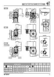
4<br />
<strong>H<strong>in</strong>ges</strong> <strong>with</strong> <strong>built</strong>-<strong>in</strong> <strong>safety</strong> <strong>multiple</strong> <strong>switch</strong><br />
Assembly <strong>in</strong>structions<br />
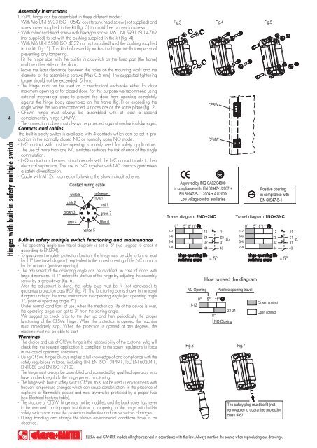
CFSW. h<strong>in</strong>ge can be assembled <strong>in</strong> three different modes:<br />
- With M6 UNI 5933 ISO 10642 countersunk-head screw (not supplied) and<br />
screw cover supplied <strong>in</strong> the kit (fig. 3) to avoid free access to screws.<br />
- With cyl<strong>in</strong>drical-head screw <strong>with</strong> hexagon socket M6 UNI 5931 ISO 4762<br />
(not supplied) to set <strong>with</strong> the bush<strong>in</strong>g supplied <strong>in</strong> the kit (fig. 4).<br />
- With M6 UNI 5588 ISO 4032 nut (not supplied) and the bush<strong>in</strong>g supplied<br />
<strong>in</strong> the kit (fig. 5). This k<strong>in</strong>d of assembly makes the h<strong>in</strong>ge totally tamper-proof<br />
prevent<strong>in</strong>g any tamper<strong>in</strong>g.<br />
- Fit the h<strong>in</strong>ge side <strong>with</strong> the <strong>built</strong>-<strong>in</strong> micro<strong>switch</strong> on the fixed part (the frame)<br />
and the other side on the door.<br />
- Leave the least clearance between the holes on the mount<strong>in</strong>g walls and the<br />
diameter of the assembl<strong>in</strong>g screws (Max 0.5 mm). The suggested tighten<strong>in</strong>g<br />
torque should not be exceeded: 5 Nm.<br />
- The h<strong>in</strong>ge must not be used as a mechanical end-stroke either for door<br />
maximum open<strong>in</strong>g or for closed door. For this purpose we recommend us<strong>in</strong>g<br />
external mechanical stops to prevent the door from open<strong>in</strong>g completely<br />
aga<strong>in</strong>st the h<strong>in</strong>ge body assembled on the frame (fig.1) or exceed<strong>in</strong>g the<br />
angle where the two <strong>in</strong>terconnected surfaces are on the same plane (fig. 2).<br />
- CFSW. h<strong>in</strong>ge must always be assembled <strong>with</strong> at least a second<br />
complementary h<strong>in</strong>ge CFMW.<br />
- The connection cables must always be protected aga<strong>in</strong>st mechanical damages.<br />
Contacts and cables<br />
The <strong>built</strong>-<strong>in</strong> <strong>safety</strong> <strong>switch</strong> is available <strong>with</strong> 4 contacts which can be set <strong>in</strong> production<br />
<strong>in</strong> the normally closed NC or normally open NO mode.<br />
- NC contact <strong>with</strong> positive open<strong>in</strong>g is ma<strong>in</strong>ly used for <strong>safety</strong> applications.<br />
The use of more than one NC <strong>switch</strong>es reduces the risk of error of the s<strong>in</strong>gle<br />
commutation.<br />
- NO contact can be used simultaneously <strong>with</strong> the NC contact thanks to their<br />
electrical separation. The use of NO together <strong>with</strong> NC contacts guarantees<br />
a <strong>safety</strong> diversification.<br />
- Cable <strong>with</strong> M12x1 connector follow<strong>in</strong>g the shown circuit scheme.<br />
Built-<strong>in</strong> <strong>safety</strong> <strong>multiple</strong> <strong>switch</strong> function<strong>in</strong>g and ma<strong>in</strong>tenance<br />
- The operat<strong>in</strong>g angle (see travel diagram) is set at 5° (we suggest to check it<br />
accord<strong>in</strong>g to EN294).<br />
- To guarantee the <strong>safety</strong> protection function, the h<strong>in</strong>ge must be able to turn at least<br />
by 11° (see travel diagram), equivalent to the forced open<strong>in</strong>g of the NC contacts<br />
by the actuator (positive open<strong>in</strong>g).<br />
- The adjustment of the operat<strong>in</strong>g angle can be modified, <strong>in</strong> case of doors <strong>with</strong><br />
large dimensions, till 1° before the start up of the h<strong>in</strong>ge by adjust<strong>in</strong>g the assembly<br />
screw by a screwdriver (fig. 6).<br />
After the adjustment is done, the <strong>safety</strong> plug must be fit (not removable) to<br />
guarantee protection class IP67 (fig. 7). The function<strong>in</strong>g po<strong>in</strong>ts shown <strong>in</strong> the travel<br />
diagram undergo the same variation as the operat<strong>in</strong>g angle (ex: operat<strong>in</strong>g angle<br />
1°, positive operat<strong>in</strong>g angle 7°).<br />
Under normal conditions of use, when the mechanical life of the device is over,<br />
the operat<strong>in</strong>g angle can get to 3° from the start<strong>in</strong>g angle.<br />
- We suggest to check prior to the start up and then periodically the proper<br />
function<strong>in</strong>g of the CFSW. h<strong>in</strong>ge. When the protection is opened the mach<strong>in</strong>e<br />
must immediately stop. When the protection is opened at any degrees, the<br />
mach<strong>in</strong>e must not be able to start.<br />
Warn<strong>in</strong>gs<br />
- The choice and use of CFSW. h<strong>in</strong>ge is the responsibility of the customer who will<br />
check that the relevant application is compliant to the <strong>safety</strong> regulations <strong>in</strong> force<br />
<strong>in</strong> the actual operat<strong>in</strong>g conditions.<br />
- Us<strong>in</strong>g CFSW. h<strong>in</strong>ges always implies a full knowledge of and compliance <strong>with</strong> the<br />
<strong>safety</strong> regulations <strong>in</strong> force, <strong>in</strong>clud<strong>in</strong>g UNI EN ISO 13849-1, IEC EN 60204-1,<br />
EN1088 and EN ISO 12100.<br />
- The h<strong>in</strong>ge must always be assembled and connected by qualified operators who<br />
have to check regularly the h<strong>in</strong>ge perfect function<strong>in</strong>g.<br />
- The h<strong>in</strong>ge <strong>with</strong> <strong>built</strong>-<strong>in</strong> <strong>safety</strong> <strong>switch</strong> CFSW. must not be used <strong>in</strong> environments <strong>with</strong><br />
frequent temperature changes which can cause condensation, <strong>in</strong> the presence of<br />
explosive or flammable gasses and must always be protected by a proper fuse<br />
(see Electrical features table).<br />
- The structure of CFSW. h<strong>in</strong>ge must not be modified and the back cover has never<br />
to be removed: an improper <strong>in</strong>stallation or tamper<strong>in</strong>g of the h<strong>in</strong>ge <strong>with</strong> <strong>built</strong>-<strong>in</strong><br />
<strong>safety</strong> <strong>switch</strong> can make the protection <strong>in</strong>effective and cause serious damages.<br />
- Dur<strong>in</strong>g handl<strong>in</strong>g and storage the shown environmental conditions have to be<br />
observed.<br />
ELESA and GANTER models all rights reserved <strong>in</strong> accordance <strong>with</strong> the law. Always mention the source when reproduc<strong>in</strong>g our draw<strong>in</strong>gs.