IPL, POULAN PRO, PB195H42LT, 2011-08, 532445181R1, NAen ...
IPL, POULAN PRO, PB195H42LT, 2011-08, 532445181R1, NAen ...
IPL, POULAN PRO, PB195H42LT, 2011-08, 532445181R1, NAen ...

You also want an ePaper? Increase the reach of your titles
YUMPU automatically turns print PDFs into web optimized ePapers that Google loves.
IMPORTANT MANUAL<br />
Do Not Throw Away<br />
REPAIR PART'S MANUAL<br />
MODEL:<br />
<strong>PB195H42LT</strong><br />
LAWN TRACTOR<br />
WARNING:<br />
Read this Man u al and follow all Warnings<br />
and Safety Instructions. Failure to do so<br />
can re sult in serious injury.<br />
ALWAYS WEAR EYE <strong>PRO</strong>TECTION DURING OPERATION<br />
Visit our website: www.poulanpro.com<br />
532 44 51-81 Rev 1<br />
10.05.11 BD<br />
Printed in the U.S.A.
HOW TO USE THIS MANUAL<br />
This manual is designed to provide the customer with a means to identify the parts on his/her tractor<br />
when ordering repair parts. The illustrations may or may not represent the actual assemblies; therefore,<br />
it is not recommended to use this manual as a guide to assemble or disassemble the tractor. Some<br />
hardware and parts are drawn larger in order to more readily identify them.<br />
Each tractor has its own model number.<br />
The model number for your tractor can be found on the fender under the seat.<br />
When ordering parts, always give the following information:<br />
• Product - “Tractor”<br />
• MODEL NUMBER - “<strong>PB195H42LT</strong> (96042013601)”<br />
• Part Number<br />
• Part Description<br />
TABLE OF CONTENTS<br />
SCHEMATIC ................................................................................................................ 3<br />
ELECTRICAL ............................................................................................................4-5<br />
CHASSIS ..................................................................................................................6-7<br />
DRIVE........................................................................................................................8-9<br />
ENGINE .................................................................................................................10-11<br />
STEERING ............................................................................................................12-13<br />
MOWER DECK .....................................................................................................14-15<br />
MOWER LIFT ............................................................................................................. 16<br />
SEAT ..........................................................................................................................17<br />
DECALS ..................................................................................................................... 18<br />
WARRANTY ............................................................................................................... 19<br />
PARTS AND SERVICE .............................................................................................. 20<br />
2
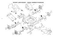
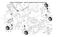
TRACTOR - - MODEL NUMBER <strong>PB195H42LT</strong> (96042013601), <strong>PRO</strong>DUCT NO. 960 42 01-36<br />
SCHEMATIC<br />
SCH11<br />
RED<br />
A<br />
AMMETER<br />
(OPTIONAL)<br />
FUSE<br />
BATTERY<br />
RED<br />
SOLENOID<br />
BLACK<br />
STARTER<br />
M<br />
WHITE<br />
WHITE<br />
B<br />
S<br />
M<br />
G<br />
L<br />
A1<br />
A2<br />
ATTACHMENT CLUTCH<br />
(CLUTCH OFF)<br />
BLACK<br />
CLUTCH/BRAKE<br />
(PEDAL UP)<br />
GRAY<br />
BLACK<br />
REVERSE SWITCH<br />
(NOT IN REVERSE)<br />
BLACK<br />
BLACK<br />
BLACK<br />
BLACK<br />
2<br />
3<br />
1<br />
BLACK<br />
BLACK<br />
BLACK<br />
SEAT SWITCH<br />
(NOT OCCUPIED)<br />
6<br />
GRAY<br />
NOTE<br />
YOUR TRACTOR IS<br />
EQUIPPED WITH A SPECIAL<br />
ALTERNATOR SYSTEM.<br />
THE LIGHTS ARE NOT<br />
CONNECTED TO THE<br />
BATTERY, BUT HAVE THEIR<br />
OWN ELECTRICAL SOURCE.<br />
BECAUSE OF THIS, THE<br />
BRIGHTNESS OF THE LIGHTS<br />
WILL CHANGE WITH ENGINE<br />
SPEED. AT IDLE THE LIGHTS<br />
WILL DIM. AS THE ENGINE IS<br />
SPEEDED UP, THE LIGHTS<br />
WILL BECOME THEIR<br />
BRIGHTEST.<br />
BLACK<br />
BLACK /WHITE<br />
BLUE<br />
BLUE<br />
FUEL<br />
LINE<br />
FUEL SHUT-OFF<br />
SOLENOID<br />
(IF SO EQUIPPED)<br />
RED<br />
LIGHT SWITCH<br />
IGNITION<br />
UNIT<br />
(OPTIONAL)<br />
HOUR<br />
METER<br />
ORANGE<br />
JUNCTION<br />
CONNECTOR<br />
CHASSIS<br />
HARNESS<br />
CHARGING SYSTEM OUTPUT<br />
3 AMP DC @ 3600 RPM<br />
SPARK<br />
PLUGS GAP<br />
(2 PLUGS ON<br />
TWIN CYL. ENGINES)<br />
BLACK<br />
12V<br />
POWER OUTLET<br />
(OPTIONAL)<br />
SHORTING<br />
CONNECTOR<br />
LIGHTING SYSTEM OUTPUT<br />
5 AMP AC @ 3600 RPM ALTERNATOR<br />
DIODE<br />
28 VOLTS AC MIN. @ 3600 RPM<br />
(CHARGING SYSTEM DISCONNECTED)<br />
14 VOLTS AC MIN. @ 3600 RPM (LIGHTS OFF)<br />
BROWN<br />
BLACK<br />
IGNITION SWITCH<br />
HEADLIGHTS<br />
POSITION CIRCUIT<br />
OFF<br />
RUN/OVERRIDE<br />
M+G+A1<br />
B+A1<br />
RUN B+A1<br />
START B+S+A1<br />
“MAKE”<br />
L+A2<br />
3<br />
2<br />
1<br />
CHASSIS HARNESS<br />
CONNECTOR<br />
(MATING SIDE)<br />
6<br />
5<br />
4<br />
6 3<br />
5 2<br />
4<br />
1<br />
DASH HARNESS<br />
CONNECTOR<br />
(MATING SIDE)<br />
WIRING INSULATED CLIPS<br />
NOTE: IF WIRING INSULATED<br />
CLIPS WERE REMOVED FOR<br />
SERVICING OF UNIT, THEY<br />
SHOULD BE RE-INSTALLED TO<br />
<strong>PRO</strong>PERLY SECURE YOUR<br />
WIRING.<br />
NON-REMOVABLE<br />
CONNECTIONS<br />
REMOVABLE<br />
CONNECTIONS<br />
3
TRACTOR - - MODEL NUMBER <strong>PB195H42LT</strong> (96042013601), <strong>PRO</strong>DUCT NO. 960 42 01-36<br />
ELECTRICAL<br />
T02S<br />
With 12V Outlet Option<br />
103<br />
79<br />
22<br />
21<br />
30<br />
33<br />
87<br />
59<br />
With Service Minder Option<br />
34<br />
43<br />
27<br />
42<br />
46<br />
26<br />
40<br />
41<br />
25<br />
16<br />
90<br />
71<br />
2<br />
29<br />
94<br />
28 55<br />
92<br />
93<br />
4
TRACTOR - - MODEL NUMBER <strong>PB195H42LT</strong> (96042013601), <strong>PRO</strong>DUCT NO. 960 42 01-36<br />
ELECTRICAL<br />
KEY PART<br />
NO. NO. DESCRIPTION<br />
1 532 16 34-65 Battery<br />
2 874 76 04-12 Bolt Hex Hd 1/4-20 unc x 3/4<br />
8 532 19 32-28 Box Battery<br />
16 532 17 61-38 Switch Interlock<br />
21 532 18 37-59 Harness Socket Light<br />
22 532 00 41-52 Bulb, Light #1156<br />
25 532 41 28-94 Cable Starter 6 Ga. BL/Red 14.5<br />
26 532 17 51-58 Fuse<br />
27 873 51 04-00 Nut Keps Hex 1/4-20 unc<br />
28 532 19 88-85 Cable Ground 18" Rear Battery Blk 6 Ga.<br />
29 532 40 15-45 Switch Seat<br />
30 532 19 33-50 Switch Ign<br />
33 532 41 19-33 Key/Chain<br />
34 532 11 07-12 Switch Light/Reset<br />
40 532 40 10-98 Harness Ign<br />
41 817 72 04-<strong>08</strong> Screw 1/4-20 unc x 1/2<br />
42 532 13 15-63 Cover Terminal Red<br />
43 532 19 25-07 Solenoid<br />
55 817 06 05-12 Screw 5/16-18 x 3/4<br />
71 532 44 15-44 Harness Ign. Chass.<br />
79 532 17 52-42 Socket Asm. Bulb<br />
87 532 19 78-02 Switch Interlock Clutch<br />
90 532 43 53-95 Cover Terminal<br />
92 532 19 66-15 Harness Pigtail Reverse Switch<br />
93 532 19 25-40 Screw Plastic 10-14 x 2.0<br />
94 532 19 18-34 Modual Reverse ROS<br />
NOTE: All component dimensions given in U.S. inches<br />
1 inch = 25.4 mm<br />
5
TRACTOR - - MODEL NUMBER <strong>PB195H42LT</strong> (96042013601), <strong>PRO</strong>DUCT NO. 960 42 01-36<br />
CHASSIS<br />
302<br />
153<br />
18<br />
14<br />
151<br />
137<br />
176<br />
5<br />
68<br />
236<br />
235<br />
68<br />
235<br />
150<br />
34<br />
130<br />
36<br />
176<br />
182<br />
176<br />
177<br />
175<br />
183<br />
68<br />
183<br />
236<br />
68<br />
213<br />
218<br />
181<br />
196<br />
37<br />
194<br />
176<br />
194<br />
180<br />
68<br />
138<br />
68<br />
228<br />
287<br />
162<br />
181<br />
159<br />
194<br />
189<br />
52<br />
217<br />
228<br />
Chassis-tex_elite basic_11<br />
159<br />
152<br />
189<br />
6
TRACTOR - - MODEL NUMBER <strong>PB195H42LT</strong> (96042013601), <strong>PRO</strong>DUCT NO. 960 42 01-36<br />
CHASSIS<br />
KEY PART<br />
NO. NO. DESCRIPTION<br />
5 532 41 17-64 Dash<br />
14 532 18 58-47 Hood<br />
18 532 42 67-92 Grille<br />
34 532 19 61-25 Plate Engine<br />
36 817 06 05-12 Screw 5/16-18 x 3/4<br />
37 532 43 65-23 Fender<br />
52 873 68 05-00 Nut Lock 5/16-18<br />
68 817 49 05-<strong>08</strong> Screw Thdrol 5/16-18 x 1/2<br />
130 532 41 63-58 Screw #10 x 0.750<br />
137 532 18 49-21 Bumper Hood<br />
138 532 40 97-30 Cupholder<br />
150 532 18 44-61 Duct Heat Hood<br />
151 532 40 78-07 Bracket Pivot<br />
152 532 19 95-35 Shield Browning<br />
153 532 18 98-37 Lens Grille<br />
159 817 00 06-12 Screw Hexwsh Thdrol 3/8-16 x 3/4<br />
162 532 14 24-32 Screw Hex Wsh Hi-Lo 1/4 x 1/2<br />
175 532 19 32-43 Crossmember<br />
176 532 40 07-76 Screw 10-24 x 5/8 Wshd Qdrx<br />
177 532 19 52-28 Bushing Steering<br />
180 532 19 54-57 Chassis<br />
181 532 40 47-96 Bushing Mtg. Fender Crgo.<br />
182 532 19 30-57 Dash Lower<br />
183 874 52 05-20 Bolt 5/16-18 x 1-1/4<br />
189 817 00 05-12 Screw 5/16-18 x 3/4<br />
194 873 90 05-00 Nut Lock Hex Flange 5/16-18<br />
196 532 41 45-79 Console Asm. Deck Lift<br />
213 874 76 05-12 Bolt 5/16-18 x 3/4<br />
217 532 40 91-67 Rod Pivot Hood<br />
218 532 19 63-95 X-Piece Hood Step<br />
228 532 19 51-61 Stud Fastener<br />
235 532 40 61-29 Spacer Fender<br />
236 873 93 05-00 Nut Center Lock 5/16-18<br />
287 817 60 04-06 Screw 1/4-20 x 3/8<br />
302 532 18 38-23 Insert Lens Reflective<br />
NOTE: All component dimensions given in U.S. inches<br />
1 inch = 25.4 mm<br />
7
TRACTOR - - MODEL NUMBER <strong>PB195H42LT</strong> (96042013601), <strong>PRO</strong>DUCT NO. 960 42 01-36<br />
DRIVE<br />
70<br />
56<br />
74<br />
143<br />
216<br />
171<br />
221<br />
184<br />
35<br />
125<br />
42<br />
227<br />
80 125<br />
125<br />
64<br />
159<br />
167<br />
160<br />
170<br />
52<br />
226<br />
29<br />
51<br />
159 15<br />
17<br />
190<br />
49<br />
188<br />
185<br />
186<br />
189<br />
187<br />
50<br />
51<br />
161<br />
211<br />
166<br />
279<br />
175<br />
178<br />
23<br />
153<br />
176<br />
174<br />
233<br />
232<br />
51<br />
33<br />
52<br />
183<br />
2<br />
116<br />
125<br />
225<br />
22<br />
166<br />
205<br />
230<br />
116<br />
99<br />
73<br />
1<br />
2<br />
230<br />
205<br />
33<br />
drive-tex_K46_fender_24_r1<br />
73<br />
8<br />
183
TRACTOR - - MODEL NUMBER <strong>PB195H42LT</strong> (96042013601), <strong>PRO</strong>DUCT NO. 960 42 01-36<br />
DRIVE<br />
KEY PART<br />
NO. NO. DESCRIPTION<br />
1 – – – – – – Transaxle, Tufftorq K46BA(4<strong>08</strong>214)<br />
(Order parts from transaxle<br />
manufacturer)<br />
2 532 12 35-83 Key Square<br />
15 819 13 13-16 Washer 13/32 x 13/16 x 16 Ga.<br />
17 532 41 36-78 Spring, Brake<br />
22 532 19 76-60 Rod Shift<br />
23 532 14 <strong>08</strong>-45 Knob<br />
29 532 40 38-06 Rod, Brake<br />
33 812 00 00-01 Ring E<br />
35 532 19 77-22 Rod, Brake, Park<br />
42 532 12 48-72 Cover, Foot Pedal<br />
49 872 11 06-14 Bolt<br />
50 532 19 43-27 Pulley Idler Flat<br />
51 873 90 06-00 Lock Nut 3/8-16<br />
52 532 19 43-26 Idler V-Groove 910" Offset<br />
56 532 13 09-69 V-Belt, Drive<br />
64 532 19 62-00 Shaft Asm. Pedal Brake Control<br />
70 532 41 13-29 Console<br />
73 874 49 05-40 Bolt Hex 5/16-18 x 2-1/2 G5<br />
74 532 14 24-32 Screw 1/4 x 1/2<br />
80 532 44 06-19 Strap Torque<br />
99 532 41 57-42 Rod Spring Bypass<br />
116 873 90 05-00 Nut Lock Hex Flange 5/16-18<br />
125 817 00 05-12 Screw 5/16-18 x 3/4<br />
143 817 49 05-<strong>08</strong> Screw THDROL 5/16-18<br />
153 532 12 47-88 Retainer Spring 1"<br />
159 876 02 04-12 Pin Cotter 1/8 x 3/4<br />
160 532 16 94-84 Retainer Clip<br />
161 532 10 57-09 Spring, Return, Clutch<br />
166 532 42 91-64 Nut Push .625<br />
KEY PART<br />
NO. NO. DESCRIPTION<br />
167 532 40 52-57 Latch Brake Parking<br />
170 532 19 43-22 Keeper Belt Centerspan<br />
171 872 11 06-16 Bolt 3/8-16 unc x 2<br />
174 532 19 72-89 Nut Push<br />
175 532 40 62-<strong>08</strong> Shaft Asm Shift<br />
176 532 19 62-14 Arm Clevis Rod Shift<br />
178 532 19 74-56 Spring Shift<br />
183 532 13 70-57 Spacer Axle<br />
184 532 44 15-04 Handle Parking Brake<br />
185 872 11 06-22 Bolt<br />
186 532 19 43-21 Spacer Retainer<br />
187 819 13 32-10 Washer<br />
188 532 19 43-23 Link Clutch Ground Drive<br />
189 532 19 43-17 Bellcrank Ground Drive<br />
190 532 19 43-18 Keeper Bellcrank Ground Drive<br />
205 532 12 17-48 Washer 25/32 x 1-5/8 x 16 Ga.<br />
211 532 19 62-12 Bushing Shaft<br />
216 532 19 61-31 Bracket Pulley Idler<br />
221 532 40 31-87 Retainer Spring Clip Handle<br />
225 532 40 33-19 Keeper Belt Transaxle<br />
226 532 40 15-64 Bracket Mount Torque<br />
227 817 49 05-12 Screw 5/16-18 x 3/4<br />
230 532 18 89-67 Washer Harden .793 x 1.637 x 060<br />
232 874 78 07-16 Bolt 7/16-14 x 1 Gr 5<br />
233 532 40 52-96 Washer Serrated<br />
279 532 40 62-07 Link Shift<br />
NOTE: All component dimensions given in U.S. inches<br />
1 inch = 25.4 mm<br />
9
TRACTOR - - MODEL NUMBER <strong>PB195H42LT</strong> (96042013601), <strong>PRO</strong>DUCT NO. 960 42 01-36<br />
ENGINE<br />
1<br />
21<br />
20<br />
45<br />
15<br />
18<br />
97<br />
96<br />
84<br />
122<br />
79<br />
37<br />
12<br />
69<br />
2<br />
28<br />
37<br />
42<br />
90<br />
85<br />
9<br />
114<br />
28<br />
29<br />
OPTIONAL EQUIPMENT<br />
Spark Arrester<br />
109<br />
111<br />
engine-tex_BS_45<br />
10
TRACTOR - - MODEL NUMBER <strong>PB195H42LT</strong> (96042013601), <strong>PRO</strong>DUCT NO. 960 42 01-36<br />
ENGINE<br />
KEY PART<br />
NO. NO. DESCRIPTION<br />
1 – – – – – – Engine B&S Model No. 31P677-<br />
4373-G1(440009)(Order parts from<br />
engine manufacturer)<br />
2 532 13 73-52 Muffler<br />
9 532 19 43-20 Keeper Belt Engine<br />
12 532 40 54-71 Pulley Engine<br />
15 532 42 07-21 Tank Fuel 1.50<br />
18 532 43 02-19 Cap Fuel<br />
20 532 17 05-45 Control Throttle/Choke<br />
21 532 41 63-58 Screw #10 x 0.750<br />
28 532 40 11-37 Fuel Line<br />
29 532 13 71-80 Spark Arrester Kit<br />
37 532 12 34-87 Clamp Hose<br />
42 810 04 07-00 Washer Lock 7/16<br />
45 873 51 04-00 Nut Keps Hex 1/4-20 unc<br />
69 532 16 52-91 Gasket<br />
79 532 19 23-34 Screw Socket Hd 5/16-18 x .75<br />
84 817 06 06-20 Screw 3/8-16 x 1-1/4<br />
85 532 17 39-37 Bolt Hex 7/16-20 x 4 x Gr. 5-1.5<br />
90 817 00 06-16 Screw 3/8-16 x 1.0<br />
96 819 09 14-16 Washer 9/32 x 7/8 x 16 Ga.<br />
97 817 67 04-12 Screw 1/4-20 x 3/4<br />
109 532 41 41-14 CanisterCarbon Filter Asm.<br />
111 532 41 41-19 Purge Line Carb.<br />
114 532 41 41-16 Cradle Canister Carbon<br />
122 532 42 19-22 Extension Drain Oil<br />
NOTE: All component dimensions given in U.S. inches<br />
1 inch = 25.4 mm<br />
For engine service and replacement parts, call the toll free<br />
number for your engine manufacturer listed below:<br />
Briggs & Stratton 1-800-233-3723<br />
Engine Power Rating Information<br />
The gross power rating for individual gas engine models is labeled in accordance with SAE (Society of Automotive Engineers)<br />
code J1940 (Small Engine Power & Torque Rating Procedure), and rating performance has been obtained and<br />
corrected in accordance with SAE J1995 (Revision 2002-05). Torque values are derived at 3060 RPM; horsepower values<br />
are derived at 3600 RPM. Actual gross engine power will be lower and is affected by, among other things, ambient operating<br />
conditions and engine-to-engine variability. Given both the wide array of products on which engines are placed and<br />
the variety of environmental issues applicable to operating the equipment, the gas engine will not develop the rated gross<br />
power when used in a given piece of power equipment (actual “on-site” or net power). This difference is due to a variety<br />
of factors including, but not limited to, accessories (air cleaner, exhaust, charging, cooling, carburetor, fuel pump, etc.),<br />
application limitations, ambient operating conditions (temperature, humidity, altitude), and engine-to-engine variability.<br />
Due to manufacturing and capacity limitations, Briggs & Stratton may substitute an engine of higher rated power for this<br />
Series engine.<br />
11
TRACTOR - - MODEL NUMBER <strong>PB195H42LT</strong> (96042013601), <strong>PRO</strong>DUCT NO. 960 42 01-36<br />
STEERING<br />
26<br />
72<br />
33<br />
45<br />
1<br />
20<br />
21<br />
71<br />
16<br />
13<br />
28<br />
64<br />
63<br />
22<br />
28<br />
60<br />
57<br />
9<br />
19<br />
59<br />
57<br />
63<br />
8<br />
7<br />
2<br />
67<br />
66<br />
9<br />
8 7<br />
35<br />
6<br />
58<br />
67<br />
61<br />
4<br />
69<br />
14<br />
15<br />
62<br />
14<br />
6<br />
5<br />
13<br />
8<br />
68<br />
70<br />
15<br />
13<br />
steering-tex_STDHRR_5_r1<br />
53<br />
12
TRACTOR - - MODEL NUMBER <strong>PB195H42LT</strong> (96042013601), <strong>PRO</strong>DUCT NO. 960 42 01-36<br />
STEERING<br />
KEY PART<br />
NO. NO. DESCRIPTION<br />
1 532 42 45-51 Wheel, Steering<br />
2 532 19 59-68 Axle Asm., Front<br />
4 532 40 30-87 Spindle Asm., LH<br />
5 532 40 30-88 Spindle Asm., RH<br />
6 532 12 49-31 Washer Thrust 0.75 x 1.23<br />
7 532 12 17-48 Washer 25/32 x 1-5/8 x 16 Ga.<br />
8 812 00 00-29 Ring, Clip #T5304-75<br />
9 532 12 12-32 Cap, Spindle<br />
13 532 12 17-49 Washer 25/32 x 1-1/4 x 16 Ga.<br />
14 810 04 06-00 Washer Lock 3/8<br />
15 873 54 06-00 Nut, Crown Lock 3/8-24 unf<br />
16 532 42 93-74 Shaft Steering<br />
19 532 19 47-29 Plate Steering<br />
20 532 41 12-91 Boot, Steering<br />
21 532 18 67-37 Adapter, Wheel Steering<br />
22 532 42 05-37 Strg. Supt. Lower<br />
26 532 42 45-53 Insert, Wheel Steering<br />
28 817 00 06-12 Screw 3/8-16 x 3/4<br />
33 810 04 05-00 Washer Lock 5/16<br />
35 532 19 47-32 Gear, Sector Plate<br />
45 819 11 38-12 Washer 11/32 x 2-3/8 x 12 Ga.<br />
53 532 18 89-67 Washer Hardened .793 x 1.637 x .060<br />
57 532 40 74-65 Bracket Upstop<br />
58 532 19 47-47 Bolt Shoulder Sector Pivot CFM<br />
59 532 19 47-48 Washer Thrust Sector Steering<br />
60 873 97 10-00 Nut Flange Lock 5/8-11<br />
61 532 19 47-40 Draglink, LH<br />
62 532 19 47-41 Draglink, RH<br />
63 817 00 05-12 Screw 5/16-18 x 3/4<br />
64 532 19 98-49 Retainer Clip Spring Steering<br />
66 871 02 07-48 Bolt Hex Fghd 7/16-14 x 3 Serr<br />
67 532 19 47-37 Bushing PM Front Axle<br />
68 873 90 07-00 Nut Lock Flange 7/16-14 Gr. 5<br />
69 532 19 91-62 Washer 1.5 x .505 x .118<br />
70 532 19 61-97 Bracket Deck Susp. Front<br />
71 532 19 07-52 Shaft Ext. Steering<br />
72 532 42 89-82 Bolt 5/16-18 x 4 W/Patch<br />
NOTE: All component dimensions given in U.S. inches<br />
1 inch = 25.4 mm<br />
13
TRACTOR - - MODEL NUMBER <strong>PB195H42LT</strong> (96042013601), <strong>PRO</strong>DUCT NO. 960 42 01-36<br />
SEAT<br />
1<br />
8<br />
41<br />
7<br />
8<br />
8<br />
7<br />
40<br />
8<br />
10<br />
21<br />
6<br />
37<br />
44<br />
43<br />
2<br />
37<br />
21<br />
3<br />
seat-tex_6.5SL_2<br />
KEY PART<br />
NO. NO. DESCRIPTION<br />
1 532 19 75-14 Seat<br />
2 532 18 01-66 Bracket Pivot Fender<br />
3 532 14 06-75 Strap, Asm Fender<br />
6 873 80 06-00 Nut, Lock w/Ins. 3/8-16 unc<br />
7 532 12 41-81 Spring, Seat Cprsn<br />
8 532 17 18-77 Bolt 5/16-18 unc x 3/4 w/Sems<br />
10 532 19 69-77 Pan, Seat<br />
21 532 17 18-52 Bolt, Shoulder 5/16-18<br />
KEY PART<br />
NO. NO. DESCRIPTION<br />
37 873 80 05-00 Nut, Lock 5/16-18 unc<br />
40 532 19 76-61 Handle Slide<br />
41 532 19 82-00 Spring Latch<br />
43 874 76 06-12 Bolt 3/8-16 unc x 3/4<br />
44 819 13 38-12 Washer 13/32 x 2 3/8 x 12 Ga.<br />
NOTE: All component dimensions given in U.S. inches<br />
1 inch = 25.4 mm<br />
14
TRACTOR - - MODEL NUMBER <strong>PB195H42LT</strong> (96042013601), <strong>PRO</strong>DUCT NO. 960 42 01-36<br />
11<br />
7<br />
3<br />
4 4<br />
3<br />
20<br />
9<br />
8<br />
12 5<br />
12<br />
2<br />
6<br />
1<br />
14<br />
KEY PART<br />
NO. NO. DESCRIPTION<br />
1 532 42 41-02 Decal, Warn Spark Arrestor<br />
2 532 42 95-55 Decal Eng. H.P.<br />
3 532 43 84-99 Decal Hood<br />
4 532 43 85-03 Decal Side Panel Logo<br />
5 532 17 05-63 Decal, Mower Warn.<br />
6 532 43 64-01 Decal, Emission<br />
7 532 43 84-27 Decal Replacement Parts<br />
8 532 41 16-57 Decal Fender Warn S/F<br />
9 532 43 85-02 Decal Fender Logo<br />
KEY PART<br />
NO. NO. DESCRIPTION<br />
11 532 43 85-01 Decal Ins Strg Whl<br />
12 532 43 84-92 Decal Fend SD<br />
14 532 16 03-96 Decal V-Belt Schematic<br />
20 532 14 50-05 Decal Bat Dan/Psn<br />
- - 532 16 69-60 Decal Bypass<br />
- - 532 40 95-05 Pad Footrest LH<br />
- - 532 41 12-73 Pad Footrest RH<br />
- - 532 44 03-04 Manual Operator's (E/S)<br />
- - 532 44 51-81 Manual Parts (E/S)<br />
WHEELS AND TIRES<br />
1<br />
2<br />
11 3<br />
7<br />
6<br />
4<br />
10<br />
5<br />
9<br />
8<br />
KEY PART<br />
NO. NO. DESCRIPTION<br />
1 532 05 91-92 Cap Valve Tire<br />
2 532 06 51-39 Stem Valve<br />
3 532 43 96-73 Rim Asm 6" Front<br />
4 532 05 99-04 Tube Front (Service Item Only)<br />
5 532 10 62-22 Tire F T 15 x 6 0 - 6<br />
6 532 12 49-57 Fitting Grease<br />
7 532 12 49-59 Bearing Flange (Front Wheel Only)<br />
8 532 17 50-39 Cap Axle<br />
9 532 13 84-68 Tire R T 20 x 8-8C<br />
10 532 12 49-26 Tube Rear (Service Item Only)<br />
11 532 44 <strong>08</strong>-81 Rim Asm 8" Rear Service<br />
- - 532 14 43-34 Sealant, Tire (Not Shown)<br />
NOTE: All component dimensions given in U.S. inches<br />
1 inch = 25.4 mm<br />
wheel_art_1-tex<br />
15
TRACTOR - - MODEL NUMBER <strong>PB195H42LT</strong> (96042013601), <strong>PRO</strong>DUCT NO. 960 42 01-36<br />
MOWER DECK<br />
70<br />
67<br />
152<br />
7<br />
37<br />
38<br />
30<br />
7<br />
43<br />
42<br />
56<br />
113<br />
40<br />
57 145<br />
59<br />
60<br />
57<br />
56<br />
64<br />
40<br />
36<br />
55<br />
46<br />
63<br />
147<br />
30<br />
38<br />
68<br />
195<br />
122<br />
123<br />
195<br />
117<br />
1<br />
116<br />
119<br />
118<br />
47<br />
192<br />
144<br />
241<br />
242<br />
34<br />
33<br />
32<br />
31<br />
30<br />
21<br />
118<br />
119<br />
117<br />
116<br />
62<br />
19<br />
6<br />
188<br />
189<br />
113<br />
6<br />
189<br />
188<br />
15<br />
69<br />
21<br />
29<br />
21<br />
23<br />
24<br />
25<br />
26<br />
19<br />
14<br />
20<br />
13<br />
69 69<br />
27<br />
11<br />
42_D_man-tex_LT_35<br />
8<br />
16
TRACTOR - - MODEL NUMBER <strong>PB195H42LT</strong> (96042013601), <strong>PRO</strong>DUCT NO. 960 42 01-36<br />
MOWER DECK<br />
KEY PART<br />
NO. NO. DESCRIPTION<br />
1 532 19 64-95 Mower Housing<br />
6 532 19 51-86 Arm Suspension<br />
7 532 41 63-58 Screw #10 x 0.750 BOS Thread<br />
8 532 19 30-03 Bolt/Washer Asm 7/16-20 unf<br />
11 532 13 89-71 Blade, 42" Hi-Lift<br />
15 532 11 04-85 Bearing, Ball, Mandrel<br />
19 532 19 65-39 Bolt, Shoulder<br />
20 532 15 97-70 Baffle, Vortex<br />
21 873 68 05-00 Nut, Crownlock 5/16-18 unc<br />
23 532 19 25-57 Bracket, Deflector<br />
24 532 10 53-04 Cap, Sleeve<br />
25 532 19 70-26 Spring, Torsion, Deflector<br />
26 532 11 04-52 Nut, Push<br />
27 532 40 30-04 Shield, Deflector<br />
29 532 13 14-91 Rod, Hinge<br />
30 532 17 39-84 Screw Thdrol Rolling Wsh Hd<br />
31 532 18 76-90 Washer, Spacer<br />
32 532 19 74-73 Pulley, Mandrel<br />
33 532 40 02-34 Nut, Toplock, Flanged<br />
34 872 11 06-12 Bolt Carr Sh. 3/8-16 x 1-1/2 Gr. 5<br />
36 532 19 73-79 Pulley, Idler 4.50 RAW<br />
37 819 13 13-16 Washer 13/32 x 13/16 x 16 Ga.<br />
38 532 43 25-20 Keeper Belt Mandrel<br />
40 873 90 06-00 Nut, Lock Flg. 3/8-16 unc<br />
42 532 19 84-10 Spring Torsion Brake<br />
43 532 19 72-56 Spring Torsion Retainer<br />
46 532 13 77-29 Screw Thd Roll 1/4-20 x 5/8<br />
47 532 19 72-50 Bracket Clutch Cable<br />
55 532 43 71-10 Arm, Idler<br />
56 532 19 90-92 Spacer, Retainer<br />
57 817 00 06-16 Screw Hexwsh Thd 3/8-16 x 1<br />
59 532 14 10-43 Guard, Tuv Idler (94)<br />
60 532 19 72-61 Arm Brake Mower<br />
KEY PART<br />
NO. NO. DESCRIPTION<br />
62 872 11 06-16 Bolt Rdhd Sqnk 3/8-16 unc x 2<br />
63 532 19 94-77 Arm Brake Mower<br />
64 532 19 97-90 Linkage Brake<br />
67 532 40 30-12 Handle, Clutch Cable<br />
68 532 42 96-36 V-Belt<br />
69 872 14 05-05 Bolt Rdhd Sqnk 5/16-18 x 5/8<br />
70 532 19 83-32 Clutch Asm. Manual<br />
113 817 00 05-10 Screw 5/16-18<br />
116 532 12 48-42 Bolt Shoulder<br />
117 532 18 86-06 Wheel Gage<br />
118 873 90 06-00 Nut Centerlock 3/8-16 unc<br />
119 819 12 14-14 Washer 3/8 x 7/8 x 14 Ga.<br />
122 532 19 72-58 Keeper Belt Eng. LH<br />
123 532 19 72-59 Keeper Belt Eng. RH<br />
144 532 19 92-04 Keeper Belt<br />
145 532 19 31-97 Pulley Idler Primary<br />
147 532 40 19-71 Spring Return<br />
152 532 43 51-11 Cable Clutch Manual w/Spr.<br />
188 532 19 51-61 Stud Fastener<br />
189 873 90 05-00 Nut Lock Hex Flange<br />
192 532 19 72-60 Bracket Brake Stand LH<br />
195 817 00 06-12 Screw Hexwsh Thdr 3/8-16 x 3/4<br />
241 532 15 29-27 Screw #10-32.5. 3/8 Flange<br />
242 532 41 55-98 Port Washout<br />
- - 532 19 28-70 Mandrel Assembly (Includes housing,<br />
shaft assembly, and bearing<br />
only - pulley/nut/washer and blade<br />
bolt/washers not included)<br />
- - 532 43 77-30 Replacement Mower, Complete<br />
NOTE: All component dimensions given in U.S. inches<br />
1 inch = 25.4 mm<br />
17
TRACTOR - - MODEL NUMBER <strong>PB195H42LT</strong> (96042013601), <strong>PRO</strong>DUCT NO. 960 42 01-36<br />
MOWER LIFT<br />
7<br />
87<br />
90 98<br />
10<br />
89<br />
3<br />
97<br />
100<br />
2<br />
91<br />
88<br />
97<br />
87<br />
89<br />
101*<br />
89<br />
87<br />
lift-tex_17_r3 *Key 91 may be substituted for Key 101<br />
KEY PART<br />
NO. NO. DESCRIPTION<br />
2 532 42 20-27 Shaft Asm., Cross Lift<br />
3 532 19 52-31 Lever Asm., Lift RH<br />
7 532 41 15-55 Grip, Lever<br />
10 532 19 63-14 Spring Torsion<br />
87 532 19 42-09 Pin Cotter 7/16 Bow Tie Lock<br />
88 532 41 07-10 Spring Lift Assist<br />
89 819 19 19-12 Washer Clear Zinc<br />
90 532 19 42-<strong>08</strong> Pin Cotter 5/16 Bow Tie Lock<br />
KEY PART<br />
NO. NO. DESCRIPTION<br />
91 532 19 51-81 Link Lift Susp Mower Rear<br />
97 817 00 06-12 Screw 3/8-16 x .75 Smgml Tap/R.Z<br />
98 532 19 52-70 Link Lift Susp. Front Mower<br />
100 873 93 06-00 Nut Centerlock 3/8 -16 unc<br />
101 532 40 70-03 Link Asm. Lift Fixed<br />
NOTE: All component dimensions given in U.S. inches<br />
1 inch = 25.4 mm<br />
18
LIMITED WARRANTY<br />
The Manufacturer warrants to the original consumer purchaser that this product as manufactured is free from defects in materials<br />
and work man ship. For a period of two (2) years from date of purchase by the original consumer purchaser, we will repair or<br />
replace, at our option, without charge for parts or labor incurred in replacing parts, any part which we find to be defective due<br />
to materials or workmanship. This Warranty is subject to the following limitations and exclusions.<br />
1. This warranty does not apply to the engine, transaxle/transmission components, battery (except as noted below) or components<br />
parts thereof. Please refer to the applicable manufacturer's warranty on these items.<br />
2. Transportation charges for the movement of any power equipment unit or attachment are the responsibility of the pur chaser.<br />
Transportation charges for any parts submitted for replacement under this warranty must be paid by the purchaser unless<br />
such return is requested by the manufacturer.<br />
3. Battery Warranty: On products equipped with a Battery, we will replace, without charge to you, any battery which we find<br />
to be defective in manufacture, during the first ninety (90) days of ownership. After ninety (90) days, we will exchange the<br />
Battery, charging you 1/12 of the price of a new Battery for each full month from the date of the original sale. Battery must<br />
be maintained in accordance with the instructions furnished.<br />
4. The Warranty period for any products used for rental or commercial purposes is limited to 90 days from the date of original<br />
purchase.<br />
5. This Warranty applies only to products which have been properly assembled, adjusted, operated, and main tained in accor<br />
dance with the instructions furnished. This Warranty does not apply to any product which has been subjected to alteration,<br />
misuse, abuse, improper assembly or installation, delivery damage, or to normal wear of the product.<br />
6. Exclusions: Excluded from this Warranty are belts, blades, blade adapters, normal wear, normal adjustments, stan dard<br />
hardware and normal maintenance.<br />
7. In the event you have a claim under this Warranty, you must return the product to an authorized service dealer.<br />
Should you have any unanswered questions concerning this Warranty, please contact:<br />
HOP<br />
Outdoor Products Customer Service Dept.<br />
9335 Harris Corners Parkway<br />
Charlotte, NC 28269 USA<br />
In Canada contact:<br />
HOP<br />
5855 Terry Fox Way<br />
Mississauga, Ontario<br />
L5V 3E4<br />
giving the model number, serial number and date of purchase of your product and the name and address of the authorized<br />
dealer from whom it was purchased.<br />
THIS WARRANTY DOES NOT APPLY TO INCIDENTAL OR CONSEQUENTIAL DAMAGES AND ANY IMPLIED WAR RAN-<br />
TIES ARE LIMITED TO THE SAME TIME PERIODS STATED HEREIN FOR OUR EXPRESSED WARRANTIES. Some areas<br />
do not allow the limitation of consequential damages or limitations of how long an implied Warranty may last, so the above limitations<br />
or exclusions may not apply to you. This Warranty gives you specific legal rights, and you may have other rights which<br />
vary from locale to locale.<br />
This is a limited Warranty within the meaning of that term as defined in the Magnuson-Moss Act of 1975.<br />
19
PARTS AND SERVICE<br />
This product has been expertly en gi neered and carefully manu fac tured to rigid quality stan dards. As with all mechanical<br />
products, some adjustments or part replacement may be necessary during the life of your unit.<br />
For Parts and service, contact our authorized distributor: call 1-800-849-1297<br />
• For replacement parts, have available the following information:<br />
a. Model Number/Manufacturer's I.D. Number<br />
b. Description of part.<br />
For Technical Assistance: call 1-800-829-5886<br />
For a Parts Manual, go to our website: www.poulanpro.com<br />
NOTE:<br />
HOP provides parts and service through its au thor ized dis tribu tors and dealers; there fore, all<br />
requests for parts and service should be directed to your local dealer(s). The phi loso phy of HOP<br />
is to con tinu ally improve all of its prod ucts. If the operating characteristics or the appearance<br />
of your product differs from those described in this Manual, please contact your local dealer<br />
for updated in for ma tion and as sis tance.<br />
20