om, ztr 308, ztr 311, 1985, zero turn: consumer, technical ... - Dixon
om, ztr 308, ztr 311, 1985, zero turn: consumer, technical ... - Dixon
om, ztr 308, ztr 311, 1985, zero turn: consumer, technical ... - Dixon

Create successful ePaper yourself
Turn your PDF publications into a flip-book with our unique Google optimized e-Paper software.
Date 8/84<br />
Page 1 of 6<br />
TECHNICAL DATA BROCHURE ZTR <strong>308</strong>/3II<br />
IMPORTANT - READ OPERATOR'S MANUAL BEFORE OPERATION OR MAKING ADJUSTMENTS.<br />
'<br />
Seat Adjustment<br />
Loosen bolts on sliding brackets under each side of seat, slide seat forward<br />
or rearward to desired position. Re-tighten bolts. Do not operate mower<br />
with bracket bolts in a loose condition.<br />
Mower Blade Operation<br />
To start mower blades, move lever on floor slowly to "ON" position.<br />
To stop mower blades, move lever on floor slowly to "OFF" position.<br />
Body Removal<br />
1. Disconnect throttle cable fr<strong>om</strong> engine. ,<br />
2. Disconnect the rear wiring lo<strong>om</strong> (P/N 4244) fr<strong>om</strong> the body by lightly<br />
squeezing the Econo-Seal plug. This is located at the left rear of ... the body.<br />
3. Remove 4 control lever bolts and remove upper control levers (P/N 1689 4 1690).<br />
4. Remove the 2 attach nuts on floor of body and unfasten latches located on each side of body<br />
at the rear.<br />
5. Place height adjustment lever in vertical position and mower engaging lever 1n off position,<br />
and carefully lift body up and off chassis.<br />
6. Reverse the above procedure for assembly.<br />
Removing Mower Deck<br />
1. Loosen belt keeper (P/N 2234) located under engine by loosening 2 rear engine mount bolts to<br />
allow mower deck drive belt to c<strong>om</strong>e free of rear pulley. Re-tighten belt keeper.<br />
2. Disconnect the wiring lo<strong>om</strong> at the deck safety switch (P/N 4242).<br />
3. Remove 4 attach pins (P/N 6107) and clips fr<strong>om</strong> 4 mower deck attach points and 2 stabilizer<br />
bars (P/N 6159).<br />
4. Raise front of mower chassis to allow mower deck engaging rod (P/N 2686) to clear the body.<br />
At this time, mower may be rolled free of mower deck for service and/or replacement.<br />
5. To re-install, reverse the above procedure.<br />
Adjustment of Mower Drive Belt & Related Safety C<strong>om</strong>ponents (Safety Switch & Blade Brake)<br />
1. Locate the deck safety switch (P/N 4242) so that the face of the switch body Is flush with the<br />
end of mounting bracket.<br />
2. To obtain proper belt tension, loosen locknut (P/N 3005) on end of engaging linkage rod (P/N<br />
3607) and adjust to proper tension. Note: Tension should be checked with belt In the engaged<br />
or on position.<br />
3. Blade brake linkage adjustment - mower drive belt must be in disengaged or off position.<br />
4. Adjust swivel fitting (P/N 2172) located on brake linkage "L" Rod (P/N 1685) so that there Is a<br />
3/16" to 5/16" gap between the deck safety switch body (P/N 4242) and the striker plate<br />
attached to the connecting arm (P/N 2828), Note: Clutch Idler bracket (P/N 2690) must be<br />
raised so that brake link swivel (P/N 2172) can be adjusted.<br />
Safety Checks -"Important"<br />
1. After reassembly, while on seat, attempt to start engine with mower deck<br />
engaged. Engine .should not start. If engine-does start, re<strong>turn</strong> to an authorized <strong>Dixon</strong><br />
dealer for adjustment or repair.<br />
2. Disengage the mower deck and start the engine. With operator in normal<br />
mowing position, engage mower deck and remove weight fr<strong>om</strong> seat. The engine<br />
should stop. If engine does not stop when operator rises fr<strong>om</strong> seat, re<strong>turn</strong><br />
to an authorized <strong>Dixon</strong> dealer for adjustment or repair.<br />
Removing Cutter Blade<br />
Secure mower cutter blade (P/N 2406) fr<strong>om</strong> <strong>turn</strong>ing (observe, blade position when<br />
removing) remove blade bolt fr<strong>om</strong> center of blade, remove blade flange (P/N 2837),<br />
blade (P/N 2406), and spacer (P/N 2829).<br />
Parking Brake Adjustment<br />
Remove body as described above. Tighten nut on brake rod (P/N 2533) (located<br />
in front of the transaxle on each side), just enough to prevent brake fr<strong>om</strong><br />
slipping when engaged.<br />
CAUTION: Over tightening may cause premature wear on brake band (P/N 5085).
PART# NAME<br />
1015 Caster<br />
1022 Caster Wheel 1 Tire<br />
1030 Upper Lift Link<br />
1039 Lower Lift Link<br />
1046 Lift Tube - Short<br />
1108 T1re-FrontKneel<br />
1109 Inner Tube-Front Wheel<br />
1110 Caster Axle Bushing<br />
1140 Caster Wheel Bearing<br />
1536 Chain Connecting Link<br />
1540 Engine Shaft Key<br />
1544 Bellcrank<br />
1636 Bellcrank Kit<br />
1647 Control Pin<br />
1654 Transaxle Idler Bracket<br />
1655 Transaxle Idler Pulley<br />
1657 Transaxle Idler Spring<br />
1667 Lower Control Lever<br />
1678 Flat Idler Pulley<br />
1679_ Chain Tensioned Bracket<br />
1682 "L" Rod<br />
1685 "L" Rod<br />
1689 Upper Control Lever w/grip L<br />
1690 Upper Contra) Lever w/grip R<br />
1701 Bear«i9<br />
1702 Locking Collar<br />
1705 Mower Deck V-Pulley<br />
1712 Battery Strap<br />
2127 Quadrant Spring<br />
2134 Lift Handle<br />
2154 Hub Pulley Spacer<br />
2159 Engaging Idler Spacer<br />
2164 Support & Sprocket Spacer<br />
2166 Pivot Belt<br />
2172 Swivel Fitting<br />
2203 Wheel Hub Assembly<br />
2204 Wheel Hub<br />
2234 Belt Keeper<br />
2237 Tie Bar Assembly<br />
2238 Tie Bar<br />
2262 Frame<br />
2264 Bumper<br />
2270 Body<br />
2402 Rear Wheel & Tire<br />
2406 30" Mower Blade<br />
2408 Drive Chain Assembly<br />
2412 Deck Drive Belt<br />
2413 V-Idler Pulley<br />
2417 Control Rod Assembly<br />
2422 Name Decal<br />
2456 Model Decal (<strong>308</strong>)<br />
2460 Parking Brake Decal<br />
2463 Seat (<strong>308</strong>)<br />
2465 Rear Tire (16x6.50-8.00)<br />
2466 Rear Rim<br />
2468 Double Engine Pulley<br />
2469 Transaxle Drive Belt<br />
2475 Control R od<br />
2509 Support Shaft<br />
2526 Brake link L<br />
2527 Brake Link R<br />
2532 Spacer 5/16 x 203<br />
2533 Brake Rod<br />
2534 Brake Handle<br />
2536 Brake Arm<br />
2538 Brake Arm Stop<br />
2550 Transaxle Assembly<br />
2551 Rear Frame Tube<br />
2552 Front Frame Tube<br />
2555 Torque Rod<br />
2557 Support L<br />
2558 Support R<br />
2681 Mower Deck Weldment<br />
2686 Engaging Rod<br />
2687 Shaft<br />
2690 Clutch Idler<br />
2692 Hub Sub-Assembly<br />
2694 Hub<br />
2697 Deflector<br />
2732 Caution Decal<br />
PARTS LIST FOR ZTR <strong>308</strong>/<strong>311</strong><br />
PART# NAME<br />
2823 Oil Drain Assembly<br />
2827 Engaging Cam<br />
2828 Connecting Arm<br />
2829 Spacer<br />
2830 Belt Keeper<br />
3000 5/16-24 UNC Hex Locknut<br />
3003 5/16-18 UNC x 1 ½ HH Bolt<br />
3005 5/16-18 UNC Hex Nut<br />
3008 ¼ ID 3/4 OD Flat Washer<br />
3009 5/16-18 UNC x 1 3/4 HH Bolt Gr.5<br />
3010 ½ Dia x 2 ¼ Rd. Head Rivet<br />
3014 ¼ -20 UNC x 3/4 HH Bolt Gr.5<br />
3019 5/16 Helical Lockwasher<br />
3020 5/16 Std. Flatwasher<br />
3029 Front Gr<strong>om</strong>met<br />
3031 5/16-18 UNC Acorn Nut<br />
3033 ½ SAE Flatwasher<br />
3035 ½ -13 UNC Hex Jam Locknut<br />
3037 3/8-24 UNF x ¼ HH Bolt Gr.5<br />
3046 3/8-16 UNC x 2 HH Bolt<br />
3047 3/8-24 UNF Hex Locknut<br />
3052 3/32 Dia x 3/4 Cotter Pin<br />
3054 3/16 01 a x 1" Roll Pin<br />
3056 5/16 Fender Washer<br />
3057 3/8 Std. Flatwasher<br />
3058 1/8-2 Cotter Pin<br />
3060 3/16 x 3/4 Roll Pin<br />
3061 5/16-18 UNC x 3/8 Soc. Set Screw<br />
3063 #10-24 UNC x ¼ Rd. Hd. Screw<br />
3065 3/8 Helical Lockwasher<br />
3066 3/16 Std. Flatwasher<br />
3072 1/8 x 1 3/4 Hair Pin Cotter<br />
3074 5/16-24 UNF Hex Jam Nut<br />
3076 3/8-24 UNF Hex Nut<br />
3078 5/16-18 UNC Hex Locknut<br />
<strong>308</strong>1 16-32 UNC Hex Nut<br />
<strong>308</strong>2 #6 Lockwasher<br />
<strong>308</strong>7 5/16-18 UNC x 3/4 HH Bolt<br />
<strong>308</strong>8 ¼ -20 x 1 HH Bolt Gr.5<br />
3090 ½ -20 UNF x 1 ¼ HH Bolt Gr.2<br />
3091 ½ -20 UNF Hex Lug Nut<br />
3093 5/16-18 UNC x 1 HH Bolt<br />
3098 5/16-18 x 3 HH Bolt<br />
3099 7/16-20 UNF X 3/4 HH Bolt Gr.5<br />
3100 7/16 H D Flatwasher<br />
3101 7/16 Lockwasher-Helical<br />
3103 3/8-24 x l HH Bolt Gr.5<br />
3105 ¼ x 1 ¼ HD Spirol Pin<br />
3106 ¼ x 1 Spirol Pin HD<br />
3107 ¼ x 1 ¼ HD Spirol Pin<br />
<strong>311</strong>6 5/16-18 UNC x 1 Carriage Bolt<br />
<strong>311</strong>8 Disc Spring<br />
3128 7/16-14 UNC Hex Jam Nut<br />
3129 Plastic Tube Closure<br />
3133 #8-32 x ½ TR 3 Screw<br />
3134 ½ -28 x ¼ Soc. Set Screw<br />
3151 #6-32 UNC x ½ Rd. Hd. Screw<br />
3153 3/8-24 UNF Nut RH Thread<br />
3156 5/16-18 UNC 2Axl.l25 HH Bolt<br />
3159 Disc Spring<br />
3161 5/16-24 UNF Nut LH Thread<br />
3175 4-13 x 1 ½ HH Bolt<br />
3180 ¼ -20 Hex Locknut<br />
3181 Woodruff Key #605<br />
3182. Flip Lock Bushing<br />
3187 #10-32 Hex Nut<br />
3188 #10 Ex. Tooth Lockwasher<br />
3189 ½ -13x5 ½ Carriage Bolt<br />
3191 Pop Rivet 5/32.<br />
3194 Face Nut 5/8-32<br />
3197 5/8-11 Jam Locknut<br />
3198 ¼ -20 Wing Nut w/Nylok<br />
3199 5/16-18 x 2 ¼ HH Bolt<br />
3204 ¼ -20 Hex Nut w/Nylok<br />
3205 5/16-18 Hex Nut w/Nylok<br />
3206 3/8-16 Hex Nut w/Nylok<br />
3207 ½ -13 Hex Nut w/Nylok<br />
3208 #10-24 Hex Nut w/Nylok<br />
3209 ½ -20 Jam Nut<br />
. Page 2 of ^ 5..<br />
PART# NAME<br />
3210 3/8-24 x 1 ½ HH Bolt Gr.5<br />
3212 5/8 Flatwasher<br />
3300 Foam Pad (<strong>311</strong>)<br />
3401 Tube<br />
3402 Bronze Bushing<br />
3500 Bal1 Joint/Cont.RodRH Thread<br />
3502 Hand Grip<br />
3503 Ball Joint/Cont.RodLH Thread<br />
3504 Double Ball Joint<br />
3507 Floor Pad - Long<br />
3508 Floor Pad - Short<br />
3521 Eng. Cam Mount Bushing<br />
3531 Decal-Operating Instructions<br />
3536 Warning Label-Danger<br />
3552 Tank Mount Bracket-Long (<strong>311</strong>)<br />
3553 Tank Mount Bracket-Short (<strong>311</strong>)<br />
3554 Fuel Cap/Gauge (<strong>311</strong>)<br />
3556 Tank Support L (<strong>311</strong>)<br />
3558 2 Gal. Tank w/cap-gauge(<strong>311</strong>)<br />
3578 Nylon Bushing<br />
3585 Decal-Cutting Height<br />
3586 Decal - Model (<strong>311</strong>)<br />
3588 Decal-Ignltion Switch<br />
3597 Battery Cover<br />
3604 Decal-Blade Drive<br />
3607 Engaging Linkage<br />
3608 Hand Grip<br />
3610 Deflector Spring<br />
3611 Body Latch<br />
3618 J Bolt<br />
4009 Wire Clip<br />
4013 Wire Tie f<<br />
4014 Seat (<strong>311</strong>)<br />
4047 Seat Switch<br />
4075 10 Amp Fuse<br />
4092 Fuse Holder<br />
4124 Solenoid<br />
4146 Nylon Washer<br />
4148 Seat Angle<br />
4197 Ignition Switch<br />
4201 Switch Key for 4197<br />
4204 Flex Guard Wiring Cover<br />
4211 Solenoid Starter Cable<br />
4216 Battery Ground Cable<br />
4217 Battery<br />
4230 Throttle Cable<br />
4234 Battery Cable<br />
4242 Deck Safety Switch<br />
4243 Body Wiring Lo<strong>om</strong><br />
4244 Rear Wiring Lo<strong>om</strong><br />
5005 Discup<br />
5015 Sprocket - 24T '<br />
5019 Transaxle Chain<br />
5028 Transaxle Bearing<br />
5036 Pivot Spring<br />
5046 Positive Neutral Rod<br />
5050 Positive Neutral Kit<br />
5079 HD Transaxle Pulley<br />
5084 Brake Drum<br />
5085 Brake Band<br />
5103 Eye Bolt<br />
5109 Molded Cone/Keyed<br />
5110 Cone Frame Shaft<br />
5111 Sleeve (fits 5110)<br />
5112 Key Sq. 3/16x1 ½ (fits 5110)<br />
5133 Cradle Spring<br />
5151 Torque Rod Adjuster<br />
5153 Cradle<br />
5156 Cradle Shaft<br />
5164 Sprocket 9T<br />
5165 Cone Frame<br />
5166 Cone Frame Assembly<br />
5170 HO Positive Neutral Spring<br />
6059 Flat Idler Pulley<br />
6065 Serpentine Idler Spring<br />
6100 Shaft Key<br />
6107 Deck Pin<br />
6113 Blade Wisher<br />
6159 Stabilizer Arm<br />
6164 Bronze Bushing<br />
8502 Caster Axle Kit<br />
8503 Front Rim<br />
8539 Wiring Kit
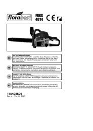
Illustration - Transaxle Assembly (Models ZTR <strong>308</strong> - <strong>311</strong>)
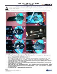
Illustration - Body Assembly (Models ZTR <strong>308</strong> - <strong>311</strong>)<br />
,- 41 «... ,L v
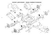
Illustration - Mower Deck Assembly 30" (Models ZTR <strong>308</strong> - <strong>311</strong>)