October 19-21, 1990 - Klofas.com
October 19-21, 1990 - Klofas.com
October 19-21, 1990 - Klofas.com

Create successful ePaper yourself
Turn your PDF publications into a flip-book with our unique Google optimized e-Paper software.
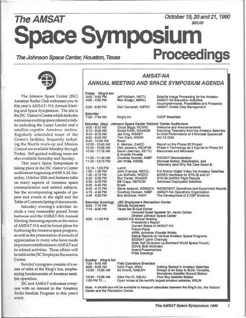
TheAMSAT<br />
Space<br />
The Johnson Space Center, Houston, Texas<br />
<strong>October</strong> <strong>19</strong>, 20 and <strong>21</strong>, <strong>19</strong>90<br />
$20.00<br />
peslurn<br />
•<br />
Proceedings<br />
AMSAT-NA<br />
ANNUAL MEETING AND SPACE SYMPOSIUM AGENDA<br />
The Johnson Space Center aSC)<br />
Amateur Radio Club wel<strong>com</strong>es you to<br />
this year's AMSAT- NA Annual Meeting<br />
and Space Symposium. The site is<br />
the JSC Visitor'sCenterwhichinciudes<br />
numerous exciting space related exhibits<br />
including the Lunar Lander and a<br />
satellite-capable Amateur station.<br />
Regularly scheduled tours of the<br />
Center's facilities, frequently including<br />
the Shuttle mock-up and Mission<br />
Control are available Monday through<br />
Friday. Self-guided walking tours are<br />
also available Saturday and Sunday.<br />
This year's Space Symposium is<br />
taking place in the JSC visitor's Center<br />
auditorium beginning at 8:00 A.M. Saturday,<br />
<strong>October</strong> 20th and features talks<br />
on many aspects of Amateur space<br />
<strong>com</strong>munication and related subjects.<br />
See the ac<strong>com</strong>panying agenda of papers<br />
and events to the right and the<br />
Table of Contents listing of documents.<br />
Saturday evenings activities include<br />
a very reasonably priced Texas<br />
barbecue and the AMSAT-NA Annual<br />
Meeting; featuring reports on the status<br />
of AMSAT-NA and its future plans for<br />
furthering the Amateurspaceprogram,<br />
as well as the presentation of awards of<br />
appreciation to many who have made<br />
important contributions to AMSA T and<br />
its related activities. These affairs will<br />
be held at the JSC Employee Recreation<br />
Center.<br />
Sunday's program consists of a series<br />
of talks at the Kings Inn, emphasizing<br />
fundamenlals of Amateur satellite<br />
operation.<br />
JSC and AMSAT wel<strong>com</strong>es everyone<br />
with an interest in the Amateur<br />
Radio Satellite Program to this year's<br />
event.<br />
Friday King'slnn<br />
3:00 - 3:50 PM Jeff Wallach, N51TU Satellite Image Processing for the Amateur<br />
4:00 - 4:50 PM Rich Ensign, N81WJ AMSAT-NA Education Activities:<br />
5:00 - 5:50 PM Dick Campbell, N3FKV<br />
Ac<strong>com</strong>plishments, Possibilities and Prospects<br />
AMSAT Orbital Data Management<br />
Saturday<br />
7:00 - 7:45 AM King's Inn CSDP Breakfast<br />
Saturday (day)<br />
8:00 - 8:10 AM<br />
8:10 - 8:35 AM<br />
8:40 - 9:15 AM<br />
9:20 - 9:40 AM<br />
9:40 - 10:00 AM<br />
10:00 - 10:40 AM<br />
10:40 - 10:55 AM<br />
10:55 -11:15AM<br />
11:20-11:4OAM<br />
11:40-12:15PM<br />
12:15·1:00PM<br />
1:00 - 1:35 PM<br />
1 :40·2:15 PM<br />
2:20 - 2:55 PM<br />
3:00 ·3:25 PM<br />
3:25 - 3:45 PM<br />
3:45 - 4:10 PM<br />
4:15 - 4:40 PM<br />
4:45 . 5:30 PM<br />
Saturday (evanlng)<br />
6:30 - 7:15 PM<br />
7:15 - 9:00 PM<br />
9:00 • 1 1:00 PM<br />
Johnson Space Center Visitor.' Center Auditorium<br />
Chuck Biggs, KC5RG Welccme and Announcements<br />
Gould Sm~h, WA4SXM Deccding Telemetry from the Amateur Satell
TheAMSAT<br />
Space Symposium<br />
Proceedings<br />
<strong>October</strong>, <strong>19</strong>90<br />
Editorial Coord/nato,.;<br />
Jack Crabtree. MDP<br />
Bill Tynan, W3XO<br />
Managing Edllor:<br />
Bob Myers, WtXT<br />
AMSAT·NA Board of Dlrecto,.:<br />
Tom Clarl
The Phase IV Project -A<br />
Transition to Phase 1110<br />
The Amateur <strong>com</strong>munity has not responded sufficiently to the Phase IV<br />
program financial needs to continue the spacecraft development at this time. The<br />
Phase IV technology that has been developed over the last three years is directly<br />
applicable, however, to the Phase IIIO program, proposed by ASMAT-OL. The<br />
global Amateur <strong>com</strong>munity can be well served by Phase IIIO, and AMSAT-NA<br />
expects to be playing a key role in this effort.<br />
By Dick Jansson, WD4FAB<br />
Phase IV Program Development Effort<br />
The Phase IV program development<br />
effort for the academic year (A Y) <strong>19</strong>89-90<br />
was conducted at Weber State College (soon<br />
to be called Weber State University) in<br />
Ogden, UT. This effort concluded the second<br />
year of such activity at Weber State,<br />
which has been very educational for the<br />
students, the school and for AMSAT-NA<br />
engineering personnel.<br />
Our efforts for A Y <strong>19</strong>88-89, reported at<br />
last year's Space Symposium, helped us<br />
evolve a basic spacecraft frame for one<br />
concept ofa Phase IV calleda"pass through"<br />
structure, see Fig. 1. Spaceaaft structural<br />
concepts will be discussed later in this paper.<br />
This past year's efforts were aimed at<br />
building upon that base of information and<br />
to add some important items to the structure.<br />
At the start of the academic year, the program<br />
plan included the following major<br />
goals:<br />
1. Develop the design andmanufacturing<br />
techniques for deployable antenna arrays<br />
for the spacecraft.<br />
2. Develop a Finite Element structural<br />
Analysis technique to be employed as an<br />
engineering design tool.<br />
3. Develop the manufacturing techniques<br />
for fabricating and installing spacecraft<br />
system subassemblies.<br />
4. Evaluate improvements in materials<br />
and fabrication methods of the spaceframe<br />
structural elements.<br />
We did not achieve aU of these goals,<br />
but the achievements that were made on<br />
items 1 and 2 were significant and worthy.<br />
The proof of the effort was in performing a<br />
low frequency vibration test of the antenna<br />
structural elements on the Top Plate of the<br />
spacecraft.<br />
Program Ac<strong>com</strong>plishments<br />
A great deal was learned in the engineering<br />
and fabrication of light weight<br />
<strong>com</strong>posite spacecraft structures. A simplified<br />
tubular design of the microwave Helical<br />
antenna for L and 5 band operation was<br />
evolved and shown in The ARRL Handbook,<br />
<strong>19</strong>90 edition, Chapter 23. The design lent<br />
itself to being fabricated of thin walled fiberglass-epoxy<br />
<strong>com</strong>posite material that is<br />
readily formed on standard machinery used<br />
for making ski poles, etc. Antenna supporting<br />
struts were also similarly formed of<br />
both fiberglass and carbon fiber epoxy<br />
<strong>com</strong>posites and are shown during assembly<br />
in Fig. 2.<br />
The assembled Phase IV spacecraft Top<br />
Plate with the antenna structures in the<br />
(latched) launch position is shown in Fig. 3,<br />
and in the on-orbit deployed position in<br />
Fig. 4. The long black tube seen in these<br />
assemblies is the 2.8m (9ft.) long UHF antenna<br />
boom, shown here without elements.<br />
Compression moulded UHF antenna element<br />
mounts were fabricated as part of this<br />
project, but not used in these particular<br />
assemblies. Seen in these illustrations is a<br />
light weight aluminum supporting frame<br />
for the Top Plate which provided excellent<br />
access to working on the Top Plate without<br />
being bothered with having the main<br />
spacecraft structure in the way. Not illustrated<br />
here is a large overhead lifting assembly<br />
that was built by students to permit<br />
the maneuvering of the entire assembled<br />
Top Plate from the spacecraft and to place it<br />
onto the support frame. This lifting device<br />
also permitted the rotation of the Top Plate<br />
so that either side would be avallable for<br />
assembly activities. Fig. 5 shows the entire<br />
spacecraft with the Top Plate and antennas.<br />
Another item that was needed for the<br />
program was an adaptor frame to interface<br />
the Top Plate assembly to the large shaker<br />
facility at the Air Force's Little Mountain<br />
Survivability & Vulnerability Test Center,<br />
located near Ogden, UT. The installation of<br />
this shaker adaptor is shown in Fig. 6. The<br />
environmental area of interest for this test<br />
was the vibration regime below 200 Hz, the<br />
adaptor did not need to be excessively massive<br />
and was formed from 4 in. channel<br />
aluminum stock.<br />
The Top Plate assembly is shown in<br />
Fig. 7 being lifted onto the shaker table by<br />
many hands, and in Fig. 8 ready for test.<br />
The actual shake test was almost anticlimactic<br />
in the process of just getting the test<br />
article to the facility, although some of the<br />
Fig. 1 - 3-D view of Phase IV as might appear In orbit. Fig. 2 - Phase IV tubular support strut sub-assemblies.<br />
The AMSAT Space Symposium <strong>19</strong>90 3
I<br />
Fig. 3 - Phase IV Top Plale Assembly wllh anlennas In lalched<br />
launch position.<br />
Fig. 4 - Phase IV Top Plale Assembly wHh anlennaa In deployed<br />
position, student Ken HIli Inspecting the assembly.<br />
antenna parts did get pretty exdted in the<br />
process.<br />
This FEA analytic technique, that was<br />
sponsored as part of the Weber State effort,<br />
is a <strong>com</strong>puter structural analysis technique<br />
that predicts spacecraft responses to dynamic<br />
mechanical vibration environments,<br />
such as those induced by launch vehicles.<br />
Getting into the FEA activities involved<br />
another department in the school of Engineering<br />
Technology, at Weber State, and<br />
another set of students doing that part of<br />
the project. This was a timely effort, as we<br />
had some of the real hardware for them to<br />
examine and evaluate, allowing a feel-andtouch<br />
addition to an otherwise paper analytic<br />
activity.<br />
The logical conclusion of these two<br />
efforts was a mechanical shaker test of the<br />
antenna structures to see how their responses<br />
agreed to the FEA predictions. Fig.<br />
9 shows the predicted vibration frequencies<br />
for several sizes of supporting shuts.<br />
The model that was shaken used 25mm<br />
diameter struts and the L antenna was excited<br />
into a severe resonance at <strong>19</strong>.5 Hz, not<br />
far from the predicted 1st mode resonance<br />
projected by the FEA. The UHF antenna<br />
assembly also had a pronounced resonance<br />
at 25 Hz. Typical launch vehicle requirements<br />
are that the payloads have no vibration<br />
responses below 50 Hz, as the primary<br />
launch vehicle mode is in the 35 Hz range.<br />
Clearly, AMSAT engineering needs to do<br />
more work in stiffening the antenna supports<br />
and a substantial improvement in the<br />
antenna restraint hardware and methods,<br />
needed for launch. The entire effort was<br />
very educational.<br />
In addition to evolving spacecraft design<br />
elements and techniques, applicable to<br />
nearly any moderately sized spacecraft, we<br />
have also added some very useful management<br />
and software tools. Program planning<br />
and progress tracking <strong>com</strong>puter software<br />
tools have been usefully employed in<br />
the Phase N program effort this year. While<br />
such steps may seem superfluous for this<br />
effort, the Weber State program had a considerable<br />
amount of <strong>com</strong>plexity and the<br />
resulting Gantt chart had 82 elements. Using<br />
such tools, however, requires a considerable<br />
degree of dedication by all personnel.<br />
and the management information so<br />
generated is only as good as the data input.<br />
The degree of dedication required is no<br />
different than that required in the <strong>com</strong>merdal<br />
work place. Obtaining such attention<br />
in the student academic environment<br />
is another matter, despite good intentions<br />
on the part of all parties. For all parties, this<br />
has also been quite an educational process.<br />
Aside from the program planning<br />
Fig. 5 - Phase IV Top Mounled onlo spacecraft. Fig. 6 - Students mounting shaker adaptor structure to<br />
shaker table.<br />
4 The AMSAT Space Symposium <strong>19</strong>90
.......<br />
Rg. 7 -All hands mounting Top Plate assembly to shaker. Prolect<br />
student leader. Tracy Rose Is on top of the Job.<br />
Fig. 8 -<br />
Phase IV Top Plate mounted to shaker ready for test.<br />
software, noted above, and an upgrade in<br />
the AutoCAD software used for designing<br />
AMSAT spacecraft, some major improvements<br />
have been made in the thermal design<br />
area. A Thermal Analysis Work System<br />
(THAWS) package has been made<br />
available for us by Weber State College.<br />
This software package has a large, fast<br />
version of the SIND A thermal analyzer that<br />
has been used on Microsat and the Phase IV<br />
analyses done to date. The size and speed<br />
increases will be very useable for <strong>com</strong>plete,<br />
<strong>com</strong>plex model Phase IV (and other spacecraft)<br />
analyses. This analytic capability was<br />
demonstrated on a non-AMSAT spacecraft<br />
project in early <strong>19</strong>90. THAWS also has a<br />
very sophisticated thermal radiation interchange<br />
<strong>com</strong>putation capability, which is an<br />
absolutely essential part of a spacecraft<br />
thermal analysis. It is expected that we will<br />
have a precise knowledge of thermal performance<br />
for any future spacecraft long<br />
before they are launched. We will not have<br />
any hot batteries, as was the case with OS<br />
CAR 7.<br />
The Phase 1110 Program<br />
Other papers at this Symposium will<br />
discuss the Phase II1D mission and operations.<br />
It is useful to discuss herein the<br />
possible configurations for such a space-<br />
-- ,.. .......<br />
___ ~d<br />
_______ 3nI ......<br />
& T .... Do,.<br />
craft. These possibilities boil down to two<br />
structural candidates. Based upon the<br />
launch vehicle constraints these are: a passthrough<br />
deSign, very much like the Phase<br />
IV design studied to date (see Fig. 1); and a<br />
stand-alone design that does not contain<br />
parts of the launch vehicle within its shell.<br />
As we have studied the pass-through<br />
design extensively, and we are prepared to<br />
implement such a design if needed, we<br />
have not done any equivalent studies on the<br />
stand-alone design. Fig. 10 is an engineeringdrawing<br />
for this design, which has been<br />
termed (witha little tongue-in-cheek) a cubic<br />
2 meter. Indeed the internal volume is just<br />
about 2m 3 and it has the power generation<br />
capabilities of 3m l of solar panel area, or<br />
about 300 Watts, six times that of OSCAR<br />
13. Figs. 11 and 12 are two views of a three<br />
dimensional drawing of this configuration.<br />
There are a number of advantages to<br />
the stand-alone configuration of spacecraft<br />
that seriously argue for its use. This design<br />
would only require 32% of the solar cells of<br />
the cylindrical spacecraft, as they would be<br />
actively oriented for optimum power generation.<br />
This would represent a significant<br />
cost saving. Spacecraft mass is another<br />
issue. The pass-through design is burdened<br />
by some 45+kg of launch vehicle hardware<br />
and an added 35+kg of added solar panels<br />
and cooling heat pipes. All of these added<br />
masses require a corresponding increase in<br />
propellant mass l used to get the spacecraft<br />
to its final orbit. Itwould be difficult to have<br />
a pass-through design spacecraft any less<br />
than a launch mass of 400kg and more<br />
probably it would be 450+kg. The standalone<br />
spacecraft design could be as low as<br />
200kg. but it will probably be sized for an<br />
expected 250kg launch mass.<br />
The global AMSAT design team is<br />
Fig. 9 - L band antenna vibration<br />
performance predictions.<br />
! F--~B:$!fF -j<br />
L._ ••. ~ _ •.. ~<br />
Fig. 10 -<br />
Engineering drawing of PhaselliD "Configuration Study."<br />
TheAMSATSpaceSymposlum <strong>19</strong>90 5
F1g.11-3-0 view of Pha.eIllO. Flg_ 12 - Another 3-D view of Phase 1110.<br />
studying many aspects of this mission and<br />
it is a really fun part of Amateur radio.<br />
Within AMSAT-NA we are studying<br />
(among other aspecls) the mechanical and<br />
thermal designs of such a spacecraft. As a<br />
result of the engineering networking done<br />
on the Phase IV project, we have members<br />
studying the mechanisms for deployment<br />
and rotation of the solar panels. Our team<br />
is also assembling preliminary FEA models<br />
to guide the initial structural designs, and<br />
antenna issues. The illustrations shown on<br />
these views of Phase IUD contain the tubular<br />
Helical antenna design of Phase IV, but<br />
in a fixed, non-deployable configuration.<br />
Recent investigations have brought to light<br />
some possibly useful CP antenna designs<br />
that could be implemented on a flat printed<br />
circuit board.<br />
Conclusions<br />
Engineering efforts on the Phase IV<br />
project have given us alotofinsightinto the<br />
construction of "small" satellites that are<br />
clearly larger than the early OSCARs and<br />
the Microsals. While we had hoped to find<br />
enough support for us to get one of these<br />
satellites into a geostationary orbit, it does<br />
not appear that we will be able to achieve<br />
that goal.<br />
The Phase IIIDproject provides us some<br />
really new opportunities to show the satellite<br />
world that AMSAT is truly THE small<br />
satellite innovator and leader in satellite<br />
<strong>com</strong>munications technology. Our engineering<br />
experience with Phase IV is very<br />
directly applicable to Phase IIID.<br />
AMSAT Orbital Data<br />
Management<br />
By Dick Campbell, N3FKV<br />
AMSAT Operational Coordinator for<br />
Orbital Data Managsment<br />
Nothing is nearer and dearer to the<br />
heart of a satellite chaser than a current set<br />
of accurate Keplerian orbital elements.<br />
AMSA T responded to this need as personal<br />
<strong>com</strong>puters began to proliferate in Ham<br />
shacks, pushing aside the OSCARLocatoras<br />
the primary satellite tracking means. The<br />
first programs were limited in capability,<br />
and data entry was ac<strong>com</strong>plished manually<br />
by most users. Vern Riportella, W A2LQQ,<br />
then President, began the original distribution<br />
of the AMSAT element set format<br />
via the weekly Nets and the AMSAT Amateur<br />
Satellite Report (ASR). The format with<br />
which everyone is now familiar grew Qut of<br />
a desire to make the two line element sets<br />
distributed by NASA an easily readable<br />
tool for the manual user.<br />
The Keplerian numbers do not appear<br />
out of thin air, of course. NORAD has the<br />
nission to keep track of all objects in orbit,<br />
and it is their radar tracking that generates<br />
the weekly data. This is passed to NASA for<br />
further distribution to the public. Anyone<br />
can obtain a printed weekly listing simply<br />
by asking, but this is a service provided by<br />
AMSA T to all. With the advent of packet<br />
6 The AMSAT Space Symposium <strong>19</strong>90<br />
radio and the growth of that distribution<br />
network, it was logical to proceed to an<br />
electronic fonnat. Two new volunteers<br />
emerged on the scene, Courtney Duncan,<br />
NSBF, and Ralph Wallio, W0RPK.<br />
Couriney would write the software to create<br />
the bulletins and Ralph would see that<br />
they were put together every week for distribution.<br />
For the past several years, you<br />
would have been quite familiar with Ralph's<br />
call sign if you were catching the weekly<br />
AMSAT orbital bulletins. The hard part of<br />
all this - element sets still had to be transcribed<br />
manually from the NASA mailings.<br />
Certainly it was a tedious undertaking, and<br />
inefficient in this day of ""workaholic llll PCs,<br />
but necessary nonetheless.<br />
Call For OOM<br />
In late <strong>19</strong>89, Ralph was unable to continue<br />
the weekly chore as Orbital Data<br />
Manager, and the duty fell to Courtney,<br />
who had assumed duties as the Vice President<br />
of Operations in the meantime. When<br />
he called for help, I raised my hand (I obviously<br />
had been listening to too much telemetry)<br />
and took over the weekly duties of<br />
distributing AMSA T element sets to the<br />
world. The good news was that now all<br />
element sets were available electronically<br />
from T.S. Kelso and his Celestial BBS. He is<br />
partidpatingin a pilot program with NASA<br />
for their eventual electronic mailing system.<br />
The bad news was that all sets from<br />
Celestial were in the 2-line format and no<br />
software or standard existed to guide me in<br />
the conversion. Those first few releases<br />
generated several howls from software users<br />
whose files would crash because of extra<br />
white space, carriage returns, and extraneous<br />
text. However, once those bugs were<br />
identified, I was able to put together a<br />
software package that makes the whole<br />
process automatic and relatively painless,<br />
and is <strong>com</strong>patible with existing tracking<br />
programs.<br />
This automated distribution software<br />
is written in C and <strong>com</strong>piled BASIC, and is<br />
running on an 05-9 system. Once the elements<br />
are downloaded from Celestial BBS,<br />
the AMSAT birds are sorted out and the<br />
checksum of the NASA 2-line is verified.<br />
Then the sets are translated into the AMSA T<br />
human readable text and packaged into the<br />
packet bulletin format we all know and<br />
love. I then place this file on AMSAT's<br />
electronic mail service where it is picked off<br />
by a host of dedicated volunteers, packet<br />
sysops, Net Controls and the OSCAR Satellite<br />
Report (ASR's unofficial successor). This<br />
gets the weekly bulletins into the networks<br />
and on the air for your use. The whole<br />
process takes about 30 minutes, hands off.<br />
My final act is to archive that week's<br />
file in the event elements are needed for<br />
research, such as the recent AO-13 orbit<br />
studies. I am retaining all element sets I
hare gl""""':P
tion of perigee .t the epoch time.<br />
h. Mean Anomaly: This angle is<br />
measured forward in the orbit from perigee<br />
to the satellite position, zero to 360 degrees.<br />
In a circular orbit, it is the number of degrees<br />
from perigee around the circle. Remember<br />
we said that the RA of node was the position<br />
of the satellite at the epoch time. In other<br />
words, the satellite is at the equator at this<br />
time. Therefore, the mean anomaly in this<br />
set will also be the angle from perigee to the<br />
equator. This means that, for circular orbits<br />
only, the sum of argument of perigee and<br />
mean anomaly will always be equal to 360<br />
degrees (plus or minus a small fraction due<br />
to the slight eccentricity). This is another<br />
check you can make, but it is only valid for<br />
those normalized sets promulgated by<br />
NASA.<br />
L Mean Motion: the number of revolutions<br />
(orbits) the bird makes in one solar<br />
day. Dividing this number into 1440 minutes/<br />
day will give you the orbital period in<br />
minutes. It should not vary to two or three<br />
decimal places, unless the spacecraft is<br />
conducting orbital maneuvers, such as the<br />
Space Shuttle or Mir, or if it is near re-entry.<br />
j. Decay Rate: the first derivative with<br />
respect to time of the mean motion. Its<br />
magnitude varies inversely with the satellite<br />
altitude. This parameter will have a<br />
How Can I Help?<br />
AMSAT-NA Operations<br />
very small effect on your output, but can<br />
skew results if you are using a set that is<br />
several months old. Simply make this value<br />
zero in your tracking program if you have<br />
an old set, and your solution will be close<br />
enough fornonnal amateur operations. 1bis<br />
value represents all of the urunodeled but<br />
observed perturbation factors in an orbit.<br />
For a new launch, it is useful only after<br />
several weeks of data are taken.<br />
k. Epoch Rev: the revolution or orbit<br />
number for the given epoch time. It is a nice<br />
number to put on your QSL card and tells<br />
you something about the age of the satellite,<br />
but it does not enter into tracking <strong>com</strong>putations.<br />
The orbit number theoretically increments<br />
at perigee, but NASA increments<br />
at ascending equator crossings. Significant<br />
differences will be seen only in the low orbit<br />
birds, whose perigee precession laps the<br />
equator more often.<br />
The Future<br />
What is in the future for AMSAT orbital<br />
data? With the Microsats and FO-20<br />
flying high and providing good signals, it<br />
would be relatively easy to include each<br />
bird's own current elements in its beacon.<br />
Software could automatically read that<br />
transmission and update your tracking<br />
software. Establishing a corps of volunteers<br />
AMSAT-NA Operations has initiated or continued several membership seroice<br />
and involvement programs during the past year. They include: AMSAT News<br />
Seroice: Dave Cowdin (WD0HHU) Director; Command Station Development<br />
Program: Bruce Rahn (WB9ANQ) Coordinator; Digital Gateways: Harry Morton<br />
III (WB2IBO) Coordinator; DX Operation: John Fail (KL7GRF/6) Coordinator;<br />
HFNets: WrayDudley(VV8GQWf1)Manager; OperationsNet (AO-13): Courtney<br />
Duncan (N5BF/6) Acting Manager; Orbital Data Management: Dick Campbell<br />
(N3FKV/5) Coordinator; PacsatManagement: Courtney Duncan (N5BF), Trustee;<br />
Software Exchange: (manager position currently vacant); Telemetry Archive: Reid<br />
Bristor (VVA4UPD) Coordinator; and Telephone BBS Network: John Wisniowski<br />
(N6DBF) Coordinator. Expansion of these and other programs and projects is<br />
planned. In this talk, these Operations activities will be discussed and those not<br />
covered in their own Symposium talks will be presented in greater detail. Discussion<br />
from the floor is wel<strong>com</strong>e.<br />
By Courtney B. Duncan, N5BF<br />
AMSAT-NA VP Operations<br />
Introduction<br />
One of the most <strong>com</strong>mon questions<br />
asked by new AMSAT members and old<br />
hands alike is, "What can I do to help out?"<br />
Making an effective contribution to an organization<br />
depends largely on knowing<br />
B The AMSAT Space SymposIum <strong>19</strong>90<br />
what needs it has <strong>com</strong>pared to the talents,<br />
skills, and time the members have; being<br />
able to connect them together; and being<br />
realistic about all of them. In this paper, I'll<br />
describe several ongoing projects within<br />
AMSAT-NA Operations where satellite<br />
to track and check the elements we release<br />
would validate our data and could even<br />
lead to a capability to <strong>com</strong>pute our own<br />
element sets, a technlcal challenge that may<br />
be appealing to some. On the bulletin side,<br />
I will investigate modifying the release<br />
schedule so that current sets are available<br />
only as often as necessary for the type of<br />
orbit, thereby relieving congestion on the<br />
distribution network. There will be many<br />
fun things to do, but all requiring volunteers<br />
who like to write software, reduce telemetry,<br />
operate packet and landline BBSs, or verify<br />
orbits. I will be receptive to all takers, and<br />
if you have a favorite bird you would like to<br />
start watching, let me know and I will get<br />
you involved. My first real requirement is<br />
for an assistant or two, someone who can<br />
also pick up the weekly duties on occasion<br />
(so I can go on vacation and you still get<br />
your data!).<br />
All in all, I have really enjoyed this job<br />
and hope you will get involved too. We are<br />
part of a great organization and it needs<br />
your active support. We have a challenging<br />
future ahead of us as we upgrade our capabilities.<br />
Catch me Non the birds", I look<br />
forward to meeting you and discussing these<br />
issues.<br />
operators can be involved from their own<br />
stations. I'll also briefly mention AMSAT<br />
NA Field Operations and AMSAT-NA Engineering<br />
as areas where participation is<br />
possible. Of course, no list like this can be<br />
exhaustive but the intention here is as much<br />
to inspire new ideas and suggestions as to<br />
advise about current opportunities.<br />
As AMSAT continues to evolve and<br />
personnel <strong>com</strong>e and go, the names and<br />
contact points will, naturally, change. For<br />
the latest information on contacts, contact<br />
me directly or contact AMSAT-NA Headquarters.<br />
lam:<br />
Courtney Duncan, N5BF<br />
AMSAT-NA Vice President Operations<br />
4522 Ocean View Blvd.<br />
La Canada, California 91011-14<strong>19</strong><br />
Headquarters is:<br />
The Radio Amateur Satellite<br />
Corporation<br />
p. O. Box 27<br />
Washington, DC 20044<br />
301-589-6062<br />
So, what can you do to help out? It<br />
depends basically on two things: Where are<br />
you (geographically, temperamentally, financially,<br />
in terms of training and abilities,<br />
amateur radio, amateur equipment, satellite<br />
equipment) and what are your interests.<br />
This second question - What are your inter-
The Aulhor, N5BF, shown al his operating posilion.<br />
ests - may seem simple l but for most it is the<br />
most difficult and elusive question of all,<br />
particularly in volunteer settings.<br />
In deciding what you would like to do<br />
to help out, think about what you are doing<br />
now. When you have free moments for<br />
your hobby, what do you do? Do you<br />
design circuits? Work on kits? Make contacts<br />
on the air? Pass traffic or run phone<br />
patches? Go to club meetings or conventions?<br />
Write articles? Write software?<br />
Chances are your best areas of service will<br />
be extensions of activities you already enjoy<br />
and already know something about how<br />
todD.<br />
For the past couple of years, several of<br />
us in AMSAT Operations have been working<br />
to make the whole process of getting<br />
involved and of making important contributions<br />
to the amateur satellite cause somewhatless<br />
painful, though it is not yet totally<br />
painless. The idea is to consciously think<br />
about what needs to be done and how itcan<br />
be ac<strong>com</strong>plished, then to set up programs<br />
designed to make the incremental steps<br />
smaller, the individual encouragement<br />
greater, and the overall product coordinated.<br />
Operations<br />
AMSAT Operations <strong>com</strong>prises many<br />
diverse departments en<strong>com</strong>passing virtu~<br />
ally everything not handled by Engineering.<br />
the branch that builds the satellites and<br />
gets them launched; Field Operations, the<br />
branch thai represents AMSAT at hamfests<br />
and provides localized Elmering; and<br />
business management.<br />
(1) AMSAT News Service: Dave<br />
Cowdin, WD0HHU, Director<br />
The people involved with the AMSAT<br />
News Service (ANS) collect information<br />
about amateur radio space activities (pri~<br />
marily amateur satellite and manned space<br />
projects), <strong>com</strong>pile them weekly, and provide<br />
a set of bulletins that are distributed<br />
via packet radio and telephone bulletin<br />
boards, and that are read on various AMSAT<br />
nets. The news sources are generally reports<br />
from electronic mail users, personal contacts,<br />
trips, and occasionally other amateur<br />
publications. Due to attrition and the fact<br />
that ANS bulletins are expected every week,<br />
though some of the writers have jobs, personallives,<br />
and vacations to attend to, there<br />
is always a need for more reporters.<br />
To volunteer, contact:<br />
Dave Cowdin, WD0HHU<br />
8325 S. Yukon SI.<br />
Littleton, Colorado 80123-6144<br />
(2) Command Station Development<br />
Program: Bruce Rahn, WB9ANQ, Technical<br />
Coordinator<br />
Up until AMSAT-OSCAR 16 was<br />
launched in January of this year, AMSAT<br />
N A had not been the lead organization in<br />
charge of operating a satellite mission in<br />
over a decade. Furthermore, satellite main~<br />
tenance, though somewhat glamorous and<br />
shrouded in high-tech mystery, is actually a<br />
nitty-gritty job requiring the utmost devotion<br />
for long periods of time. In short, it is<br />
normal to burn out amateur <strong>com</strong>mand stations.<br />
Meanwhile, many "middle level"<br />
jobs that require some technical <strong>com</strong>petence<br />
and could be very interesting and<br />
beneficial to the whole satellite <strong>com</strong>munity<br />
simply don't get done because the <strong>com</strong>mand<br />
personnel are too busy keeping up<br />
with satellite operation and no one else<br />
knows what needs to be done. Also, the<br />
working structure within AMSAT-NA is<br />
rather intimate and intense. Thus, it is often<br />
difficult for new volunteers to over<strong>com</strong>e<br />
the personal and technical obstacles that<br />
exist between the state of being a satellite<br />
enthusiast and the state of being an integrated<br />
participant in the overall program.<br />
The Command Station Development<br />
Program (CSDP) was established to address<br />
these issues. TIrrough a series of<br />
challenging. graded "Levels: a candidate<br />
operator progresses from the basic ability<br />
to make contacts on or with satellites,<br />
through an overview of satellite telemetry<br />
and maintenance, culminating in a specialization<br />
in some area of study or performance<br />
of interest to both the operator and<br />
AMSA T. They are expected to be the main<br />
sources of in-depth information about satellite<br />
operation and status in AMSAT within<br />
their special areas of concentration.<br />
This has really worked well. Several<br />
current project coordinators and other key<br />
Operations volunteers were initiaUyidentified<br />
and tasked as a result of CSDP applications.<br />
Several others have been able to<br />
make important contributions that would<br />
have been much more difficult without the<br />
CSDP structure. CSDPis the place forthose<br />
wanting to face the big technical and political<br />
challenges to find out just how involved<br />
in the amateur satellite program they really<br />
Typical Slalion.<br />
.. Iiiifa I<br />
The AMSAT Space Symposium <strong>19</strong>90 9
Field Day antennas.<br />
can be.<br />
To volunteer, send an SASE to:<br />
Bruce Rahn, WB9ANQ<br />
410 Coronado Trail<br />
Enon, Ohio 45323<br />
(3) Digital Gateways: Harry Morton<br />
III, WB2IBO, Technical Coordinator<br />
With the advent this year of four new<br />
satellites intended primarily for use as<br />
"PACSATs," UO-14, AO-16, LO-<strong>19</strong>,andFO-<br />
20, one of the main uses envisioned for the<br />
first three is to serve as the medium for<br />
worldwide packet mail forwarding and<br />
bulletin dissemination. Also, DO-17 and<br />
WO-18 are expected to transmit digital information<br />
of a general or educational nature.<br />
As the protocols, special techniques,<br />
and software are now under development<br />
for these tasks, the Digital Gateways project<br />
isin its infancy. WB2IBO is currently maintaining<br />
a list of stations worldwide who<br />
would like to configure as Earth-to-satellite<br />
gateway nodes, and he will be working<br />
with them to get the nodes established and<br />
into operation as the techniques develop.<br />
Though a little out of the individual operator-to-satellite<br />
tradition in the satellite service,<br />
Digital Gateways promise to have an<br />
impact on amateur radio as great as any<br />
\hing ever done with satellites. And, now is<br />
the time to get in on the ground floor.<br />
To participate, contact:<br />
Harry B. Morton, III, WB2IBO<br />
261 N. Chestnut Street<br />
North Massapequa, NY 11758<br />
(4) DX Operation: John FaiL<br />
KL7GRF / 6, Operational Coordinator<br />
One of the biggest avocations within<br />
the world of amateur radio is DXing. We<br />
can tell that amateur satellite operation is<br />
beginning to make inroads into the mainstreams<br />
of amateur radio because of the<br />
increasing popularity of operational activities<br />
like DXing. KL7GRF / 6 is a central<br />
figure in a widespread effort to encourage,<br />
enable, and EImer satellite operators in DX<br />
locations, including both DXpeditions and<br />
local permanent residents. Currently, over<br />
120 countries are represented among the<br />
thousands of AO-13 and AO-IO operators<br />
worldwide. Several amateurs have earned<br />
satellite DXCC or even AO-13 DXCC. In<br />
tackling this hefty challenge, the DX intensive<br />
operators provide considerable general<br />
and popular support for AMSAT<br />
projects and pragmatic knowledge of satellite<br />
operating conditions and access windows.<br />
The best way to get involved in satellite<br />
DXing is to just show up on AO-I0 or AO-<br />
13 Mode B on 145.890 MHz, or on AO-13<br />
Mode J /L on 435.960 MHz, and simply join<br />
the group. Or, contact:<br />
John Fail, KL7GRF / 6<br />
6170 Downey Ave.<br />
Long Beach, California 90805<br />
(5) HFNets: Wray Dudley, W8GQW /7,<br />
Manager<br />
Camaraderie and information are importantto<br />
AMSAT members as is AMSAT's<br />
exposure to active amateur radio operators<br />
who are not yet satellite operators. For this<br />
reason, AMSAT manages or recognizes<br />
several regional HF and localized VHF /<br />
UHF nets around North America and<br />
around the world. As with the AMSAT<br />
News Service, running a net week after<br />
week, or running it alone, can prove to be a<br />
difficult personal burden. There is always<br />
a need, therefore, for new Net Control and<br />
OSCAR Field Oay setup.<br />
Bulletin Stations to service and back up the<br />
vast array of AMSAT nets. The AMSAT<br />
Netin your region or local area undoubtedly<br />
needs extra Bulletin Stations or Net Control<br />
Stations for the rotation, and if your region<br />
or local area doesn't have an AMSA T net, it<br />
should!<br />
If your station is adequate to the task of<br />
supporting a net and if you are so inclined,<br />
this is an important way in which you can<br />
help out and be on the leading edge of the<br />
AMSAT information all at once.<br />
Contact:<br />
Wray Dudley, W8GQW<br />
P. O. Box 15<strong>21</strong><br />
Tubac, Arizona 85646<br />
(6) Operations Net (AO-13): Courtney<br />
Duncan, N5BF / 6, Acting Manager<br />
With the advent of hemispherical<br />
coverage satellites like AO-I0 and AO-13,<br />
hemispherical nets and round tables have<br />
now be<strong>com</strong>e possible. Although these<br />
Molniya-orbit transponders do not allow<br />
the convenience of a net" every Saturday at<br />
7 p.m.; it is still possible to draw and<br />
maintain a crowd on a regular basis on<br />
these satellites. The AMSA T -NA Operations<br />
Net exists for the purposes of demonstrating<br />
that this can be done, assisting and<br />
informing participants, and acquainting<br />
satellite operators with each other and with<br />
AMSA T managers. Over 250 different stations<br />
have participated in over 50 sessions<br />
over a period of two years. Topics have<br />
ranged from satellite DJung, to Mode S, to<br />
general round tables and late breaking news.<br />
We hope that other nets with different<br />
purposes or in different geographic locations<br />
will be established on the satellites<br />
follOwing the model of the existing Operations<br />
Net.<br />
The Operations Net is in need of volunteers<br />
for Net Manager and Net Control<br />
10 The AMSAT Space Symposium <strong>19</strong>90
SGfiondnty. nus isanoiher oppartuni!y to<br />
getin
The process of building a satemte.<br />
ing can be done with a VOM.<br />
Power generation at microwave frequencies<br />
is still expensive but, because of<br />
the elegance, simplicity, and low cost of the<br />
MMIC-with-PCB-filter technology, I now<br />
re<strong>com</strong>mend that satellite operators contemplating<br />
the next move beyond the basic<br />
Mode A/BI] capability go next to Mode S.<br />
As with all weak signal work, good preamplification<br />
is required, but antennas are<br />
simple and good success with a 2.4 GHz<br />
receive converting system is easily within<br />
reach for anyone now able to operate Mode<br />
B. Further, this is another investment in the<br />
future. Most new satellite projects now<br />
being planned will include and even emphasize<br />
2.4 GHz downlinks.<br />
AMSA T also wel<strong>com</strong>es discussions<br />
with other organizations and other hobbyists<br />
with similar goals. Forexample, AMSAT<br />
may provide amateur radio <strong>com</strong>mand and<br />
telemetry equipment for an experimental,<br />
non-profit, solar sail demonstration vehicle<br />
under development by the World Space<br />
Foundation with sponsorship from the<br />
Planetary Society and other organizations.<br />
]fyau are connected with an educational or<br />
non-profit institution or project like this<br />
and think that cooperation with AMSAT<br />
might be mutually beneficial, speak up!<br />
As you can see, virtually all departments<br />
within AMSAT Operations need<br />
additional workers, leaders, and innovators.<br />
Field Operations<br />
Field Operations is the organization<br />
withinAMSAT -NA that <strong>com</strong>prises our main<br />
hlterface to the rest of amateur radio in<br />
general. Active satellite operators in various<br />
geographic areas throughout North<br />
America (Canada, Mexico, and the U. S.)<br />
are appointed "Area Coordinators" for<br />
AMSAT-NA. They then represent AMSAT<br />
by giving talks at club meetings; sponsoring<br />
booths featuring AMSAT demonstrations<br />
and materials at nearby hamfests,<br />
conventions, and swap meets; passing out<br />
information on local and regional nets (HF<br />
and VHF); and making themselves generally<br />
available as satellite "Eimers" within<br />
their area.<br />
The "Areas" (usually defined by the<br />
QTH of the Area Coordinator and the distance<br />
he is willing to drive to do these<br />
duties) are grouped into several regions on<br />
the continent which are managed by Regional<br />
Coordinators. These in turn report<br />
to the AMSAT-NA Vice Presidentfor Field<br />
Operations, Jack Crabtree, AA0P, who is<br />
appointed by the AMSAT-NA Board of<br />
Directors. Regional and Area Coordinators<br />
also work closely with Martha Saragovitz,<br />
the AMSAT-NA Headquarters Office<br />
Manager, arranging for AMSAT materials<br />
which are distributed for donations at<br />
amateur radio meetings and conventions.<br />
To volunteer as an Area Coordinator,<br />
contact:<br />
Jack Crabtree, AA0P<br />
AMSAT-NA Vice President for Field<br />
Operations<br />
4327 West Bellewood Dr.<br />
Littleton, Colorado 80123<br />
Engineering<br />
Most amateur satellite enthusiasts are<br />
fascinated by the prospect of working on a<br />
piece of hardware that will actually fly in<br />
space, then potentially being able to use it<br />
once in orbit. This is sometimes seen as the<br />
"ultimate trip" within AMSAT. You have<br />
read by now that now that there is much<br />
more to the Radio Amateur Satellite Service<br />
than designing, building, and launching<br />
satellites and that there are many ways to be<br />
involved as deeply as you want and have as<br />
much fun as you want without ever getting<br />
near any orbiting hardware. There are some<br />
peculiarities to the satellite construction<br />
business that you should know about, but,<br />
if you are in the right place at the right time<br />
with the right abilities, you too can help to<br />
"build a bird."<br />
Satellite construction tends to be much<br />
more geographically localized than satellite<br />
operation does, though the trend recently<br />
has been away from this whenever possible.<br />
The Microsats, for example, were designed<br />
and built in modules all over North<br />
and South America. The receivers were<br />
designed and prototyped by Tom Clark,<br />
W3IWI, in Maryland. The power modules<br />
were designed and prototyped at ARRL<br />
Headquarters in Connecticut by Jon Bloom,<br />
KE3Z. Thermal and mechanical design and<br />
speCification and most of the working<br />
drawings were done by Dick Jansson,<br />
WD4F AB, in Florida. The <strong>com</strong>puters were<br />
designed and constructed by Lyle Johnson,<br />
WA7GXD, with significant assistance from<br />
over a dozen other people. The transmitters<br />
were designed and prototyped in<br />
Colorado by Mataj Vidimar, YT3MV, a<br />
visiting Rhodes Scholar from Yugoslavia.<br />
Spedal Microsat "payloads" came from<br />
Argentina, Utah, and other locations. Much<br />
of the mechanical work was done at Weber<br />
State University, which was, of course,<br />
sponsoring its own satellite, WEBERSAT.<br />
Assembly actually spanned North<br />
America in several marathon sessions. Integration<br />
occurred in the AMSAT-NA lab<br />
in Boulder and space qualification testing<br />
was done in <strong>com</strong>mercial facilities donated<br />
by Martin Marietta, Littleton, Colorado, a<br />
deal arranged by a key AMSAT volunteer,<br />
Jack Crablree, AA0P.<br />
This project description is representative<br />
but not an exhaustive account of who<br />
and what was involved.<br />
A satellite conslruction project is very<br />
involved and challenging. It musl meel a<br />
hard deadline, the time and place of a free<br />
or affordable launch. To pull this off in an<br />
environment of dona led malerials and<br />
volunteer labor, a seasoned, cognizant,<br />
knowledgeable, dedicated, and firm projeci<br />
leader is needed. He must be able to lead<br />
local and long distance volunteers, interface<br />
with professionals in the field, and work<br />
cooperatively with international partners<br />
in similar organizational structures.<br />
AMSAT-NAhasbeenveryforlunatetohave<br />
had such a person in place for over two<br />
decades.<br />
Togetinvolvedinsatelliteconstruction,<br />
the person to contact in North America is<br />
Jan King, W3GEY, the perennial AMSAT<br />
NA Project Manager. Parts of the satellite<br />
projects are farmed out to various locations,<br />
but to be really involved, you will either<br />
need to live within driving distance of Jan<br />
12 The AMSAT Space Symposium <strong>19</strong>90
and the AMSAT lab, or will have to plan on<br />
making several trips to that area to be involved<br />
in key integration and testing activities.<br />
Also, a significant <strong>com</strong>munications<br />
effort utilizing electronic mail, amateur<br />
radio, and telephone long distance ac<strong>com</strong>panies<br />
any effort. (But, let's face it, amateur<br />
radio is not as dependable, nor as QRM free,<br />
nor as secure as some of these <strong>com</strong>munications<br />
need to be. Also, many of the main<br />
players in a satellite construction effort may<br />
not have ready access to a sufficient amateur<br />
station. Their contribution to the hobby<br />
is not a world class amateur station in their<br />
home, it is satellite engineering. Bycontrast,<br />
everybody has a telephone.) Often, as was<br />
learned with Microsat testing, these activities<br />
can drag out and consume more vacation,<br />
leave time, and money than projected<br />
and desired. The necessary sacrifices can be<br />
excessive.<br />
Often, there is talk of putting together<br />
another AMSAT related satellite construction<br />
center in another location with a different<br />
core group. Most times, these efforts<br />
start out strong and look good for a while,<br />
but when it gets to the point of real <strong>com</strong>mitment,<br />
the efforts evaporate and disappear.<br />
AO-13, for example, took the volunteers<br />
Wednesday evening and all day Sunday<br />
every week for a year! Imagine having your<br />
basement as the local gathering place for<br />
two dozen hams with daily visits by one or<br />
two for that long. And, of course, every·<br />
thing has to be perfect in every detail. Once<br />
the satellite is closed out at the launch <strong>com</strong>plex,<br />
no one will ever be able to touch it<br />
again!<br />
Beginning efforts that look good right<br />
now include a satellite construction project<br />
in the Detroit, Michigan area and the World<br />
Space Foundation Solar Sail Project in the<br />
Los Angeles, California area. If you are<br />
located in one of these areas and have an<br />
interest, contact AMSAT for more detail.<br />
(Other projects are in various stages of<br />
startup at many locations overseas, under<br />
the auspices of other AMSAT organizations.)<br />
There are specific needs for specific<br />
talents in satellite construction. Find out<br />
from W3GEY or one of the other project<br />
managers what they are, then plan to be<br />
very busy for the next several years.<br />
Conclusion<br />
It is my desire that all who read this can<br />
find within AMSAT programs that will allow<br />
them to be involved as much or as little<br />
as they are able while being meaningfully<br />
and enjoyably integrated into a forwardlooking<br />
and forward-moving movement.<br />
The department coordinators, directors,<br />
managers, and I are waiting to hear<br />
from you!<br />
Digital Video for ATV Via<br />
Phase 3 & 4 Satellites<br />
By Dr. John Champa, KaOel<br />
On May 7-9, <strong>19</strong>90, AMSAT-Dl hosted<br />
the first international meeting of Amateur<br />
satellite experimenters in Marburg. Germany<br />
in order to begin the development of<br />
the plans to construct an advanced <strong>com</strong>munications<br />
satellite in the Phase 3 Series.<br />
Starting prior to this meeting, the AMSA T<br />
NA Phase 4 Project Study Team has been<br />
developing suggested <strong>com</strong>munications<br />
criteria for geostationary Amateur satellites.<br />
Both groups are considering the inclusion<br />
of a hard limiting wide bandwidth digital<br />
transponder generally in the range of 56-64<br />
Kbps, but up to and including a full T1<br />
(1.544 Mbps) has been disrussed.<br />
This paper examines the design of a PC<br />
based coder / decoder (codec) which can be<br />
used to digitize the baseband video output<br />
from a NTSC source, such as a home video<br />
camera or VCR. Using data <strong>com</strong>pression<br />
techniques such as vector quantization, the<br />
digitized video can be taken from its un<strong>com</strong>pressed<br />
digital form of approximately<br />
92 Mbps to as little as 56 Kbps. Current<br />
techniques, even at this tremendous <strong>com</strong>pression<br />
ratio, provide acceptable color<br />
contrast and image resolution, and moderate<br />
motion <strong>com</strong>pensation. This type of<br />
highly <strong>com</strong>pressed digital video signal is<br />
more than sufficient for Amateur television<br />
(ATV) contacts, but more pertinent to this<br />
paper, is the suitability of digital video for<br />
relay through Amateur satellite transponders,<br />
with acceptable signal to noise ratios<br />
for Amateur ground stations. It could also<br />
provide a type of terrestrial digital A TV<br />
transmission which is considerably more<br />
spectrum efficient than the presently used<br />
AM or FM analog video transmissions.<br />
In the effort to get even more data into<br />
the signal, it may be necessary to use<br />
quadrature phase shift keyed (QPSK) or a<br />
<strong>com</strong>parable modulation scheme. This is<br />
similar to BPSK, which is a type of modulation<br />
with which Amateurs are already<br />
somewhat familiar, however it uses two<br />
additional phase angles to impress more<br />
data onto the signal.<br />
Some of the current experiments being<br />
conducted using <strong>com</strong>mercially produced<br />
codecs at both 56 and 112 Kbps are briefly<br />
reviewed, plus the time frames in which the<br />
cost of such equipment is expected to corne<br />
within range of the Amateur <strong>com</strong>munity.<br />
Just How Efficient Is Voice<br />
Communications?<br />
Researchers in the field of psycholinguistics<br />
have observed that in the typical<br />
face-tc:rface meetings of human beings, as<br />
much as 80% of the <strong>com</strong>munications which<br />
takes place is non-verbal in nature. This<br />
important observation causes us to wonder<br />
just how efficient is a voice only contact in<br />
<strong>com</strong>municating ideas and concepts. Yet,<br />
when we are not meeting face-tc:rface, this<br />
is the most personal mode oftwc:rway <strong>com</strong>munications<br />
modern tele<strong>com</strong>munications<br />
technology generally provides. When we<br />
converse via the telephone we are somewhat<br />
limited (perhaps unconsciously) in the extent<br />
to which we can most clearly <strong>com</strong>municate.<br />
In the typical Amateur QSO it's even<br />
worse. Most on-the-air conversations between<br />
Amateur Radio operators are halfduplex<br />
in nature. This is true even when<br />
Amateur Radio satellite <strong>com</strong>munications<br />
allows a much more interactive full duplex<br />
method of operating. Only the more experienced<br />
satellite operators are normally<br />
observed adjusting their equipment so that<br />
a H normal H<br />
voice conversation can take<br />
place.<br />
But, no matter how it is structured,<br />
voice only <strong>com</strong>munications has its limitations.<br />
Try this simple experiment to illustrate<br />
my point. Pick up a July <strong>19</strong>90 copy of<br />
the AMSAT Journal (Volume 13, No.3) and<br />
turn to page 4. Now try to describe to a<br />
friend who has never seen a Undenblad<br />
antenna the exact appearance and functionality<br />
of this device. I suggest you use the<br />
telephone and time your experiment. You<br />
can use a local repeater, if you have a very<br />
cooperative one such as the AMSA T oriented<br />
repeater we have here in Detroit, but<br />
that will take even longer. If you really have<br />
a lot of time on your hands, try doing the<br />
same thing via packet radio or RTTY. How<br />
about CW?! Packet radio and other text<br />
<strong>com</strong>munications methods certainly have<br />
their place, and there is no current efficient<br />
The AMSAT Space Symposium <strong>19</strong>90 13
that can be done, the nature of how we<br />
handle the television signal must be changed<br />
in order for it to be used within the practical<br />
power and bandwidth limitations placed<br />
on the AmateurSatellite Service. Investigations<br />
are being carried out into the feasibility<br />
of digital video instead of the current<br />
bandwidth hungry analog methods, either<br />
AM or FM, for conducting ATV contacts.<br />
You have been watching digital video<br />
for years and probably didn' t know it! To<br />
digitize an analog video signal takes about<br />
92 Mbps. The national TV broadcast networks<br />
take this digitized video signal,<br />
<strong>com</strong>press it 2:1, and broadcasts it to their<br />
affiliated stations.<br />
PlctureTel Corporation's video conferenclng systems make two-way digital video<br />
<strong>com</strong>munications possible over special dial-up digital phone lines (two "Switched 56" Kbps<br />
circuits '"' 112 Kbps total bandwidth). The system Is based on a speCialized <strong>com</strong>puter called<br />
a codee (coder/decoder) which does the digitalization of the video and audio and then<br />
<strong>com</strong>presses the signal. (PlctureTel Corporation photo)<br />
substitute for them in the case of non-real<br />
time <strong>com</strong>mWlications, but you can see by<br />
this example that they do have limitations.<br />
Let's get back to the typical Amateur<br />
one-on-one voice contact. There is no illusion<br />
in my mind that after reading the above<br />
you are all going to go out and assemble<br />
A TV stations. If for no other reason, there is<br />
no Amateur satellite on the drawing boards<br />
that could handle wide bandwidth analog<br />
television signals, so your maximum range<br />
would be limited to SO-100 miles at best,<br />
Wlder normal terrestrial propagation conditions.<br />
As an aside, this discussion may make<br />
some wonder, from a purely <strong>com</strong>munication<br />
attractiveness point of view, what is<br />
the attraction of Amateur Radio to today' 5<br />
population? After all, we've grown up with<br />
a worldwide telephone system, which can<br />
now even be accessed via cellular phones<br />
from automobiles or just about anywhere<br />
else. Newer highway signs even tell you to<br />
dial 911 instead of the old "State Police<br />
monitor CB Channel 9" type. Well, you<br />
might say, "Packet radio will hook that<br />
new, blood Amateur Radio so badly needs.<br />
It involves <strong>com</strong>puters and we know how<br />
much people are fascinated by <strong>com</strong>puters!"<br />
Oh yea? Have you checked what landline<br />
based BBS systems can do and where they<br />
can reach? Yes, you say, but Amateur Ra~<br />
14 TheAMSATSpace Symposium <strong>19</strong>90<br />
dio is .... free". It's "free N<br />
only after you've<br />
obtained a license, a TNC, a transceiver,<br />
associated antenna system, PLUS the <strong>com</strong>puter.<br />
Then there are certain subjects which<br />
should not be discussed on the air, remember.<br />
Etc., etc.<br />
Before I get taken out of context and<br />
classified as "anti-" something, let me explain<br />
that I've operated about every mode<br />
Amateur Radio has to offer and I try to sell<br />
everyone I meet on the fascination of the<br />
hobby. What I've described above are<br />
merely some of the arguments I' ve received<br />
in my efforts to recruit new Hams, and the<br />
argument has some merit in every area<br />
except one: ATV. Thereisnoreadilyavailable<br />
<strong>com</strong>mercial substitute for the two-way<br />
ATV contact. True, businesses have been<br />
using digital video for video teleconferencing<br />
for years, but this equipment has<br />
tended to be very expensive to obtain and to<br />
operate. Even after equipment costs have<br />
<strong>com</strong>e down, it will be years before an effective<br />
videophone is used by a substantial<br />
percentage of those presently using telephone<br />
service. Perhaps it will be a blessing<br />
if cellular car phones are never replaced<br />
with cellular digital videophones. Most<br />
people driving the Detroit freeways at 80<br />
mph don't need the distraction!<br />
There are more uses we can put to A TV<br />
than local two-way contacts. But before<br />
Why Digital Video?<br />
For the national television networks,<br />
the digitalization and <strong>com</strong>pression of their<br />
video broadcasts allows them to send their<br />
programmingoverspecialterrestrialdrcuits<br />
known as 05-3, T-3, or sometimes T-45<br />
circuits because they will handle the 2:1<br />
data <strong>com</strong>pression which results ina 4SMbps<br />
digital video signal. Digital video <strong>com</strong>pression<br />
at this level, when converted back<br />
to analog, retains nearly all of the characteristics<br />
of the original video (NTSC).<br />
It didn't take industry long to realize<br />
that if video signals are further <strong>com</strong>pressed,<br />
say by a factor of 60:1 to 1.5 Mbps, that there<br />
is stillmore than sufficient quality remaining<br />
to use digital video for relatively economical<br />
two-way <strong>com</strong>munications without<br />
having totravelto the distantlocation. True,<br />
you would probably not want to use this<br />
medium for sending images of a fast action<br />
football game, but for purposes of meetings<br />
and presentations, it's more than adequate.<br />
Further developments in data <strong>com</strong>pression<br />
techniques have allowed for the cammer·<br />
cial use of digital bandwidths down to 768<br />
Kbps (120:1 <strong>com</strong>pression ratio), and recently,even<br />
to 384 Kbps (240:1 <strong>com</strong>pression<br />
ratio) while still maintaining acceptable<br />
quality.<br />
Although these developments are impressive<br />
from a <strong>com</strong>mercial perspective,<br />
they do not provide many alternatives for<br />
Amateurs. However, Amateurs are more<br />
resourceful and deal more effectively with<br />
reduced quality of <strong>com</strong>munications, in order<br />
to put a new technology to use in a<br />
different way or in a manner they can afford.<br />
Thus recent developments to reduce<br />
the video bandwidth to as little as 56 Kbps<br />
startlo look promising. In case you haven't<br />
realizedyetwhatanac<strong>com</strong>plishmentdigital<br />
video <strong>com</strong>pression to this level means, stop<br />
to think about what data <strong>com</strong>pression ratio<br />
isrequired,i.e.nearly1700:1. Thisisroughly<br />
equivalent to putting a truck load of sand<br />
into a grocery bag!<br />
At the bandwidth of 56-64 Kbps the
television image quality is significantly less,<br />
but it is still more than adequate for most<br />
Amateurtelevision<strong>com</strong>munications. More<br />
importantly for the Amateur Satellite Service,<br />
future OSCAR satellites may be able to<br />
transpond such a signal. Because of bandwidth<br />
and signal to noise requirements of<br />
present A TV analog signals it is not feasible<br />
for either current envisioned Phase 3D or<br />
4A satellites to transpond these signals.<br />
Digital video techniques must be used.<br />
According to Dr. Karl Meinzer, DJ4ZC,<br />
based on a guideline of 350 bps per watt<br />
EIRP, approximately 64 Kbps are achievable<br />
on the Phase 3D satellite. By using QPSK or<br />
some similar method of modulation, such a<br />
transponder would probably be suitable<br />
for digital ATV purposes.<br />
It is clearly possible by the time either<br />
the Phase 3D or 4A satellites are launched,<br />
aceeptable digital video may be possible<br />
down to a <strong>com</strong>pression ratio of almost<br />
5000:1. This would be equivalent to a digital<br />
bandwidth of <strong>19</strong>.2 Kbps. Although this<br />
is twice the speed of the highest Amateur<br />
satellite <strong>com</strong>munications ac<strong>com</strong>plished to<br />
date, it is only about one third of the digital<br />
transponder bandwidth now considered<br />
feasible for the next generation of high flying<br />
OSCAR satellites. This means that three<br />
digital video transmissions could be<br />
handled at the same time. More likely, one<br />
or two digital video channels would be<br />
used, with the balance of the digital transponder<br />
for high speed packet <strong>com</strong>munications<br />
trunks. There are tremendous<br />
possibilities in the Amateur satellite <strong>com</strong>munity<br />
for technology which allows handling<br />
of television signals in this manner.<br />
What's All This Cost?<br />
Presently, the <strong>com</strong>mercial codec with<br />
the largest instalied base used for digital<br />
video conferencing sells for approximately<br />
$65,000! This figure is expected to drop to<br />
approximately half over the next 18 months.<br />
Newer codec manufacturers are introducing<br />
models of codecs which operate satisfactorily<br />
at 384 Kbps and currently sell for<br />
about$35,000. These prices are well beyond<br />
the Amateur market, but as all of you who<br />
may have long ago purchased a 300 baud<br />
modem for $200 well know, that's not the<br />
end of the story.<br />
Within the next few months, a codec<br />
chip set is expected to be introduced which<br />
will initially sell for between $1500 and<br />
$2500. This price will fall rapidly as supplies<br />
be<strong>com</strong>e plentifuJ, other manufacturers<br />
enter the market, and the initialsuppUer<br />
has recouped its research investment. Digital<br />
video codecs which are PC based are<br />
already on the market, but their bandwidth<br />
requirements for good images are 100 high<br />
(384 Kbps) and they tend to be expensive<br />
($20,000, including the PC). That all will<br />
change too, with the increasing availability<br />
of the codec chip sets. Further along, it is<br />
likely that a codec-on-a-chip will be introduced<br />
which will make PC based systems<br />
even more economical.<br />
In addition, a new international standard<br />
(CCITI) for digital video tele<strong>com</strong>munications<br />
was recently passed. All these<br />
and other factors will quickly <strong>com</strong>bine to<br />
drive prices rapidly downward. I expect<br />
that by the time either the Phase 3D or 4A<br />
satellites are launched there will be available<br />
for well under $1000, a card which can be<br />
inserted in a slot on your PC (See Figure 1).<br />
This card, coupled maybe with a minor<br />
modification to your satellite transceiver,<br />
willallowyou to receive a full motion digital<br />
video transmission from an Amateur satellite<br />
or terrestrial source. The oUlputwould<br />
be displayed on your CGA, EGA or VGA<br />
video monitor, and you could do this<br />
without interfering with an application you<br />
may have running on your PC at the time,<br />
such as satellite tracking for automatic antenna<br />
pointing, etc. By connecting a small<br />
one-chip ceo camera or other NTSC video<br />
source such as your home VCR, you can<br />
digitize the video and uplink it for a twoway<br />
digital A TV QSO via satellite. With the<br />
current developments in <strong>com</strong>mercially<br />
manufactured Amateur Radio equipment,<br />
perhaps even the minor modification to<br />
your radio will not be necessary in order for<br />
it to handle the wide bandwidth data channel.<br />
Even if it is, this shouldn't be much<br />
more difficult than the simple modifications<br />
now being made to allow radios to<br />
handle the 9.6 Kbps signals used by UoSAT<br />
OSCAR 14.<br />
Compressed Digital Video Opens a<br />
New Realm for Amateursl<br />
Digital A TV contacts will not only be<br />
possible via future OSCAR satellites, but<br />
the terrestrial use of A TV could be handled<br />
in a much more spectrum efficient manner.<br />
This would allow far more users to be ac<strong>com</strong>modated<br />
in the increasingly popular<br />
440 MHz and 1.2 GHz bands. Onoe the<br />
feasibility, efficiency and economy of digital<br />
videois demonstrated, existing AM A TV<br />
operations will go the way AM voice <strong>com</strong>munication<br />
did when SSB was introduced.<br />
Just as importantly, it will be possible to<br />
have a wide area digital ATV telecast via a<br />
Phase 3D or 4A satellite. Spacecraft, such as<br />
the solar sail, could send back full motion<br />
images (instead of packet video still frame<br />
images as WEBERSAT-OSCAR 17 does) of<br />
the sail, the Earth, or the moon, from the<br />
sail's onboard camera. Digital A TV from<br />
the space shuttle or the space station could<br />
be uplinked to an OSCAR for viewing directly<br />
by Hams or digital ATV satellite gateway<br />
stations. This would give new meaning<br />
to the phrase "See you on the bird!".<br />
Anyone for an A TV contact with the<br />
astronauts?<br />
Bibliography:<br />
Ackroyd, Brian, World Satellite Communicatwns<br />
and Earth Statwn Design, CRC<br />
Press, Boca Raton, FL, <strong>19</strong>90.<br />
Boithias, Lucien, Radiowave Propagation,<br />
McGraw-Hill Book Company, New<br />
York, <strong>19</strong>87.<br />
Freeman, Roger L., Radio System Design<br />
for Tele<strong>com</strong>munications, (1-100 GHz),<br />
John Wiley & Sons, New York, <strong>19</strong>87.<br />
Green, William B., Digital Image Prl>-<br />
PC Based Digital Video Satellite Communications<br />
Camera<br />
Microphone<br />
Speaker<br />
• Note, PC Monitor can be u.ed<br />
'or viewing r.celved and<br />
tran.mltt.d video.<br />
F<strong>19</strong>_1<br />
Pha ... 14 satatlll~1<br />
\<br />
\<br />
\<br />
\<br />
Multlmode<br />
VHFIUHF<br />
Transceiver<br />
1-2 Meter Dish<br />
I<br />
I<br />
I<br />
Multlband<br />
Multlmode<br />
VHF/UHF<br />
Tranacelver<br />
Larg.<br />
Ext.rnal<br />
Monitor = = =-'-,--__<br />
Camera<br />
w/Built-ln<br />
Microphone<br />
PC<br />
Note, Uee of external monitor fre ••<br />
PC monitor for r.al-tlme tracking, etc.<br />
The AMSAT Space Symposium <strong>19</strong>90 15
cessing: A Systems Approach, Van Nostrand<br />
Reinhold Electrical/ Computer Science and<br />
Engineering Series, New York, <strong>19</strong>83.<br />
Gibson, Jerry D., Principles of Digital<br />
and Analog Communications, Macmillan<br />
Publishing Company, New York, <strong>19</strong>89.<br />
Guelzow, Peter DB20S, Phase 3D<br />
Meeting - Marburg, Germany, May 7-9,<br />
<strong>19</strong>90.<br />
Jayant, N.S., Noll. Peter, Digital Cnding<br />
of Waveforms: Principles and Applications to<br />
Speech and Video, Prentice-Hall, Inc., .<br />
Englewood Cliff, NJ, <strong>19</strong>84.<br />
Lynch, Thomas J., Dala Cnmpression<br />
TechnUju£s and Applications, Van Nostrand<br />
Reinhold Company, New York, <strong>19</strong>85.<br />
McCormick, Ernest J., Sanders, Mark<br />
S., Human Factors in Engineering and Design,<br />
McGraw-Hill Book Company, New York,<br />
<strong>19</strong>82.<br />
Muskat, Lynn M., "Standards Development<br />
for Transmission of Video and<br />
Audio via Satellite", Tele<strong>com</strong>munication<br />
Magazine, December, <strong>19</strong>89.<br />
Sodja, Howard "Lindenblad Antennas<br />
for Microsat Omnidirectional Reception",<br />
The AMSAT Journal, Volume 13,<br />
Number 3, July <strong>19</strong>90.<br />
Satellite Image Acquisition<br />
for the Amateur<br />
By Jeff Wallach, N51TU<br />
Chairman<br />
Dallas Remote Imaging Group<br />
A new and exciting facet of amateur<br />
radio that has been continually evolving<br />
over the past several years is that of satellite<br />
image acquisition and digital processing.<br />
Satellite enthusiasts have long been fascinated<br />
by the concept of receiving imagery<br />
from various platforms orbiting the Earth,<br />
displaying pictures in real-time mode, and<br />
digital+ processing and enhancing this<br />
imagery on their home <strong>com</strong>puters. APT<br />
and WEFAX weather satellite images are<br />
now being received by many thousands of<br />
amateurs around the world. With the recent<br />
launch of the OSCAR Microsat constellation,<br />
and the ceo color camera capabilities<br />
of the Webersat platform, a renewed interest<br />
in satellite imagery and interpretation has<br />
arisen in the amateur <strong>com</strong>munity. Adding<br />
to this excitement is the recent introduction<br />
of a low cost, super-high resolution HRPT<br />
(High Resolution Picture Transmission)<br />
weather satellite image system for the IBM<br />
PC bus developed by Dr. John DuBois and<br />
Ed Murashie. This exponential growth in<br />
the capabilities of the "amateur" to receive<br />
imagery from space and digitally process<br />
the telemetry in real time on personal<br />
<strong>com</strong>puters has generated both excitement<br />
and a critical need for information on 'how<br />
to get started'.<br />
This treatise will provide a solid foundation<br />
in the basics of satellite image acquisition<br />
and processing. Weather satellite<br />
APT, WEFAX, HRPT, and Webersat<br />
downlink protocols willbe discussed, along<br />
with basic ground station and <strong>com</strong>puter<br />
requirements that are logically constructed<br />
16 The AMSAT Space Symposium <strong>19</strong>90<br />
to bring the AMSAT satellite operator from<br />
ground zero to a fully operational station<br />
with professional capabilities. At this juncture,<br />
it is very important to point out that<br />
the majority of AMSAT members AL<br />
READY have the basic station equipment<br />
required for satellite image reception and<br />
processing. Satellite stations currently<br />
working the OSCAR 13 and Microsats with<br />
two meter omnidirectional or beam antennas,<br />
preamp, two meter transceiver or scanning<br />
receiver, personal <strong>com</strong>puter, packet<br />
terminal node controller (TNC), and satellite<br />
prediction software may upgrade their<br />
stations (at a fairly low incremental cost) for<br />
weather satellite and WEBERSAT imagery.<br />
Of primary importance will be the resolution<br />
capabilities of personal <strong>com</strong>puter display<br />
system and hard disk storage availability.<br />
Hardware and software requirements<br />
for specific satellite imaging platforms<br />
will now be discussed in greater detail.<br />
Weather Satellite APT Imagery<br />
The United States (NOAA), Soviet<br />
Union (Meteor), and most recently China<br />
(Feng Yun 1-2) operate polar orbiting<br />
weather satellites that transmit Automatic<br />
Picture Transmission (APT) weather images<br />
in real time format that may be received<br />
and reproduced by relatively inexpensive<br />
ground station equipment. The<br />
APT imagery is transmitted in the VHF<br />
band from 137 MHz to 138 MHz FM. The<br />
FM signal contains a subcarrier, the video<br />
image itseif, as a 2400 Hz tone which is<br />
Amplitude Modulated (AM) to correspond<br />
to the light and dark areas of the Earth as<br />
detected from the visible and infrared (IR)<br />
sensors on the polar orbiting platform. Fig.<br />
1 details the frequency and NORAD catalog<br />
number of the currently active polar orbiting<br />
meteorological satellites.<br />
The higher amplitude <strong>com</strong>ponent of<br />
the 2400 Hz tone represents the lighter portions<br />
of the Earth image, while the lower<br />
amplitude represents the darkest areas of<br />
the image. Intermediate amplitudes represent<br />
the shades of grey scale needed to<br />
produce the <strong>com</strong>plete image of the Earth.<br />
The APT signal is thus an ANALOG format.<br />
This analog signal is actually derived<br />
from original digital data of the Advanced<br />
Very High Resolution Radiometer<br />
(A VHRR) instrument on the NOAA and<br />
Chinese weather satellites. The APT signal<br />
is transmitted continuously by all of the<br />
polar orbiting weather satellites. Thisresults<br />
in a strip of image as long as the transmission<br />
is received by the ground station and is<br />
about 2200 km wide at an altitude of 870<br />
km. A typical 14 minute pass wouid result<br />
in a continuous image approximately 5800<br />
km long, and ends when the satellite signal<br />
is blocked as it crosses over the horizon<br />
relative to the specific ground station (loss<br />
of signal).<br />
Satellite Catalog # Frequency (MHz)<br />
NOAA 9 15427 137.620<br />
NOAA 10 16969 137.500<br />
NOAA 11 <strong>19</strong>531 137.620<br />
METEOR 2-16 18312 137.850<br />
METEOR 2-17 18820 137.300<br />
METEOR 2-18 <strong>19</strong>851 137.300<br />
METEOR 3-2 <strong>19</strong>336 137.300<br />
METEOR 3-3 20305 137.850<br />
METEOR 2-<strong>19</strong> 20670 137.850<br />
FENG YUN 1-2 20788 137.795<br />
Flg.1 - The frequency and NORAD catalog number of tho currenijy acHv. polar orblijng<br />
meteorological satallites.
RF Receiving Equipment<br />
OSCAR satellite operators essentially<br />
have the basic equipment necessary to receive<br />
the APT VHF downlink signal Commerdal<br />
receivers specifically designed for<br />
weather satellite reception, or scanning receivers<br />
covering the 137 MHz to 138 MHz<br />
range will work just fine . The IFbandwidth<br />
should optimally be 40 kHz, but even the<br />
wideband FM (150 kHz) IF bandwidth of<br />
popular scanners will result in an acceptable<br />
image if a full quieting signal is presented<br />
to the receiver. Two meter omnidirectional<br />
antennas or beams, 145 MHz<br />
GasFet preamps, and low-loss coax cable<br />
will provide outstanding APT imagery. This<br />
author routinely uses two meter KLM OS<br />
CAR beams, 145 MHz GasFet preamps with<br />
the 137 MHz receiver and obtains exquisite<br />
visible and infrared images of the Earth,<br />
several times a day, from 870 km in space!<br />
These images are downlinked from U.S.,<br />
Soviet, and Chinese APT imaging satellites.<br />
Thus, an operational OSCAR satellite station<br />
is easily adapted to receive the VHF<br />
weather satellite signals. Once the signal is<br />
received, the 2400 Hz amplitude modulated<br />
tone needs to be converted to a digital<br />
format and displayed as a visible image<br />
consisting of multiple shades of greyscale.<br />
This leads us to a discussion of the actual<br />
APT data format.<br />
The analog APT image produced by<br />
NOAA and Chinese polar orbiting platforms<br />
(Soviet Meteor slightly different) is<br />
actually a derivative of AVHRRdigital data<br />
containing two images and corresponding<br />
calibration and telemetry data. The two<br />
images are selected by ground control stations<br />
for APT from the five possible spectral<br />
bands provided by the A VHRR imaging<br />
instrument (Soviet Meteor satellites only<br />
transmit a single visible image or near infrared<br />
without the higher digital format).<br />
The spectral ranges detected by the A VHRR<br />
are as follows:<br />
Channel 1 O.58-0.68uM (visible)<br />
2 0.72-1.1 OuM (near IR)<br />
3 3.55-3.93uM (thermalIR)<br />
4 10.3-11.3uM (thermal IR)<br />
5 11.S-12.SuM (thermaIIR)<br />
Each video scan line is 0.5 seconds in<br />
length, containing two equal <strong>com</strong>ponents.<br />
Each 0.25 second segment contains:<br />
1. Specificsynchpulse (832 HzIR, 1040<br />
Hz visible)<br />
2. Space data with 1 minute timing<br />
marks (NOAA 11 calibrated to WWV time<br />
signal)<br />
3. Earth imagery from a selected<br />
A VHRR spectral channel<br />
4. A telemetry frame segment<br />
The 120 line per minute (LPM) image<br />
on NOAA satellites usually contains video<br />
from A VHRR visible Channel 1 and IR<br />
"" ~ , HIUIZ A1I'f<br />
1:"'- . ~<br />
ua~<br />
_HC(IOI~<br />
......<br />
U'IO . 4II~<br />
•<br />
~<br />
-~<br />
-<br />
"~<br />
H~I<br />
I<br />
-<br />
~ro<br />
~<br />
tnT8 DIAllIl'lO A1
- .<br />
Fig. 3- NOAA·ll VIS .howing Europe.<br />
c:;L<br />
~~lV ..,.<br />
Flg.4-NOAA·llIR.howlng Europe.<br />
continuous hemispheric meteorological<br />
coverage. The WEather FAcsimile (WEFAX)<br />
images transmitted by the U.S. GOES satellites<br />
contain lower resolution analog images<br />
and charts transmitted at 240 lpm<br />
format similar to the analog APT data product.<br />
This aspect of WEFAX is important<br />
because image display systems that can<br />
reproduce the APT signals can be easily<br />
modified to display (8 lan. per pixel)<br />
WEFAX images from GOES satellites. The<br />
WEFAX images are formatted in a 240 lpm<br />
transmission as <strong>com</strong>pared to the 120 Ipm<br />
rate for APT satellites. The WEFAX transmissions<br />
contain images of large quadrants<br />
of the Earth (visible and IR) that are transmitted<br />
on a pre-determined schedule 24<br />
hours daily. These images are derivatives<br />
of a higher resolution product on the Visual<br />
Atmospheric Sounder (V AS) on the GOES<br />
platform.<br />
Inordertoreceive WEFAXimagesfrom<br />
GOES, additional <strong>com</strong>ponents will need to<br />
be added to the APT system previously<br />
described. The WEFAX signal is transmitted<br />
at 1691 MHz. To capture this signal, a<br />
four foot parabolic dish (24 dB gain factor)<br />
is required to reflect the signal into a feed<br />
hom locatedatthe focal point olthe dish. A<br />
preamp and down converter are used to<br />
convert the 1691 MHz signal to 137.5 MHz,<br />
since there is a very significant attenuation<br />
and signal loss in coax cable at 1691 MHz.<br />
The 137.5MHzoutputofthe down converter<br />
is fed into the antenna jack of the 137 MHz<br />
APT receiver used in the APT station. The<br />
signal now carries the 2400 Hz subcarrier,<br />
and the audio output is now fed into the<br />
standard APT AM demodulator circuit<br />
board and reproduced in a manner similar<br />
to the APT signals. The difference is the<br />
controlling software scans at 240 lpm, with<br />
an image consisting of BOO lines during a<br />
200 second transmission (BOO lines/200 sec·<br />
onds) = 240 lines per minute. Geopolitical<br />
Fig. 5 - Soviet Meleor •• Ielllie APT Image of Europe. Fig. 6 - Visible WEFAX Iype Image of North and South America.<br />
18 The AMSAT Space Symposium <strong>19</strong>90
Fig. 7 -<br />
L _______________ , _____ , _____________ , ____ _ .J<br />
OEWOOUI. .. nON 8O .. RO<br />
: L • • • - - - ,. - - _. ' pc' $'';c;,~o,;,i i .. - i e'-ROo'<br />
'-, - - - - - - - - -, - - - - - - - -, - - - - - " - - - - " -, - , i .. " T '6' i , PC -o" - co-~ ";:'''eC {<br />
HRPT station block diagram.<br />
boundary overlays and digital image preprocessing<br />
are provided by NOAA <strong>com</strong>mand<br />
data acquisition stations prior to<br />
uplinking the processed WEFAX image to<br />
end user ground stations through GOES<br />
satellites. A listing of 1691 down converter<br />
equipment, antennas, preamps, and software<br />
may be obtained from the Dallas Remote<br />
Imaging Group, Fig, 6 shows a visible<br />
WEFAX type image of North and South<br />
America during a daylight scan.<br />
an azimuth/ elevation rotor mount similar<br />
to one used for tracking APT or OSCAR<br />
satellites (Yaesu5400B rotors). Thefeedhorn<br />
is basically identical to the' coffee can' feed<br />
widely described for WEFAX, but with two<br />
probes, 90 degrees apart for the circular<br />
polarized signal on HRPT. The signal output<br />
of the preamp is fed into a 1698/1707to<br />
137.5 MHz down converter (<strong>com</strong>mercially<br />
available from Quorum Communications,<br />
Richardson, TX). The 137.5 MHz signal<br />
then needs to be down converted once again<br />
to a convenient frequency for PLL demodulation.<br />
Down conversion allows conventional<br />
phase demodulation techniques and<br />
<strong>com</strong>ponents to be used, which is the next<br />
step in the process. The HRPT data is phase<br />
modulated onto the RF carrier with a swing<br />
of + / -67 degrees. A well designed PLL can<br />
lock onto a signal and deliver the split phase<br />
bit stream from the phase detector. The<br />
next step is to separate the clock and data<br />
bits by synchronizing a local clock to the<br />
clock rate of the transmitted data. Then the<br />
local clock is used to process the data and<br />
strip away the split-phase (Manchester)<br />
encoding used in the HRPT transmission,<br />
Following the bit sync and split phase decoding.<br />
the data must still be processed to<br />
identify the start of each line and to separate<br />
the different spectral bands of the HRPT<br />
signal. An essential part of this digital<br />
HRPT Imagery: The Next Evolution<br />
The A VHRRinstrument on the NOAA<br />
polar orbiters provides a higher resolution<br />
(1.1 km per pixel) High Resolution Picture<br />
Transmission (HRPT) product containing<br />
all five spectral channels. The HRPT signal<br />
containing the entire digital data set is a<br />
665.4 Kilobits per second split phase encoded<br />
phase modulated signal. It is transmittedat<br />
1707MHz (NOAA 9&11),or1698<br />
MHz (NOAA 10), or 1695.5 MHz (Chinese<br />
Feng Yun 1-2).<br />
For the AMSAT experimenter, reception<br />
of HRPT imaging of NOAA and Chinese<br />
platforms can now be achieved with<br />
almost the same ground station hardware<br />
described for APT & WEFAX imagery.<br />
Complete details for building the HRPT<br />
station may be found in the April <strong>19</strong>90<br />
Journal of Environmental Satellite Amateur<br />
Users Group (JESAUG), available from the<br />
Dallas Remote Imaging Group. A summary<br />
of the building block approach developed<br />
by Dr. John Dubois and Ed Murashie<br />
will be described below. Fig. 7 shows a<br />
block diagram of an HRPT station.<br />
The minimum antenna size using a<br />
state of the art LN A with a 0.5 dB noise<br />
figure and a 35 dB or more gain factor is a<br />
four foot parabolic dish with a gain of at<br />
least 24 dB. The dish must be mounted on<br />
Fig. 8 - Visible HRPT Image of tho Baja ponlnsula.<br />
The AMSAT Space SymposIum <strong>19</strong>90 <strong>19</strong>
Fig. 9 -<br />
An HRPT Image of Southern California, the Salton Sea, and Lake Mead.<br />
signal processing is to recognize the fixed<br />
bit pattern which identifies the start of each<br />
line. The 60 bit pattern is referred to as the<br />
frame synch and is the first 60 bits of the<br />
HRPf minor frame. The sync pattern also<br />
aids in determining which is the first bit of<br />
the 10 bit HRPT data words. By counting<br />
off the 10 bit words following sync, the<br />
desired image pixels can be saved in a format<br />
required by the <strong>com</strong>puter display device.<br />
For the ffiM PC, the desired image<br />
pixels can be saved to RAM memory or<br />
hard disk (At 665 kbps, a 16 minute pass<br />
including all 5 channels would require about<br />
80 megabytes of storage!). Interface cards<br />
for standard ffiM PC XT <strong>com</strong>puters have<br />
been developed by the authors that demodulate,<br />
provide bit sync, decoding and<br />
synchronization. This ffiMPC system brings<br />
all the data into the <strong>com</strong>puter byDMA, and<br />
the software saves the desired channels on<br />
the hard drive during the pass. The selected<br />
images can then be displayed on the super<br />
VGA display. Fig. 8 isa visible HRPTimage<br />
of the Baja peninsula. Fig. 9 is an HRPT<br />
;,nage of S. California, the Salton Sea, and<br />
Lake Mead. Fig. 10 shows an HRPT visible<br />
image of San Francisco with fog visible in<br />
the Valley. The Sierras and Lake Tahoe are<br />
also included in the image. These outstanding<br />
HRPT images were captured by Ed<br />
Murashie on an IBM PC XT with manual<br />
antenna control, utilizing the system he<br />
developed with John Dubois. This is the<br />
type of unbelievable imaging capabilities<br />
available, today, at reasonable cost, to the<br />
AMSAT amateur <strong>com</strong>munity!<br />
WEBERSAT Imaging: AM SAT'S Eye in<br />
the Sky<br />
In June, <strong>19</strong>90, a new opportunity for<br />
satellite image acquisition was presented to<br />
the amateur <strong>com</strong>munity by the launch of<br />
the WEBERSATpolarorbitingsatellite. WO-<br />
18 provides radio amateurs with a unique<br />
digital store and forward imaging capability.<br />
WEBERSATcarriesacolorCCD(charge<br />
coupled device), which is an all solid state<br />
imaging system. This Microsat also carries<br />
a high speed flash digitizer, L-band television<br />
receiver, a particle-impact detector,<br />
and Earth detector, a flux gate magnetometer,<br />
and a visual light spectrometer. This<br />
innovative and educational experimental<br />
package was designed and build by studentsand<br />
faculty of Weber State University<br />
and the Center for Aerospace Technology<br />
in Ogden, Utah. The color ceo camera<br />
output is either standard NTSC video with<br />
color burst, or separate red, green, and blue<br />
signals with horizontal and vertical synchronization.<br />
Chris Williams, WA3PSD, a<br />
critical mission planner for WEBERSAT,<br />
has indicated the camera resolution is 700<br />
pixels by 400 lines. The actual imaging field<br />
of view is <strong>19</strong> degrees from an altitude of 810<br />
kIn. Data from the CCD camera and other<br />
experiments are transmitted as beacon type<br />
packets using BPSK modulation at 1200<br />
bps. The transmitter frequency is 437.100<br />
MHz, with a backup of 437.075 (SSB).<br />
The format of the picture for the ceo<br />
camera color <strong>com</strong>posite signal is as follows<br />
as described by Chris Williams last February:<br />
"Call sign (for this transmission<br />
scheme) is PHOTO (forthecamera). SSID is<br />
picture number (modulo 16). We are currently<br />
often overwriting a given picture<br />
number with different pictures perhaps<br />
twice a day. This is done when a picture is<br />
clearly black and there is no point in getting<br />
allofit.<br />
The first two bytes of data portion of<br />
the VI frame (packet) contain the 10-bit X<br />
position of the first sample in that packet,<br />
the two most significant bits of the X position<br />
occupy the two least significant bits of<br />
the first byte, the eight least significant bits<br />
of X are in the next byte. Legal X values are<br />
from 0 to 644. Y val ues are in third byte and<br />
range from 0 to 241. If the two least significant<br />
bits of the first byte are both set (forming<br />
anX 768 .. 1023), the data beginning with the<br />
second data byte is clear text information<br />
about the picture (which we call the 'picture<br />
header") occupying 252 bytes. The six<br />
most significant bits of the first byte are<br />
reserved forfuture protocol definitions, only<br />
one of which is presently defined.<br />
The data then consists of a sample for<br />
every third X value. This has little to do<br />
with RGB, but is relevant to color as the<br />
NTSC waveform is sampled at precisely 3<br />
times the color burstfrequency. A zero byte<br />
value indicates a simple <strong>com</strong>pression sequence<br />
as follows: ~O, the count of repeats,<br />
then the value repeated. Actual samples<br />
with a value of 0 (hor. sync) are changed to<br />
1 to allow indicating a following <strong>com</strong>pression<br />
sequence. When the X value is greater<br />
than 644, increment the Yvalue by two and<br />
subtract 645 from the X value. At the end of<br />
one of these <strong>com</strong>pression passes, encoding<br />
returns to the top of the pic, moves one byte<br />
to the right and proceeds. This takes place<br />
three times to <strong>com</strong>plete one half pic (every<br />
other line). Alternating half pics (even vs.<br />
odd) lines are transmitted every 101 minutes<br />
(every other visibility pass at these<br />
latitudes). There is not vertical sync transmitted.<br />
The picture begins at the end of the<br />
header.<br />
The 645th byte of a reconstructed line<br />
is the count of zeroes which was in the<br />
original digitized sample between the 644th<br />
byte of that line and the beginning (the first<br />
20 The AMSAT Space Symposium <strong>19</strong>90
Fig. 10 - An HRPT vlslblolmago of San Francisco with fog visible<br />
In the Valley. The Sierras and Lake Tahoe ara also included In the<br />
Image.<br />
non-zero) of the next line. If you are reconstructingthe<br />
original waveform replace that<br />
count byte with that many zeroes.<br />
I must again emphasize that this prolocol<br />
is very temporary and can be expected<br />
to change with little advance notice. The<br />
<strong>com</strong>pression scheme' is poor and was selected<br />
only for its simplicity. It also will<br />
change. These changes will be handled<br />
with WEBERW ARE version updates. Also,<br />
please note that we have the ability to<br />
download individual R. G or S signals from<br />
the camera and their protocol may be different.<br />
Ditto for the 1.2 GHz experiment. For<br />
those, however, you can expect a bit more<br />
advance notice of variation,"<br />
The high speed flash converter with 8<br />
bit digital-ta-analog conversion captures<br />
video from the CCD color camera and store<br />
the digitized image in random access<br />
memory on Ihe satellile. Thus, multiple<br />
images may be <strong>com</strong>pressed and stored for<br />
later downloading by PSK packet ground<br />
stations acquiring the WESERSAT downlink<br />
signal.<br />
A typical WESERSAT ground slation<br />
configuration would consist of a 70 em.<br />
omni or directional beam antenna, preamp,<br />
PSK modem, packet TNC, 70 an receiver,<br />
personal <strong>com</strong>puter, and WESERSAT display<br />
software package. It should be emphasized<br />
that adding imaging capabilities<br />
to the average OSCAR station can be<br />
implemented at minimal cost, and this fully<br />
<strong>com</strong>plements the equipment required for<br />
APT and WEFAX reception. The<br />
WESERSA T leam has developed a preliminary<br />
image display software package<br />
(available through AMSA T -WESERW ARE<br />
1.0) thai allows display and image processing<br />
of Ihe packetized digilal image from<br />
space. The raw binary picture data from<br />
WESERSAT is received Ihrough the PSK<br />
modem and TNC configured in KISS protocol<br />
mode, and stored on the PC hard disk<br />
as an ASCII file. KISS capture software is<br />
available on AMSAT SSS systems around<br />
the country. It requires two <strong>com</strong>plete passes<br />
ofWO-18 to display afull image on the Pc.<br />
Actual picture file size is around 156 Kbyte<br />
after merging and processing within<br />
WESERW ARE 1.0.<br />
Fig. 11 - A high rosolulion imago from tho European Meleosal<br />
goosynchronous salellilo (similar 10 GOES VAS) of a very "hoi"<br />
area of the world.<br />
Other Image Processing Software<br />
There is a host of additional image<br />
processing software for the personal <strong>com</strong>puter<br />
that will fully enhance the display of<br />
APT, HRPT, WEFAX, and WEBERSAT<br />
imagery. These applications can show histograms<br />
of the pixel distributions, conduct<br />
low and high pass filtering. eliminate random<br />
noise in images, bring out detail not<br />
observable in the raw data, do contrast<br />
stretch, sliding. and edge detection. Programs<br />
such as IMDISP, a public domain<br />
application from the Jet Propulsion Laboratory,<br />
utilize the same routines used on the<br />
Viking. Ranger, and Voyager space missions<br />
for digital image processing. Programs<br />
costing thousands of dollars just several<br />
years ago may now be obtained free of<br />
charge through the Shareware concept.<br />
Various GIF viewers (Graphical Interchange<br />
Format) are available to view raw 8<br />
bit image files across a variety of PC operating<br />
systems, in 256 shades of gray and<br />
colors. Many image files can be imported in<br />
paint programs for further color enhancement<br />
and false coloring to bring out rotation<br />
in hunicanes, show the thermal currents<br />
in the oceans, give a 3-D effect to cloud<br />
heights, etc. Many GIF viewers such as<br />
PlCEM and VPIC allow for animation of<br />
weather satellite imagery in a story board<br />
manner.<br />
Several days worth of weather systems<br />
may be constructed into a time sequenced<br />
motion showing travel of frontal systems,<br />
etc. The possibilities are almost endless.<br />
These programs may be found on the DRIG<br />
SSS and other <strong>com</strong>puter SSS systems<br />
around the U.s.<br />
In summary, the amateur satellite<br />
sleuth now has a vast array of image acquisition<br />
and display systems available to fully<br />
<strong>com</strong>plement his OSCAR satellite ground<br />
station. This capability can all be added at<br />
a very small incremental cost, but provides<br />
an exponential growth in professional capabilities.<br />
And to leave you with a further<br />
enticement, Fig. 11 is a high resolution image<br />
from the European Meteosat geosynchronous<br />
satellite (similar to GOES V AS) of<br />
a very "hot" area of the world. Can you<br />
guess where it is?<br />
Here's looking fonvard to your own<br />
personal"View from Space"!<br />
The author encourages all AMSA T<br />
members to check into the SSS to gain further<br />
infonnation on the exciting world of<br />
satellite image processing.<br />
The author may be contacted at the<br />
following address:<br />
Jeff Wallach, PhD., N5ITU<br />
Chainnan<br />
Dallas Remote Imaging Group<br />
PO SOX 117088<br />
Carrollton, TIC 75011-7088<br />
<strong>21</strong>43947438 (SSS)<br />
<strong>21</strong>43947325 (voice)<br />
The AMSAT Space Symposium <strong>19</strong>90 <strong>21</strong>
KISS DSP for Amateur<br />
Applications<br />
By Bob StrIcklin, N5BRG<br />
This paper presents the design and details<br />
of a K1SS DSP for Amateur Applications.<br />
The original intent was to provide a modem<br />
interface for a TNC and Radio to facilitate<br />
improved satellite <strong>com</strong>munications. The<br />
modem should be capable of supporting all<br />
the current fonns of amateur satellite modulation<br />
technIques and WEFAX.<br />
The DSP is built on a stand alone PC<br />
Board that will interface with a PC serial port,<br />
radio, and a TNC. This will reduce the <strong>com</strong>plexity<br />
of the design and make the KISS DSP<br />
<strong>com</strong>patible with a larger number of pes.<br />
Figure 1 is a block diagram illustrating<br />
one method the DSP would be used. In this<br />
case the DSP will be connected to the radio<br />
and to the modem disconnect of a standard<br />
TNC. The modem will also be connected to a<br />
PC serial port which will be used to download<br />
programs and control the KISS DSP. With the<br />
proper software loaded the KISS DSP will<br />
operate as a PSK modem and allow reception<br />
of the Microsat satellites.<br />
The heart of the system is TI's second<br />
generation TMS320C25 (Note 1). This DSP<br />
package has been on the market since <strong>19</strong>86.<br />
This means the device has matured to a point<br />
that amateurs can afford to purchase both the<br />
DSP and the required support <strong>com</strong>ponents.<br />
Also you can find a substantial amount of<br />
public domain software including many of<br />
the routines needed for amateur applications.<br />
The TMS320C25 will operate with a 40 MHz<br />
clock which results in a 10 MHz instruction<br />
cycle rate. The TI unit is a 16 bit processor<br />
which can address 64K of Program memory<br />
and 64K of data memory. The device also<br />
includes a 5 MHz serial 10 channel.<br />
Referring to Figure 2 lets review the KISS<br />
DSP design. The DSP is supported with the<br />
full <strong>com</strong>pliment of 128K of high speed static<br />
RAM memory. The serial port of the DSP is<br />
used to interface with another TI support<br />
chip, the TMS32044C analog 10. In addition<br />
an 8250 serial UART 10 chip is included for<br />
PC<br />
FI .1<br />
OSP<br />
TMS32Q<br />
22 The AMSAT Space Symposium <strong>19</strong>90<br />
PC interlace and EPROMs are provided for a<br />
boot strap start-up program. The last section<br />
is eight bits of digital 10 which is configured<br />
to match the TNC2 modem disconnect.<br />
The nonnal way a fast processor is interfaced<br />
with slower support <strong>com</strong>ponents is to<br />
add buffers and the logic required for introducing<br />
wait states. This design utilizes a<br />
different approach which reduces the number<br />
of' glue logic' chips required. The clock<br />
driving the DSPwill be shifted to a slower rate<br />
by dividing the clock in half when the DSP is<br />
interfacing with slower <strong>com</strong>ponents. The<br />
disadvantage is a small amount of time will<br />
be lost when the DSP request data from a slow<br />
10 device. This time penalty will only be an<br />
issue if the serial 10 used will not release the<br />
data line within 100 nS.<br />
To get the DSP started after a power-up<br />
a boot strap routine will be included in the<br />
EPROM. This routine will initialize the DSP<br />
and the 8250. Then it will either move a<br />
program from the EPROM into the program<br />
SRAM or download a program from the PC<br />
into the program SRAM and then begin execution<br />
of the program. The EPROM will<br />
only be used during initialization and this<br />
will all be done at a slower clock rate. When<br />
program execution begins the clock will be at<br />
full speed or 40 MHz. At this point only<br />
inputs from the serial 10 may require the<br />
slower clock rate which will be handled with<br />
hardware.<br />
A TMS32044C analog interlace is employed<br />
for the radio interlace. This chip uses<br />
the 5 MHz interface on the DSP. The<br />
TMS32044C is clocked by the CLKOUTI<br />
output of the DSP so its function will be<br />
effected if a conversion is in process and the<br />
clock rate is shifted. The analog 10 chip will<br />
support sampling rates up to <strong>19</strong>.2K samples<br />
per second with 14 bits of resolution. The<br />
radio interlace is supported with two possible<br />
analog inputs which are software selectable.<br />
These inputs can be operated in a differential<br />
or single ended mode. The TMS32044C<br />
includes software selection of gain (lX,2X,4X)<br />
and control of an on-chip switched-capacitor<br />
filter. ForfullscaleA/Dconversiontheanalog<br />
input can be programmed for an input voltage<br />
of +1- 6, +1 - 3, or +1-1.5 Volts. To attain<br />
+ 1 -6 Volts the differentialconfigurationmust<br />
be used.<br />
The output of the TLC32044C can also be<br />
configured in a single ended or differential<br />
mode. The peak output voltage is guaranteed<br />
to swing + 1 -3 Volts across a 300 Ohm load in<br />
the single ended mode and + 1 - 6 Volts in the<br />
differential mode.<br />
In addition pads for a dip header are<br />
included on the PC Board between the<br />
TMS32044C and the radio connector for any<br />
additional interface circuitry required.<br />
A power supply section is included on<br />
the board to produce +5V,-5V, and -12V from<br />
a + 12V input. The serial 10 also has a true<br />
RS232 interface with a nine pin plug configured<br />
to be <strong>com</strong>patible with an IBM PC. The<br />
serial interlace was worked out by Bill Reed<br />
WD0ETZ. Bill also did a substantial part of<br />
the PC Board layout using a CAD PCB layout<br />
package.<br />
One of the problems with amateurs developing<br />
software for a DSP is the availability<br />
of low cost development tools. A very low<br />
cost ($30.00) approach being considered is an<br />
assembler called TASM (Note 2). This assembler<br />
is a two pass assembler which produces<br />
executable code for any 8 bit processor.<br />
The C source code is also available. The<br />
introductory package which may be distril>uted<br />
freely includes the data files required to<br />
<strong>com</strong>pile code for a TMS320ClO. The plan is to<br />
modify the assembler so it will support the 16<br />
bit TMS32OC25 and use it as a development<br />
tool for the amateur software.<br />
An alternative will be to work with TI or<br />
a third parties development software if you<br />
have it available. In any case an assembler<br />
that will work with the public domain material<br />
like that supplied by TI is a requirement.<br />
The first pass PC Board is about 7 inches<br />
by 9 inches and will fit in a box like the one<br />
used for the TNC2. Alpha boards are currently<br />
being fabricated and tested.<br />
Hopefully this board will be<strong>com</strong>e a economical<br />
tool for amateurs to use to develop<br />
flexible and powerlul modems for digital<br />
<strong>com</strong>munications. The basicDSP requirements<br />
are included to provide a modem that can be<br />
configured for all the current modes of satellite<br />
data transmission.<br />
References:<br />
1. Second-Generation TMS320 User's<br />
Guide, By Texas Instruments, Publication<br />
# SPRU014A.<br />
2. TASM Version2.7.4By: Speech Technology<br />
Inc, Software Division, 837FrontStreet<br />
South, Issaquah, W A 98027<br />
Fig. 2<br />
PMlliLLEL 10<br />
SERIAL 10<br />
I
Amateur Satellite Communications<br />
and the SEDS AMSEP Project<br />
The second flight of the Small Expendable-Tether Deployer System, (SEDS)<br />
will be flown as a secondary payload on a Delta II 7925 launch vehicle, now<br />
scheduled for launch in the middle of <strong>19</strong>93.' The SEDS package will be attached<br />
to the exterior electronics bay wall on the second stage of the Delta II. It is proposed<br />
that a Student Experiment Package (SEP) carrying AMSAT Mode A and J linear<br />
transponders along with two student experiments be flown as a replacement for a<br />
planned50 pound dead weight. The SEP and theAMSA T transponders, (AMSEP)<br />
will be deployed on a 20 or 40 kilometer tether attached at the other end to the Delta<br />
II second stage. The Marshall Space Flight Center Amateur Radio Club is<br />
integrating the SEP as well as providing expertise and oversight to the project.<br />
This paper describes the SEDS, the SEP with experiments, and the proposed<br />
AMSAT transponders. Also AMSEP flight operations and the required Amateur<br />
Radio support for acquiring and recording the flight data is described. The need for<br />
smooth stop on application of a brake, and<br />
that over time, the tether and SEP can assume<br />
a stable gravity gradient attitude relative<br />
to the Earth. NASA data will be down<br />
linked over a Delta II S-band telemetry<br />
channel. The student experiment's data<br />
will be down linked over the AMSA T Mode<br />
J transponder. At the end of the tether<br />
mission the satellite ownership and operational<br />
control will be turned over to<br />
AMSA TINA for use as an OSCAR, serving<br />
the AMSAT <strong>com</strong>munity which demands<br />
the availability of a OSCAR 8 type satellite.<br />
This will provide easy to use transponders<br />
for those amateur radio operators new to<br />
satellite conununications. The SEDS was<br />
originally planned to deploy a 50 pound<br />
dead weight end mass on a 20 km tether.<br />
Chris Rupp, W4HIY, the Treasurer of the<br />
MARC and the lead engineer on SEDS asked<br />
Ed Stluka, W4QAU, secretary of MARC to<br />
consider putting a payload of student ex-<br />
AMSAT support is also discussed. ,.---------------------------,<br />
By<br />
Dennis Wingo<br />
The University of Alabama<br />
In Huntsville SEDS<br />
Ed Stluka, W4QAU<br />
Marshal Amateur Radio Club<br />
MARC<br />
Chris Rupp, W4HIY<br />
Marshall Amateur Radio Club<br />
MARC<br />
Background<br />
This paper in part is a revisit of the<br />
paper delivered at the AMSA T Symposium<br />
last year in Des Moines, IA by Chris and<br />
Ed.' Our proposed mission will be the<br />
second flight of the SEDS system, the first<br />
being a downward deploymentofthe tether<br />
with the end mass being deorbited by the<br />
forces involved in a downward deployment<br />
of a tethered system. The first end<br />
mass is being built by NASA Langley. Due<br />
to the desire of the NASA Tether Dynamics<br />
Working Group (IDWG) for an expanded<br />
data set of information for the dynamics of<br />
tether deployment, the UAH Students for<br />
the Exploration and Development of Space,<br />
(UAH SEDS) is proposing a new SEP mission<br />
with the result being that the SEP will<br />
be placed into a permanent orbit after the<br />
tether dynamics mission objectives have<br />
been met.<br />
The SEDS 2 flight objectives are to<br />
demonstrate that the tether can be fully<br />
deployed away from the Earth without<br />
stopping prematurely, that it can <strong>com</strong>e to a<br />
Fig. 1 -<br />
System diagram.<br />
AUGMENTATION<br />
SOLIDS<br />
1, BRAKE OJTl1::R<br />
(2 lbi, ) - l )"l 8') •. ELECTROr-
periments in the end mass instead of the<br />
dead weight. UAH SEDS led by Dennis<br />
Wingo, (former WB4I
--,. ..<br />
(E.<br />
Fll.b.+·<br />
y. •<br />
...."<br />
TASSpootl.ol OrIeotatioo<br />
Twtiooe~'-"d."<br />
c~b toAIDeo ..... _ •.<br />
Y;Z Coana. MHll ...... ...cI FbMo)<br />
SUItdl ......... QAo~OOO~O !<br />
Q.n.. Three Ado<br />
~1e...,""'Ut ..<br />
I ...... proc:essfng<br />
subl1S1( m.<br />
AOZOvp, 4mb<br />
~mor1<br />
Fig. 2 -<br />
SorWdalaUllklo<br />
In __ ,::,",:, •• rioblo<br />
Functional block diagram lor TAS.<br />
S
Two 9600 bps telemetry channels will<br />
be provided forthe SEP experiments. These<br />
will be located at the bottom of the frequency<br />
allocation of the Mode) transponder.<br />
It is desired that a slower bit rate<br />
telemetry channel be made available on the<br />
Mode A downlink side to enable image and<br />
accelerometer data capture by Mode A users<br />
during the post deployment phase of<br />
the experiments operation.<br />
Satellite Operational Systems<br />
The AMSEP systems necessary to <strong>com</strong>plete<br />
the satellite are the Electrical Power<br />
System (EPS), Command Data System<br />
(CDS), Mechanical Support Structure (MSS),<br />
and Thermal Management System (TMS).<br />
With the exception ofthe EPS these systems<br />
are in the preliminary design phase. Since<br />
this will be<strong>com</strong>e an OSCAR at the end of the<br />
LOTDE mission we are undertaking discussions<br />
on incorporating the AMSA T<br />
Microsat technology as integral to the design<br />
of the other systems. It is in each<br />
groups best interest to retain as much as<br />
possible hardware and software <strong>com</strong>patibility<br />
with the microsats. Personnel attached<br />
to this project already have extensive<br />
experience with the 80186 <strong>com</strong>patible processor<br />
used on the Microsats. We feel that<br />
this processor is a good choice for our CDS<br />
system for the same development cost issues<br />
addressed by Jan King in his paper on the<br />
Microsats.' Also with our relatively short<br />
time span until launch we feel that any<br />
shortening of the development process is<br />
well met. Our designs for the systems mentioned<br />
above will be finalized by December<br />
and we are already breadboarding and<br />
testing the experiment hardware and software.<br />
Flight Operations Planning and<br />
AMSAT Support<br />
Amateur Ground stations will require<br />
a good knowledge of the AMSEP ground<br />
track to acquire and record the experiment<br />
data as well as operate the transponders.<br />
This infonnation will be released as the<br />
launch date nears. It should be again noted<br />
that NASA currently plans only to fly a<br />
dead weight on the SEDS 2 mission. If we<br />
are tenacious and do our jobs right both<br />
AMSA T and UAH SEDS will have a mission<br />
that will provide a needed AMSA T satellite<br />
service to its users, all too scarce hands on<br />
engineering education for our students involved,<br />
and maybe most important develop<br />
working relationships between those interested<br />
in furthering both education and<br />
amateur radio technology. Isn't that what<br />
Hiram Percy Maxim envisioned for the<br />
amateur radio art? AMSAT support is<br />
crucial to the success of this venture. Our<br />
student organization consists of volunteers<br />
as much as AMSAT does. We as students<br />
have the same time pressures as AMSAT<br />
members do (in most cases with no job to<br />
support us!). We have the enthusiasm,<br />
dedication and drive necessary to <strong>com</strong>plete<br />
this job. All we ask is advice and guidance.<br />
That is an Elmer's role. Amateur radio for<br />
90 years has prospered because ofthe Elmer<br />
spirit. Together we will succeed.<br />
I wouid like to express my thanks to<br />
) ohn Champa, K8OCL, for being a receptive<br />
ear and providing leadership for the transponders.<br />
I wouid also like to express special<br />
thanks to MARC members Chris Rupp,<br />
W4HIY, and Ed Stluka, W4QAU. They<br />
have spent much time and effort in aiding<br />
not only this but several other amateur<br />
radio and student space flight experiment<br />
projects. These are unsung heros for Amateur<br />
Radioand student involvementinspace<br />
flight.<br />
References<br />
1. AIANNASNASI/ESA PrOC£edings,<br />
CP892, Tethers in Space, Hyatt Regency,<br />
San Francisco, CA, May 12, <strong>19</strong>89.<br />
2. Small Expendable-Tether Deployer<br />
System Student Experiment Package SEDS<br />
SEP, Chris Rupp, W4HIY, Ed Stluka,<br />
W 4QA U, <strong>19</strong>89 AMSA T Space Symposium,<br />
Des Moines Iowa, November 3-5,<strong>19</strong>89.<br />
3. LDTDE Mission operations plan,<br />
Unpublished internal document by UAH<br />
SEDS, August <strong>19</strong>90.<br />
4. Measuring End Mass Accelerations<br />
of the Small Expendable Deployer System,<br />
Dennis Ray Wingo, AIANNASNASI/ESA<br />
Proceedings, Tethers in Space, Florence Italy,<br />
April <strong>19</strong>91.<br />
5. Panoramic Viewing of a Tethered<br />
System Using SEASIS, Cheryl D. Bankston,<br />
AIAAlNASNASI/ESA Proceedings, Tethers<br />
in Space, Florence Italy, April <strong>19</strong>91.<br />
6. "Radial Profilometry: Gilbert,) .A.,<br />
Greguss, P., Lehner, D. L., Lindner, J. L.,<br />
Proceedings of lhe Joinl BSSM/SEM Inl. Conf.<br />
on Advanced Strain Measurement Techniques,<br />
London, England, August 24-27, <strong>19</strong>87,<br />
Whittles Publishing, pp. 97-107.<br />
7. WEBERSAT, Stan Sjol, W0KP, <strong>19</strong>89<br />
AMSAT Space Symposium, Des Moines<br />
Iowa, November 3-5, <strong>19</strong>89.<br />
8. The In-Orbit Perfonnance of Four<br />
Microsat Spacecraft.) .A. King, R. McGwier,<br />
H. Price,). White, Proceedings 41h Annual<br />
A/ANUSU Conference on Small Salelliles,<br />
Center for Space Engineering, Utah State<br />
Unlversity, Logan, Utah, August 27-30, <strong>19</strong>90.<br />
Solar Sail Update<br />
By Emerson H. laBombard<br />
Solar Sail Project Director<br />
World Space Foundation<br />
For many years, the World Space<br />
Foundation and AMSAT have been working<br />
together on the development of a solar<br />
sail powered spacecraft. Our objective has<br />
been the launching of such a vehicle to<br />
detennine such characteristics as ability to<br />
,jeploy the sail, thecontrollability, and other<br />
things leading to the development of the<br />
technology for ultimate application in space<br />
transport and exploration.<br />
In <strong>19</strong>89, The Quincentenary Commission,<br />
chartered by Congress to organize the<br />
26 The AMSA T Space SymposIum <strong>19</strong>90<br />
celebration of the SOOth aniversary of the<br />
discovery of America, circulated an RFP<br />
requesting proposals for a group of solar<br />
sail vehicles to be launched on <strong>October</strong> 12,<br />
<strong>19</strong>92. These spacecraft, representing Europe,<br />
the Orient, and the Americas, would<br />
race each other to the Moon and on to Mars.<br />
The Foundation/ AMSAT team, joined by<br />
many other organizations, submitted a proposal.<br />
Other teams also submitted proposals,<br />
all of which were evaluated by the<br />
AIAA, and four "finalists,' including ours,<br />
were selected and re<strong>com</strong>mended to the<br />
Commission.<br />
Due to funding problems, the inability<br />
to provide a suitable launch program, as<br />
well as other things, the Commission was<br />
not able to selectthe " America's" spacecraft<br />
in January <strong>19</strong>90, as planned. The Foundation,<br />
therefore, continued to look elsewhere<br />
for support. A very promising program,<br />
supported by European interests, is for the<br />
spacecraft, proposed by our team, by a<br />
French/ Spanish team and a)apanese entry,<br />
to be launched simultaneously as a single<br />
payload on ARIANE. This group of three<br />
vehicles, would reach high Earth orbit,<br />
separate, and deploy their sails. Theywould
then proceed to higher orbits, ultimately<br />
escaping from Earth on their way to the<br />
Moon and beyond.<br />
On September 12, <strong>19</strong>90, the<br />
Quincentenary Commission decided that<br />
the ARIANE program, developed by the<br />
Foundationand the others, wasexacUywhat<br />
the Columbus 500 Space Sail Race was supposed<br />
to look like. An announcement was<br />
made by Senator John Glenn, who is one of<br />
the advisors on the Solar Sail Race for the<br />
Commission, that the solar sail vehicle proposedby<br />
the World Space Foundation team,<br />
for inclusion on the ARlANE launch, was<br />
selected to be the America's entry in the<br />
Columbus 500 Space Sail Race.<br />
WEBERSAT Operations<br />
and Experiment Results<br />
WEBERSAT, a 27 pound LEO satellite launched by the Ariane 40 on January<br />
<strong>21</strong>, <strong>19</strong>90 into an 800 Km polar orbit, carries several inexpensive payload experiments<br />
that were developed as a learning experience for engineering students at<br />
Weber State College. The experiments include a color CCD camera, a CCD light<br />
spectrometer, video flash digitizer, 1.26 GHz NTSC video uplink, micro-impact<br />
sensor, and optical horizon sensors.<br />
Operational <strong>com</strong>mand and control of the spacecraft and its payloads is<br />
performed by students in the School of Technology, from a ground station located<br />
on the WSC campus. Here, the students and their advisors monitor on-board<br />
systems, plan and execute experiments, and observe test results.<br />
This paper describes the satellite experiments, ground station requirements,<br />
and experiment results as of this date.<br />
By Charles Bonsan,<br />
Keith Christensen,<br />
Stephen Jackson,<br />
Spencer Pof!,<br />
Jeff Raetzke,<br />
Claude Smith,<br />
and Dr. Robert Summers<br />
Introduction<br />
WEBERSAT is asmall, yet sophisticated<br />
satellite now available for experimental and<br />
educational use by interested groups and<br />
individuals. It is one of four "Microsats"<br />
developed by the Radio Amateur Satellite<br />
Corporation (AMSA T), in cooperation with<br />
the Center for AeroSpace Technology<br />
(CASTjat Weber State College. WEBERSAT<br />
was launched fromKourou, FrenchGuyana<br />
aboard ESA's Ariane 40 vehicle on January<br />
<strong>21</strong>, <strong>19</strong>90. It is WSC's second major satellite<br />
project, and involves undergraduate students,<br />
faculty, and industry advisors from<br />
many disciplines.<br />
The 27 pound, 9 11 X 9" x 12.5" satellite is<br />
in an SOO Km, sun-synchronous, polar orbit<br />
with a period of 100.7 minutes. Four to six<br />
passes per day are visible from the ground<br />
station at WSC.<br />
Like the other Microsats, WEBERSAT<br />
is anamateurradio satellite capable of storeand-forward<br />
message handling. and uses<br />
the amateur packet (AX.25) protocol for ail<br />
data transmissions. WEBERSA T differs<br />
from its three cousins in that it contains a<br />
number of experiments in an extra N attic"<br />
module. (See Figure 1.)<br />
Experiments<br />
As shown in Figure 2, the satellite has<br />
six sections vertically stacked, which <strong>com</strong>municate<br />
through an onboard local area<br />
network. The top, or II Attic" modules<br />
contain various experiments, including:<br />
Micro Meteor Impact Sensor<br />
L-Band Video Uplink Receiver<br />
Horizon Sensor<br />
CCD Color Camera<br />
CCD Light Spectrometer<br />
Video Flash Digitizer<br />
Impact Senoor<br />
The impact sensor was designed and<br />
built by students at Brighton High Schoolin<br />
Sandy, Utah, with assistance from the Zevex<br />
Corporation of Murray, Utah. It can detect<br />
small vibrations caused by micro-meteor<br />
impacts, or on-board events such as opening<br />
and closing of the camera iris, and thermal<br />
stress.<br />
The detector is a 6x 1.25 inch piezoelechic<br />
strain gauge, mounted on the + Y surface<br />
of the satellite. When acceleration of<br />
the sensor occurs, voltage pulses are generated<br />
and summed. The resulting voltage<br />
is sampledby an analog to digitalconverter,<br />
and translated into a digital value ranging<br />
from 0 'to 255 (0 to FFh). This value is<br />
reported in the telemetry data.<br />
A second, identical sensor is mounted<br />
inside the attic module, perpendicular to<br />
the external sensor. This detector feeds the<br />
count circuit in such a way as to inhibit a<br />
count from being recorded if the whole<br />
frame flexes, as it might during a thermal<br />
event. Strikes of moderate intensity may<br />
cause a portion of the structure to ring<br />
(produce a damped oscillation). This results<br />
in a greater pulse count if the impact<br />
was not large enough to trigger the second<br />
sensor.<br />
This configuration does not provide<br />
quantity or magnitude data directly, but<br />
when sample period, rate of change, and<br />
environment factors are accounted for, inferences<br />
about relative magnitude or quantity<br />
can be made.<br />
L-Band Video Uplink<br />
WEBERSAT's 1.26 GHz NTSC video<br />
receiver permits ground stations to uplink,<br />
store, and re-transmit a single frame video<br />
picture.<br />
The uplink signal is received by one or<br />
both of the quarter wavelength antennas<br />
mounted on the + & - X surfaces of the<br />
spacecraft. The 1.26 GHz amplitude modulated<br />
signal is converted down to 45.75<br />
MHz, amplified, and detected. The resulting<br />
<strong>com</strong>posite video signal is directed to an<br />
Analog Data Multiplexer, where it can be<br />
selected for digitization and storage. The<br />
latter process is also used in handling camera<br />
and spectrometer signals.<br />
Users of this feature will need to generate<br />
a signal with a high effective radiated<br />
power (ERP). Pre-launch testing indicated<br />
the following system sensitivity:<br />
-127 dBm: Some effects seen on CRT.<br />
-112 dBm: Recognizable image on CRT.<br />
-97 dBm: Readable fine print images<br />
on CRT.<br />
-87 dBm: Fully quieted picture on CRT.<br />
Assuming no antenna gain on the satellite,<br />
and free space attenuation of 153 to<br />
164 dB, it would require 500 to 1000 watts<br />
ERP to produce recognizable images. Over<br />
2.5 kW ERP would be required to produce<br />
high quality pictures.<br />
This system can also be used to experiment<br />
with other signals in addition to <strong>com</strong>posite<br />
video, such as radar, or to measure<br />
antenna radiation patterns andatmospheric<br />
attenuation effects.<br />
Horizon Sensor<br />
The horizon sensor is <strong>com</strong>posed of two<br />
photodiodes aimed through holes in the<br />
wall of the attic module. The holes limit the<br />
The AMSAT Space Symposium <strong>19</strong>90 27
Fig. 1 -<br />
WEBERSAT.<br />
Fig. 2 -<br />
WEBERSAT'. Modular Construction.<br />
field of view (FOV) of each photodiode to<br />
11 degrees, and are aligned to produce a<br />
total FOV of 22 degrees centered perpendicular<br />
to the +X axis (same as the camera).<br />
Sensorl is closest to the outside edge olthe<br />
surface, and is adjusted inward toward the<br />
center. Sensor2is c1osestto the camera lens,<br />
and is aligned with the outside edge. The<br />
FOV's cross about 1 foot from the spacecraft,<br />
but do not overlap at infinite range.<br />
Given these characteristics and<br />
WEBERSAT's SOO kilometer orbit, only the<br />
Earth subtends an angle large enough to<br />
illuminate both sensors simultaneously.<br />
Since WEBERSA T' s attitude is uncontrolled,<br />
except for passive magnets on the Z<br />
axis, the horizon sensor is used to aid in<br />
directing the camera and spectrometer, and<br />
helps to determine the spin rate of the<br />
spacecraft. Restricting availability of the<br />
camera, spectrometer, and flash digitizer<br />
power to periods when the Earth is in view<br />
of the sensor also helps to conserve limited<br />
battery power.<br />
CCD Color Camera<br />
WEBERSA T' s CCD color camera is a<br />
modified Canon CI-lO with a 25mm lens<br />
and automatic iris. It has 700 x 400 pixel<br />
resolution. The following changes were<br />
made to the basic design in order to make<br />
the camera spaceworthy:<br />
1) Replaced iris range control potentiometer<br />
with a programmable potentiometer<br />
to ac<strong>com</strong>modate widely varying<br />
brightness levels.<br />
2) Addeda lO.7MHz digitizationclock.<br />
phase-locked with the 3.579545 MHz color<br />
reference.<br />
3) Replaced focusing mechanism with<br />
a fixed focus support.<br />
4) Replaced aluminum electrolytic capacitors<br />
with solid tantalum capacitors.<br />
Camera output signals, <strong>com</strong>posite<br />
video, red, green, blue, and the 10.7 MHz<br />
digitization clock are fed to the flash digitizer,<br />
where they are processed for storage<br />
in the spacecraft <strong>com</strong>puter RAM.<br />
Camera control <strong>com</strong>mands are stored<br />
and executed via the on board <strong>com</strong>puter.<br />
The <strong>com</strong>mand information includes desired<br />
shoot time, horizon sensor constraints, and<br />
iris settle-in delay. The on board software<br />
also controls the iris potentiometer setting,<br />
and the time-out delay for the horizon<br />
search. Uploaded <strong>com</strong>mand information<br />
can be routinely varied for each picture as<br />
desired. However, actual software changes<br />
are more <strong>com</strong>plex due to the extensive<br />
simulations required to insure safe operation.<br />
On power-up,the camera draws asurge<br />
current of three amperes. This quickly drops<br />
off to the nominal value of 360 mA at 10<br />
volts. As this is normally the power budget<br />
for the entire spacecraft, the camera remains<br />
on onI y as long as necessary to<br />
<strong>com</strong>plete the programmed photo sequence.<br />
This is insured by software and firmware<br />
safeguards.<br />
WEBERSA T' s camera system has received<br />
the most attention of all the experiments<br />
to date. It has provided interesting<br />
data, and a few surprises which will be<br />
discussed in the Results section of this paper.<br />
Spectrometer<br />
The purpose of the spectrometer is to<br />
measure the spectrum of sunlight reflected<br />
from the atmosphere in order to determine<br />
the exact <strong>com</strong>position of the atmosphere in<br />
particular places and times. This data might<br />
be used to study changes in the concentration<br />
of gasses, such as ozone or carbon<br />
dioxide.<br />
The spectrometer measures the chromatic<br />
content of light passing through a<br />
narrow slit in the -Y surface of the satellite.<br />
The light is focused by a lens onto a diffraction<br />
grating, then onto a 5Kx1 byte CCD<br />
sensor array. The array converts the spectral<br />
data to a waveform that is flash digitized<br />
by the same circuit used by the camera. The<br />
spectrometer covers the band from 200mu<br />
to 1000mu.<br />
Flight software is not yet available for<br />
the spectrometer.<br />
Flash Digitizer<br />
The flash digitizer unit is <strong>com</strong>mon to<br />
WEBERSAT's three video experiments.<br />
Analog signals from the camera, spectrometer,<br />
or L-band receiver are converted at<br />
50ns per sample into an 8-bit digital format,<br />
then stored in RAM for transmission. The<br />
unit allows <strong>com</strong>puter control of data array<br />
size, analog data channel, phase, and big-<br />
28 The AMSAT Space Symposium <strong>19</strong>90
T T<br />
7000 VAGI<br />
23" ..<br />
"<br />
2- YAGI<br />
by a WSC software package called "Capture".<br />
It is later translated into its final form<br />
by various decoding programs depending<br />
on the experiment.<br />
Transmit System<br />
The transmit system is <strong>com</strong>posed of<br />
the <strong>com</strong>mand <strong>com</strong>puter, TNC, PSK modem,<br />
2m transceiver and a 22 element, cross<br />
polarized yagi with a gain of 13 dB.<br />
When a <strong>com</strong>mand needs to be sent to<br />
the satellite, it is first <strong>com</strong>posed and saved<br />
on the <strong>com</strong>mand <strong>com</strong>puter until the satellite<br />
is in range. When the <strong>com</strong>mand is sent<br />
it is converted from RS-232 to packet level<br />
by the TNC. It is then fed into the PSK<br />
modem which converts it into phase shift<br />
keying, then on to the 2m transceiver where<br />
it is transmitted via the 2m antenna up to<br />
the satellite.<br />
Fig. 3 -<br />
WEBERSAT ground station block diagram<br />
ger source, making it capable of handling a<br />
multitude of data types and sources. Video<br />
<strong>com</strong>pression algorithms are also available<br />
to maximize efficient use of memory, while<br />
minimizing required transmission time.<br />
The digitizer is interfaced to the 2 Mb<br />
bank switched RAM by direct memory access<br />
(DMA), allowing up to 12 still video<br />
images of 166K pixels each to be stored for<br />
download. Pixel luminance values, represented<br />
by 8-bit binary numbers, appear as<br />
extended set ASO! characters in the serial<br />
data received by the ground station temrinal.<br />
Other Sensors<br />
Other sensors located throughout the<br />
spacecraft provide important data about<br />
temperature, current, voltage, and power<br />
levels; information used to determine and<br />
regulate the operating conditions aboard<br />
the satellite. This data is transmitted periodically<br />
between data packets from other<br />
experiments.<br />
Ground Station Hardware<br />
The Weber State ground station is<br />
equipped to <strong>com</strong>municate with WEBER<br />
SAT and other amateur radio satellites. This<br />
section is a technical description of the<br />
Weber State ground station.<br />
This system (Figure 3) has two transceivers,<br />
an L-band transmitter, two <strong>com</strong>puters,<br />
a 1200 baud phase shift keyed (PSK)<br />
modem, terminal node controller (fNC),<br />
power supplies, antennas and several<br />
<strong>com</strong>mand, control and support software<br />
programs.<br />
The ground station has three basic<br />
functions: tracking the satellite, receiving<br />
and transmitting data, and decoding information<br />
from the satellite.<br />
Tracking<br />
Tracking the satellite is one of the most<br />
important functions of the ground station.<br />
If the antennas are not pointing in the proper<br />
direction, severe difficulty in <strong>com</strong>municating<br />
with the satellite would result. The<br />
tracking system is <strong>com</strong>posed of an IBM XT<br />
<strong>com</strong>puter which is linked to an azimuth<br />
and elevation rotor system though two software<br />
programs: Kansas City Tracker and<br />
QuikTrak. QuikTrakcalculates the position<br />
of the satellite and provides this information<br />
to Kansas City Tracker which aims the antennas<br />
at the satellite when it <strong>com</strong>es in<br />
range.<br />
Receive System<br />
The receive system is <strong>com</strong>posed of a<br />
435 MHz, 40 element, cross polarized yagi<br />
with a gain of 15.2 dB, connected to a 24 dB<br />
preamp. This is connected to a 70 cm all<br />
mode transceiver which receives the signal<br />
from the antenna, then passes it to the 1200<br />
baud PSK modem which locks on to the<br />
signal and <strong>com</strong>pensates for Doppler shift.<br />
The modem <strong>com</strong>pensates for Doppler shift<br />
by <strong>com</strong>paring the received audio frequency<br />
to its internal clock, and sending pulses out<br />
to the receiver's frequency control circuit as<br />
needed. After frequency lock is established,<br />
the PSK modem converts the phase shift<br />
keyed signal into voltage levels. The PSK<br />
modem sends the voltage levels to the TNC<br />
which converts the level type packet format<br />
to RS-232 serial data. The signal is then fed<br />
into the serial port on the <strong>com</strong>mand <strong>com</strong>puter,<br />
where the data is collected and saved<br />
L-Band Video Uplink<br />
The L-Band link from the ground to the<br />
satellite consists of several <strong>com</strong>ponents.<br />
First a <strong>com</strong>puter, camera, or a VCR provide<br />
the video information to be sent to the satellite.<br />
The video is sent to a transmitter,<br />
then to an amplifier and on to either a dual<br />
helix antenna or a Loop Yagi antenna via<br />
100' of 7/8" hard line.<br />
The dual helix design from an economic<br />
standpoint seemed to be a suitable<br />
choice for an antenna. With 20 turns each,<br />
it is feasible to obtain 17 dB of gain as well<br />
as circular polarization. Another benefit is<br />
that the existing rotor system could be used.<br />
After construction and testing, the antenna<br />
with some adjustments gave approximately<br />
12 dBi of gain and was apparently linearly<br />
polarized. It was then clear that there must<br />
be a better choice. A Loop Yagi with <strong>21</strong> dBi<br />
of gain was donated to the college by Down<br />
East Microwave, and this is what is used at<br />
present.<br />
The <strong>com</strong>munications link has several<br />
gain and loss factors. There is a 47 dB gain<br />
from the amplifier, a 3.2 dB loss in the hard<br />
line, and a <strong>21</strong> dB gain from the Loop Yagi<br />
antenna. At 8<strong>21</strong> Km from the surface of the<br />
Earth, the atmospheric loss from the horizon<br />
to zenith is 163.6 dB to 153.5 dB respectively.<br />
Thus, the total power at the satellite<br />
with the existing system from the horizon<br />
to zenith is -104.3 dBm to -93.5 dBm. Obviousl<br />
y there is room for improvement on the<br />
L-Band ground station. Planned improvements<br />
include a more powerful amplifier,<br />
and a 10' parabolic dish for an antenna.<br />
Ground Station Software<br />
The operation of the ground station<br />
requires several <strong>com</strong>mand, control, and<br />
support software programs. These programs<br />
are responsible for <strong>com</strong>mand transmission,<br />
data collection, tracking. decoding<br />
The AMSAT Space Symposium <strong>19</strong>90 29
and the execution of the on board experiments.<br />
Tracking Software<br />
Tracking and orbit prediction of the<br />
satellite requires several different software<br />
systems which interact with each other, and<br />
with experiments on board the satellite.<br />
The tracking portion of the ground station<br />
is one of its most important functions. The<br />
ground station uses a tracking program<br />
called QuikTrak to ac<strong>com</strong>plish this task.<br />
QuikTrak uses a set of Keplerian elements<br />
to calculate the position of the satellite at<br />
any given time during its orbit. QuikTrak<br />
builds a table of the satellite's position and<br />
the Doppler shift, and stores them for use<br />
by two other programs: Kansas City Tuner<br />
and Kansas City Tracker. QuikTrak also<br />
uses these values to construct a map of the<br />
pass area, and to simulate where the sate}·<br />
lite will be during any given time during<br />
the pass. QuikTrak also can project where<br />
the satellite will be during future passes.<br />
This function is a great asset since<br />
WEBERSA T' s camera is programmable and<br />
can be <strong>com</strong>manded to take pictures at any<br />
point in its orbit. By plotting the orbit path<br />
with this program, ground station operators<br />
can pick prime locations for picture<br />
taking.<br />
QuikTrak calculates the table for the<br />
position of the satellite and Doppler shift,<br />
hut it cannot aim the antennas or <strong>com</strong>pensate<br />
for Doppler by itself. Therefore, Quik<br />
TrakismatedwithKansasCityTrackerand<br />
Kansas City Tuner which interface the<br />
tracking <strong>com</strong>puter to the rotor system,<br />
transmitter and receiver via an add-on PC<br />
board in the XT. These programs read the<br />
calculation table for the position of the satellite<br />
and the Doppler shift from QuikTrak.<br />
Communication Software<br />
Receiving data from and sending information<br />
to the satellite requires several<br />
software and firmware programs. Receiving<br />
accurate data from the satellite requires<br />
the TNC's firmware to be set into KISS<br />
mode and some kind of data collection program<br />
to be present on the <strong>com</strong>mand <strong>com</strong>puter.<br />
KISS mode is a pass all mode where<br />
all characters are passed including null and<br />
control characters. In standard packet<br />
protocol the null and special characters are<br />
stripped out. Almost any modem program<br />
will work for data collection as long as it<br />
does not strip off any of the null or control<br />
characters. For example, Pro<strong>com</strong>m will act<br />
'ike it is properly collecting data, but in<br />
reality it is stripping out null characters and<br />
will prevent data from being decoded<br />
properly. Weber State' s ground station uses<br />
a program called "Capture" which collects<br />
all the data it receives without eliminating<br />
30 TheAMSATSpace Symposium <strong>19</strong>90<br />
null and control characters.<br />
Data Decoding Software<br />
Currently the Weber State ground station<br />
is using two different decoding programs:<br />
WEBERW ARE and Decode. Both of<br />
these programs were written at Weber State<br />
by WSC students and faculty members.<br />
Decode sorts and converts normal telemetry<br />
data, and the telemetry from the<br />
Whole Orbit Data transmissions, from ASCII<br />
files to a readable format. WEBERW ARE<br />
extracts the picture information from the<br />
raw data files captured in KISS mode. It<br />
takes this information and displays it in<br />
either a gray or false color format. At this<br />
point, the operator has the option to enhance<br />
the detail of the picture by adjusting the<br />
brightness, contrast and false color pallets.<br />
WEBERW ARE has the ability to generate a<br />
picture in true color if 90 percent or more of<br />
the picture information has been collected.<br />
After the picture has been fully captured<br />
and decoded it can be printed on a standard<br />
dot matrix printer.<br />
Experiment Results<br />
CCDCnmera<br />
The CCD color camera has successfully<br />
taken several pictures since launch.<br />
The field of view from the 800km orbit is<br />
about 150 miles on the Earth. This narrow<br />
view has made it difficult to define land<br />
masses accurately. Cloud formations,<br />
however, are dearly visible.<br />
Efforts are still being made to take piCtures<br />
over easily identifiable targets such as<br />
small island clusters.<br />
Impact Detection<br />
The impact sensor has been recording<br />
events that would indicate impacts from<br />
micro meteorites and dust. Thermal expansion<br />
stress has also been occasionally observed.<br />
The value given for an impact is<br />
between 0 and 255, depending on the magnitude<br />
of the hit. A magnitude of 16 is<br />
considered a minimum reading for an impact.<br />
If an impact magnitude is greater than<br />
255, the reading may not be usable because<br />
the value will go past 255 and start from<br />
zero again. Iris movement in the camera<br />
also has been verified with corresponding<br />
impact readings at the timeofthe movement.<br />
Electrical noise and voltage fluctuations<br />
have been observed to cause a small change<br />
in the impact count. These effecls are filtered<br />
out by <strong>com</strong>paring changes in 5 and 10 volt<br />
bus values to the variations in impact count.<br />
Digitizer and Video Uplink<br />
The digitizer is also capable of capturing<br />
picture data from the ground station<br />
1.26 GHz uplink. At the present time, the<br />
WSC ground station does not have sufficient<br />
antenna gain to provide the spacecraft with<br />
a readable picture signal. The only results<br />
to date are snow with some diagonal patterns,<br />
indicating the satellite is receiving a<br />
weak signal. Efforts are progressing to<br />
erect a dish antenna capable of increasing<br />
the uplink gain.<br />
Horizon Sensor<br />
As previously stated, the horizon sensor<br />
was designed to detect when the + X axis<br />
is aligned with the Earth, thereby allowing<br />
the satellite to determine the proper time to<br />
take a picture. The sensor does allow detection<br />
to take place, but readings seem to<br />
indicate that the base level is higher than<br />
expected. It appears that the sensor may<br />
sometimes be fooled by reflections in the<br />
cylinders housing the photodiodes. This<br />
problem arose because the cylinder walls<br />
were not darkened to prevent such an occurrence.<br />
After initial testing, it seems that<br />
the sensor is working well enough to allow<br />
pictures to be taken in the general direction<br />
of the Earth.<br />
Whole Orbit Data<br />
Standard telemetry data consists of information<br />
from 66 voltage, current, temperature,<br />
and other sensors located<br />
throughout the spacecraft. Values are<br />
sampled and transmitted every 10 to 60<br />
seconds. lhis real-time mode allows data<br />
to be collected only while the satellite is in<br />
range of a ground station.<br />
Whole Orbit Data (WOD) allows up to<br />
six telemetry channels to be sampled at a<br />
rate ranging from 1 to 12samples per minute.<br />
A maximum of 2275 data samples may be<br />
collected and stored in RAM for transmission<br />
on <strong>com</strong>mand. The run time of the<br />
collection is determined by dividing the<br />
maximumnumberofsamplesbythesample<br />
rate.<br />
WOD collection has proven to be very<br />
useful in determining what actually transpires<br />
aboard the spacecraft. The first<br />
analysis performed from this data was an<br />
attempt to verify the existence of thermally<br />
induced impact events. To aid in analyzing<br />
the impact sensor data, the effect of thermal<br />
stress and other factors needed to be determined.<br />
Several solar panel current outputs,<br />
thermisters, and bus voltages were monip<br />
tored along with the impact sensor. This<br />
experiment demonstrated that few sensor<br />
readings could be attributed to thermal<br />
creaking, however, erroneous readings<br />
could be induced by unusually sudden<br />
voltage changes on the 5 volt bus.<br />
WOD has also been used to calculate<br />
WEBERSA T' s spin rate and direction. This<br />
was ac<strong>com</strong>plished by gathering array cur-
ent data and measuring the time between<br />
peaks.<br />
One obvious advantage of WOO collection<br />
is the ability to record events that<br />
occur outside the range of the ground station.<br />
A recent example of this is the July 22,<br />
<strong>19</strong>90 solar eclipse over Siberia. When the<br />
satellite passed over the area, penetration<br />
of the shadow was indicated by a sudden<br />
decrease in array current.<br />
Educational Aspects<br />
The educational aspects of using satellites<br />
as teaching tools are numerous.<br />
Building a sateilite requires the unification<br />
of many different talents and disciplines<br />
which eventually impact on each other. For<br />
example, thermal considerations affect the<br />
materials selected for the structure as well<br />
as the design itseif. Size constraints affect<br />
the surface area available for the solar cells,<br />
which has impact on the power available<br />
for the spacecraft. The power available for<br />
the satellite determines how many experiments<br />
can be flown and how many can be<br />
executed at one time. This presents the<br />
students with exciting and challenging engineering<br />
problems and adds a real world<br />
dimension to their other assignments.<br />
Students are involved in nearly all<br />
phases of the construction and operation of<br />
the satellite. This gives them hands on<br />
experience in designing systems and circuits<br />
as well as building and testing prototypes,<br />
developing software, and performing<br />
functional and environmental stress<br />
testing. Students also execute experiments,<br />
retrieve and evaluate the data from these<br />
experiments, monitor the status of the satellite<br />
and develop procedures and documentation<br />
for running the satellite.<br />
Public School Involvement<br />
The educational benefits of the<br />
WEBERSAT program are not strictly limited<br />
to the college level. The WEBERSAT<br />
program involves students on the Elementary,<br />
Jr. High, and High school levels in<br />
various ways. During the design and construction<br />
stages, students at Brighton High<br />
School developed the micro meteorite impact<br />
experimentfor WEBERSAT. After the<br />
launch of WEBERSAT, students from Jr.<br />
High and High schools were invited to join<br />
a program that allows them to <strong>com</strong>e in and<br />
participate in WEBERSAT operations during<br />
a pass. After the pass they are invited to<br />
remain for a short lecture on what went on<br />
during the pass or a related subject, given<br />
by one of the faculty or student members of<br />
the ground station team.<br />
Educators and students are encouraged<br />
to submit proposals for experiments<br />
to be executed on board WEBERSAT. To<br />
help these experimenters, CAST has developeda<br />
WEBERSATuser'shandbookwhich<br />
describes the on board experiments, project<br />
history and ground station requirements.<br />
This exposes students to science, engineering,<br />
astronomy, radio, <strong>com</strong>puters and<br />
teamwork. To involve students on the Elementary<br />
level, CAST gives lectures, presentations<br />
and demonstrations of ground<br />
station activities. These programs will<br />
hopefully encourage students in the lower<br />
grades to be<strong>com</strong>e interested in science and<br />
technology.<br />
Design of an Easy to Build,<br />
Versatile, Homebrew<br />
Satellite Ground Station<br />
By Edward Krome, KA9LNV<br />
The purpose of this paper is to review<br />
RF hardware requirements for satellite<br />
ground stations and show that it is possible<br />
to home construct high performance, versatile<br />
and inexpensive gear. It will also detail<br />
some construction projects that I hope will<br />
encourage non-satellite users to H get their<br />
feet wet H<br />
and experienced users to expand<br />
their capabilities. And to get everybody<br />
back into homebrew.<br />
Before we discuss actual iron, let us<br />
review overall ground station hardware<br />
'"<br />
'"<br />
10u T<br />
10n.<br />
n .. I<br />
Uc • •<br />
Fig. 1 -<br />
SateliRe mode va. frequency.<br />
requirements. Figure 1 is a matrix of transmit<br />
and receive requirements for all current<br />
satellite frequency schemes. To proceed<br />
further requires a basic understanding of<br />
how modern transmitters and receivers<br />
operate. All use the heterodyneprindple of<br />
mixing an internal oscillator with an RF<br />
signal to produce a different frequency,<br />
eventually ending up with a detector.<br />
Modem HF transceivers may have many<br />
internal conversion stages, which we can<br />
blissfully ignore. To function on frequencies<br />
outside the range of our base !iF devices,<br />
we can add an additional external<br />
IO ~ ,<br />
IO~ I<br />
,'"'<br />
..<br />
It .. T<br />
l00u A<br />
Fla. 2 -<br />
, . J-~<br />
---------------------------------------------:<br />
I J-D , ,<br />
,,.<br />
, , ,<br />
, 0' I - ss.ttw<br />
, Do l , if 10" F" IHnoOLLL" ... d ioh IHO"'''.'<br />
oth, wi u , 2" F~ HT<br />
Transverter conversion schemes.<br />
stage using the same principles called a<br />
converter. A typical VHF to HF converter<br />
consists of an internal signal source called a<br />
Local Osdllator, a frequency heterodyning<br />
device called a mixer and some form of<br />
filter to separate desired signals from undesired<br />
Converters can be designed for<br />
either transmit or receive appUcations and<br />
can produce either a higher (up-converter)<br />
or lower (down converter) IF than RF. If<br />
similar frequency conversion devices for<br />
both the transmitted and received signals<br />
are contained in the same package, the device<br />
is termed a transverter. Transverters<br />
use a <strong>com</strong>mon LO for both transmit and<br />
receive functions.<br />
Note in Figure 1 that Mode J-Digital is<br />
treated separately, since it requires an FM<br />
upUnk. The most <strong>com</strong>mon piece of ham<br />
gear is the 2M handheld and much HF gear<br />
does not handle FM. So why mess around<br />
with converters when you can work }-D<br />
uplink by feeding your satellite modem<br />
into the external mic input of your Hf?<br />
Hang an external power amp on the back<br />
end and off you go. I have used this method<br />
for years. The major shortCOming is that it<br />
may not be possible to directly modulate<br />
the varactor in an HT for specialty modes<br />
such as VoSAT %00 baud.<br />
Now we will look at hardware and<br />
power level requirements to satisfy all<br />
modes. Figure 2 details possible conversion<br />
schemes. A few requirements jump<br />
out here - a good starting point is a 10M<br />
rig. Then a 2 meter converter will cover the<br />
The AMSAT Space Symposium <strong>19</strong>90 31
2 Meter transverter.<br />
most modes, but a 70 cm transmitter is<br />
required for the most popular (Mode B). A<br />
problem be<strong>com</strong>es apparent - satellite operation<br />
is not only cross-band, but it is full<br />
duplex. In other words, you must transmit<br />
and receive simultaneously. Hard to do<br />
with a modern HF transceiver. So, face it,<br />
you need a second 10M transmitter. Anything<br />
capable of CW 155B operation is OK,<br />
you only need one milliwatt ofRF energy at<br />
28 to 30 MHz from it. I use a 20 year old<br />
Drake and it works fine. Go to the flea<br />
markets.<br />
A versatile ground station is now<br />
shown to require 2M and 70crn transmit<br />
and receive capabilities. Higher frequencies<br />
such as Mode L uplink on 1269 MHz<br />
70 em Tranaverter.<br />
32 The AMSAT Space Symposium <strong>19</strong>90<br />
and Mode 5 downlink on 2401 MHz are<br />
handled with the 2 Meter transverter and<br />
the marvelous "no-tune N<br />
transverters designed<br />
by KK7B and W A8NLC. These are<br />
marketed by W3HQT of Down East Microwave.<br />
With these, Mode 5 receive is almost<br />
simply "plug and play". I highly re<strong>com</strong>mend<br />
these devices.<br />
It is possible to home construct transverters<br />
for all these modes. We will detail<br />
homebrew transverters for 2M and 70 ern<br />
and assign a little homework.<br />
Homebrewing tends to get a bad rap<br />
lately. People <strong>com</strong>plain about <strong>com</strong>plexity<br />
and required technical sophistication. If<br />
anything, just the opposite is true. Inrecent<br />
years a number of devices have appeared<br />
that make homebrewing easier than ever<br />
and greatly reduce the risk of failure. In<br />
these designs, I have used untuned devices<br />
where possible and circuits set up to only<br />
require diode probe alignment where tuning<br />
is absolutely required. Since failure is a<br />
total loss, more expensive <strong>com</strong>ponents that<br />
work are much cheaper than less expensive<br />
stuff that doesn't.<br />
Here are some devices that make<br />
homebrewing really neat.<br />
1) The MMlC, or Monolithic Microwave<br />
Integrated Circuit. A 50 Ohm in and<br />
out gain block. Most are ultra linear and<br />
dead stable, withaDC to daylight frequency<br />
response. $3 to $5 each.<br />
2) DBM or Double Balanced Mixer.<br />
Linear, good LO suppression, good port<br />
isolation and no tuning. No more dual gate<br />
mosFET mixers. $5 up.<br />
3) Brick amplifiers, also called power<br />
modules. Lots of gain, stable and predictable<br />
and no tuning. Narrow bandwidths to<br />
not require elaborate output filters. Available<br />
up to 50 Watts out in both linear and<br />
class C. Expensive but worth every penny.<br />
Now let's look at some actual hardware.<br />
We will start with the <strong>com</strong>plete 2M<br />
transverter, first with a block diagram, then<br />
with actual circuitry. Then we will detail<br />
the 70cm version. When we get done, I<br />
expect each of you to build at least the 2M<br />
version.<br />
Figure 3 is the block diagram of the 2M<br />
transverter. Stage gains and power levels<br />
are included to aidin understanding operation.<br />
The output hom a <strong>com</strong>mon local<br />
oscillator is split to feed DBM's (Double<br />
Balance Mixer) in the transmit and receive<br />
converters.<br />
Thetransmitsectionmixesa28MHzlF<br />
input signal with the LO. A bandpass filter<br />
selects the desired output. Two stages of<br />
MMIC gain blocks raise the output level to<br />
+ 13 dbm (20 m W). This is the proper level<br />
to drive the transmit converters in the<br />
KK7B/WA8NLC "no-tune" transverters.<br />
For higher power levels (Mode j), an exter-<br />
nally mounted M57732L brick amp raises<br />
the power level to +37 dbm (7 W). This<br />
drive level is adequate for various <strong>com</strong>mercial<br />
amplifiers (Mirage, Communications<br />
Concepts Inc., RF Concepts, etc.) in<br />
the 10 W in, 75W out range. The CCI model<br />
875A in kit form ($120) is an excellent match<br />
for use with the Microsats.<br />
The receive section looks too simple.<br />
An input bandpass filter removes the garbage,<br />
then feeds a single low noise MMlC.<br />
This drives a DBM, which outputs through<br />
a diplexer. A diplexer is a filter that passes<br />
10M signals and terminates undesired frequencies<br />
into 50 Ohms. This receive section<br />
alone has a noise figure of approximately 3<br />
dB and an overall conversion gain of 11 dB.<br />
Although this is adequate for local 2M use,<br />
it is really designed to be preceded by an<br />
external preamp. The inexpensive<br />
DGGaAsFET (Dual Gate GaAsFET) variety,<br />
as detailed in any recent ARRL Handbook,<br />
is adequate. Remember that on 2M, a<br />
noise figure of much less than 1 dB doesn't<br />
really add much, since sky noise is higher<br />
than that. Unless your following receiver is<br />
really deaf, an IF post-amplifier is not necessary<br />
and does little more than increase<br />
your S-meter reading.<br />
The actual circuitry, shown in Figure 4,<br />
is not much more <strong>com</strong>plicated than the<br />
block diagram. The Local Oscillator is an<br />
old reliable from W1JR. Use of a 116 MHz<br />
crystal eliminates the need for frequency<br />
multiplier stages, which are the single most<br />
aggravating part of any converter. Build it<br />
as shown, terminate the output with a 50<br />
Ohm resistor and the diode probe and fire it<br />
up. It should draw about 10 rnA. Tune the<br />
output trimmer for maximum output, then<br />
slightly off to the side where output drops<br />
off more slowly to insure reliable starting.<br />
U the oscillator does not start (and this is<br />
rare), vary the value of the 39 pF cap slightly<br />
and try it again. Once the LO is functiOning<br />
properly, add the buffer stage and splitter.<br />
I used a <strong>com</strong>mercial splitter because it was<br />
available; an alternate resistive splitter with<br />
higher insertion loss is shown. The LO<br />
alone produces about +10 dbm (10 mW)<br />
output. The splitter divides this into two +7<br />
dbm (5m W) signals, which are at the correct<br />
level for the 5BLlX mixers shown. The<br />
additional loss in the resistive splitter will<br />
probably not be noticeable.<br />
Build the transmit and receive converter<br />
sections. Lay them out according to<br />
the circuit diagram and photos. Be careful<br />
not to break the leads off the MMIC s or pull<br />
leads out of the capacitors. The miniature<br />
capacitors shown in the photos have a<br />
maddening habit of breaking internally<br />
fromleadstress when bending them. Uyou<br />
seem to have very low gain from a MMlC<br />
stage, look for broken capacitors. The prob-
'f<br />
"..,..<br />
~-<br />
, .... YoIllH ." -, ."<br />
, .... lOll OUT<br />
....<br />
[>4, ,<br />
~~ , ,<br />
- ...,<br />
.., ., -,. -"<br />
- ~ . ~.<br />
, ." , ."<br />
." ." -,<br />
i<br />
i<br />
."<br />
.~<br />
Fig. 3 -<br />
2 mete, Iransve"e, block dla.<br />
SlAG( (;Ml<br />
-, -, db (MOl<br />
l£'S"",\<br />
.001 uF '"<br />
--------------------- f-;n---- ------~~~-----------<br />
,<br />
mv<br />
F(RRJ"TE 8EADS<br />
•<br />
"L1. RESISTORS IN OHMS<br />
AU CAPACITORS IN PlCOFARAOS<br />
.,,, -1 +<strong>19</strong><br />
_I _1 STAC£ C.o.IN cb<br />
""<br />
LPS-l09<br />
-~,<br />
~~<br />
"E<br />
,
FIg. 6 -<br />
11/~' f1~---'''''''"<br />
''.·HH~STON<br />
TAP S/l6<br />
70 em transverter.<br />
Figure 6. The LO should be built separately<br />
from the rest of the converter since it will be<br />
the most <strong>com</strong>plicated part. The crystal oscillator<br />
is once again the W1JR type, operating<br />
at 101.875 MHz. This seemingly odd LO<br />
allows HF receivers, which won't go above<br />
30 MHz but will go below 2B MHz, to<br />
receive all satellite 70 em downlinks with<br />
one crystal. At the low end, UoSAT 14's<br />
435.07 is converted to 27.57; at the high end,<br />
LUSAT at 437.15 be<strong>com</strong>es 29.55 MHz.<br />
Good RF bypassing is essential to prevent<br />
spurious oscillation. The construction<br />
technique shown works well. The mica<br />
trimmers are mounted horizontally with<br />
their two ground legs soldered to inverted<br />
U shaped brackets from .010 brass strip,<br />
1/8 wide, 1/8 high and long enough to<br />
support the trimmers. Space alitank circuit<br />
inductors 1/ 2 inch apart.<br />
Build the crystal oscillator first and get<br />
it working. The oscillator is followed by 2<br />
stages ofClass C doublers. Although many<br />
frequency multiplication schemes are possible,<br />
doublers are the easiest to get working<br />
without a spectrum analyzer. Class C<br />
... ,<br />
F """" rh 1 mW .. AX<br />
,~<br />
m<br />
,6""'"<br />
m<br />
devices have the interesting characteristic<br />
that they don' t draw any current if they are<br />
not working. (Remember class A devices<br />
like the MMIC's draw the same current<br />
whether working RF-wise or not). No current,<br />
no multiplication! Double tuned tank<br />
circuits are used in each stage and are designed<br />
to be unable to tune the input frequency.<br />
Tuning is simply a matter of setting<br />
all trimmers at full mesh (maximum capacitance),<br />
then tuning each to the first<br />
peak.<br />
Build the 2 multiplier stages and terminate<br />
the second stage with a 50 Ohm resistor.<br />
Peak the first multiplier stage with the<br />
diode probe on the output side of the coupling<br />
capacitor. Repeak the oscillator<br />
trimmer. Then peak the second with the<br />
probe on the 50 Ohm resistor. Remember<br />
that only the first peak is the one you want;<br />
frequency multipliers create lots of other<br />
higher multiples, too. When all is functioning<br />
properly, add the MMIC output stage<br />
and splitter. Shieldsshouldbeplacedwhere<br />
frequency changes occur and where unwanted<br />
signal suppression is desired.<br />
Connect all +12 V lines together outside the<br />
LO enclosure. Be sure to include RF chokes,<br />
bypass capacitors and resistors to keep everything<br />
stable.<br />
Construction and tuning of the converter<br />
stages is straightforward. Lay them<br />
out like the circuit diagram and the photos.<br />
To align the transmit section, terminate the<br />
output with a 50 Ohm resistor and attach<br />
the diode probe to the RF endofthe resistor.<br />
With the LO connected and functioning,<br />
inject a less than 1 m W signal at2B MHz into<br />
the input. As with the 2M transmit converter,<br />
tune for the first output peak from<br />
minimum capacitance.<br />
The first external amplifier stage uses<br />
an MRF911 to raise the 20 m W transmit<br />
converteroutpulIO 100 mW or so. The next<br />
stages are easy. An S-AU4 brick amplifier<br />
takes 100 mW to 10+ W. While its $50 price<br />
tag may seem high, it's cheap <strong>com</strong>pared to<br />
the aggravation of getting to that level with<br />
discrete <strong>com</strong>ponents. Both stages are detailed<br />
in Figure 8. A 25 W brick (M57745) is<br />
also available, but would still be only marginal<br />
for AO-13 Mode B. From there, Mirage,<br />
RF Concepts, Communications Concepts<br />
Inc. and others make nifty 10 W in,<br />
100 W out amps. No, I don't use one; I use<br />
a homebrew 4CX250 in a cavity like I mentioned<br />
earlier.<br />
The receive converter can either be<br />
tuned on-the-air or from a signal generator.<br />
Peak both piston trimmers. Try it - it will<br />
easily hear the Microsats with a minimum<br />
directional antenna. Then add a good<br />
GaAsFET preamp.<br />
Before connecting a transmitter to the<br />
transmit converter, you must find a source<br />
ofl mW RF on 10M. Most new radios have<br />
transverter outputs, although some supply<br />
pretty healthy power levels. For tube type<br />
rigs, you can disable the finals by removing<br />
thescreencurren~ then tap (low value trimmer<br />
capacitor) off the tank circuit of the<br />
driver stage. Run that to a connector, then<br />
measure its level with the diode probe (Figure<br />
9) as follows. A note about output<br />
readings from the diode probe - they are<br />
Fig. 7 -<br />
1 VI OUT<br />
~<br />
2 meter 7 W power module amp.<br />
OIG1TAI. 1I1l.:n.o£TUI<br />
M<br />
~<br />
15! 'I 15 2T 1/~1O '" 100 ~lif 10 70 ~WU.OJC cw .. ~:dr:J"1't:~-<br />
a Q 70 CW OUT<br />
70 C"IN J!l"L"~'L-4~--L-",--"": _) _____ (0- "'),Q 1SW<br />
10-20 mW II- \. 10 ~T it! ;;,C C rh-<br />
~ ao-l~W C;:n l l L ;t;<br />
lull RFC I<br />
."<br />
1000,1; IN4QQ1 I<br />
-------------------------~------------- -- -----<br />
~<br />
+12V<br />
;t, 1000 1q_.OllA<br />
\ UAX_ .CSA<br />
C. l500pf 4>10<br />
10 uF IN ~AR"'LllL<br />
L_6Tf22 .<strong>21</strong>O<br />
• .0 100 PIli<br />
Fig. 9 -<br />
Diode RF probe.<br />
Fig. 8 -<br />
70 em lOW power amp.<br />
34 The AMSAT Space Symposium <strong>19</strong>90
RF output amplifiers, 2 M on left, 70 em or right.<br />
i:laccurate, but usable at 28 MHz. At higher<br />
frequencies they only provide relative output<br />
indication. Before connecting your<br />
:rcmsmitter to the transverter, terminate its<br />
low level outputwitha 50 Ohm resistor and<br />
attach the diode probe. Start at drive level<br />
mntrol at 0 and increase it slowly. OnemW<br />
is (theoretically) equal to .224 V across 50<br />
Ohms, so don't be safe and don't exceed<br />
about .2 V. Carefully note the transmitter<br />
settings. These must never be exceeded<br />
during operation. One little bout of forgetfulness<br />
will let all the smoke out of your<br />
DBM. A much better approach to setting IF<br />
drive level is to build an attenuator of the<br />
correct value to allow the transmitter to be<br />
run at normal drive levels and still provide<br />
the required 1 mW output. See any ARRL<br />
AMSAT-NA Education<br />
Activities: Ac<strong>com</strong>plishments,<br />
Possibilities and Prospects<br />
From <strong>19</strong>87 to date there has been a strong effort to place the possibilities of<br />
classroom use of amateur radio satellites before the educational <strong>com</strong>munity. This<br />
effort has been on a global basis. Awareness has been created in local and regional<br />
school districts at the administrative as well as building level by the efforts of<br />
individual teachers active with amateur radio satellites in their classrooms.<br />
National professional organizations such as the National Science Teachers Association<br />
and Satellite Educators Association have be<strong>com</strong>e aware of the educational<br />
potential of amateur radio satellites. Education forums at Hamfests are be<strong>com</strong>ing<br />
well attended.<br />
This paper will take a close look with visuals from a number of locations at how<br />
amateur radio satellites are currently being used in the classroom. DOVE OSCAR<br />
17 activities will be emphasized if the satellite is operational. Classroom printed<br />
materials, lab exercises, etc. created by teachers will be surveyed including student<br />
work.<br />
Finally we will take a look at AMSAT EDUCATION NEWS, a monthly<br />
publication of AMSAT-NA available by subscription. Contributions to AE<br />
NEWS by educators will be highlighted.<br />
Handbook for information on attenuators.<br />
Note that the output trom your transmit<br />
converters must linearly follow a change in<br />
input signal. If the output level rises suddenly<br />
something may be oscillating. Fix it<br />
immediately! If the outputlevelrises linearly<br />
then flats out, ilis probably saturated. Back<br />
off the drive level until you are back in the<br />
linear range.<br />
Now the homework. Build the diode<br />
probe first then the 2 Meter Transverter.<br />
Use it to make local contacts on 2M, and<br />
listen to AO-13 Mode B. Add some amplifiers<br />
and head on up from there!<br />
Homebrewing is quite possible and<br />
great fun. These designs were developed<br />
specifically to be easy to build and tune. Be<br />
patient, use good construction techniques<br />
and you will be amazed at the results.<br />
Sources oj parts:<br />
-Microwave Components of Michigan<br />
(W A8EUU), P.O. Box 1697, Taylor,MI48180<br />
(MMIC, DBM, trimmers, misc. parts)<br />
-RF Parts 1320-16 Grand Ave., San<br />
Marcos, CA 92069 (Amplifier modules,<br />
transistors)<br />
-CCI (Communications Concepts, Inc.)<br />
508 Millstone Dr., Xenia, OH 45385 (RF<br />
power amps and kits, DBM, parts)<br />
-Down East Microwave (W3HQT), Box<br />
2310, RR 1, Troy, ME 04987 (KK7BI<br />
W ABNLC" no-tune" transverters, 33cm and<br />
up antennas, amps, preamps)<br />
By Richard C. EnSign, N81WJ<br />
AMSA T-NA Science Education Advisor<br />
I would like to share with you, muse if<br />
you like, on the subject of Amateur Radio<br />
Satellites in the Classroom. Being, I am told,<br />
one of the prime movers in this area, I want<br />
to take a look back at where we have been,<br />
are now and where I think we can and<br />
should go in our AMSAT educational endeavors.<br />
You are a part of this adventure<br />
because many if not most of you, just by<br />
doing the things you do for the amateur<br />
satellite program, contribute to this effort.<br />
So, together, what have we done, where<br />
have we been and where are we going? By<br />
the way, if you old time satellite enthusiasts<br />
after I'm done say, "You missed this or that<br />
educational effort" ... the reason is that you,<br />
as hams or ham-educators, knew about it,<br />
but the waves from those early efforts did<br />
not spread widely. I'll concentrate on the<br />
last few years in this paper just to show you<br />
my view looking out into the world's classrooms<br />
and the perspectives of those classrooms<br />
we have impacted. Make no mistake,<br />
this is a global effort and you could<br />
hardly keep it trom being otherwise.<br />
The AMSAT Space Symposium <strong>19</strong>90 35
If I've discovered anything as your<br />
Science Education Advisor, it's that hameducators<br />
are voraciously hungry for ways<br />
to share their hobby. Likewise, manydassroom<br />
teachers actively seek out new ways<br />
to illustrate, and bring to life the concepts<br />
they teach. Once they discover and begin to<br />
explore the possibilities of amateur radio<br />
satellites in their educational setting they<br />
want to know more ... and you cannot shut<br />
them off!<br />
The Russian-Canadian Transpolar<br />
Skitrek was really the event that turned me<br />
on to classroom possibilities and moved me<br />
from an advisory role to an active creating<br />
one. Teacher's just had to be able to share<br />
this activity with kids. The key to it all was<br />
information dissemination. First, the<br />
Teachers Guide was created with an afternoons<br />
library research on the geography,<br />
climate, and weather of the north polar<br />
region. Information was already on hand<br />
relative to UoSAT 2 thanks to the folks at<br />
Surrey. The Expedition information was<br />
provided by Leo Labutin and Tom Atkins.<br />
With the aid of packet radio, the availability<br />
of the guide was announced around the<br />
world. Phone calls and letters descended<br />
on me and I began to run personalized<br />
predicts for UoSA T 2 for the entire 3 months<br />
of the trek to be mailed out with the guide.<br />
Could we monitor the base stations of the<br />
expedition on HF? Yes, we could, and find<br />
out how the team was doing, the weather<br />
each day and the skiing conditions they<br />
encountered. VoSAT 2's position reports<br />
were augmented with HF reports. I can't<br />
thank Ralph Wallio, W0RPK, enough for<br />
his HF monitoring, sometimes mobile from<br />
his car, and his QSO's with the base station<br />
in Canada. Weekly Skitrek Bulletins went<br />
out over packet and on the W0RPKBBS for<br />
the entire trek.<br />
Some 500 requesters and 3 months later<br />
we had a cadre of classroom teachers on<br />
every continent but Antarctica turned on to<br />
the possibilities of amateur radio satellites<br />
in the classroom. For a junior high librarian<br />
in Canada, preschoolers in New Zealand<br />
andstudentsatthe ArthurC. ClarkeCenter<br />
for Modem Technology in Sri Lanka and<br />
tens of thousands of others, the events in the<br />
far north were made real via amateur radio<br />
satellite. Those schools participated because<br />
the information was there when theyneeded<br />
it and the equipment necessary to participate<br />
was readily available.<br />
"What's next!H, the teachers said, ready<br />
for the next adventure, the next satellite<br />
exploration. PY2BjO's DOVE and the whole<br />
flock of Microsats provided the next stimulus.<br />
I think if junior de Castro, PY2BjO,<br />
Doug Loughmiller, KOSI, and I added up<br />
all the DOVE info requests they would run<br />
close to 900 at this point. My collection of<br />
DOVE messages from children of many<br />
lands and languages runs close to 300.<br />
Reading and listening to them is a rewarding<br />
and illuminating experience. While I<br />
haven't been directly involved with DOVE<br />
during its post launch <strong>com</strong>missioning period<br />
... an event filled time to say the least ...<br />
I have shared DOVE's trials and tribulations<br />
with teachers ... a fascinating story so far of<br />
the triumph of software over hardware, of<br />
power budgets and moonbouncers. I will<br />
not speak in detail of DOVE here. It is Dr.<br />
De Castro's satellite to implement as he sees<br />
fit.<br />
In the midst of all this, the SAREX<br />
program continues with education focus<br />
the role of the ARRL. We have been supporting<br />
Rosalie White at the League in her<br />
excellent efforts by providing follow up<br />
experiences for classrooms that have prearranged<br />
contacts with W A4SIR onboard<br />
Columbia. We plana 10 minute phone link<br />
with at least one of the schools to share the<br />
OSCARs with the assembled students, educators<br />
and press before theirSAREX contact.<br />
Similar activities will no doubt follow with<br />
STS-37.<br />
The AMSAT education information<br />
vehicle at this time isAMSAT EDUCATION<br />
NEWS. This monthly, at least 6 page,<br />
Xeroxed newsletter, edited by N8IWj, is in<br />
its 13th issue. AE NEWS goes beyond the<br />
nonnal fare found in the Journal and the<br />
independent OSCAR Satellite Report to deal<br />
with subjects specific to classroom needs at<br />
many levels. Teacher's share everything<br />
from lab exercises to student experiences to<br />
<strong>com</strong>puter programs to aid in telemetry reception<br />
and decoding. We distribute ideas<br />
that work in the classroom that have been<br />
developed and tested by other teachers.<br />
Right now the content is about 50% information<br />
and 50% idea sharing. This has been<br />
necessary due to the need to bring teachers<br />
up to speed on telemetry and onboard experiment<br />
format and decoding. Recently<br />
we devoted a number of pages to<br />
WEBERSAT's super summer following<br />
eclipses, cloud photos in the Pacific and<br />
micrometeoroid impacts during a meteor<br />
shower. Many AMSAT volunteers have<br />
contributed articles or collected telemetry<br />
to be shared in spreadsheet graphs.<br />
Where are amateur radio satellite education<br />
efforts at this stage? An AMSAT<br />
education forum was held at the Dallas<br />
HAM-COM and it was very well attended<br />
and received. Presentations atthe AMSA T<br />
UK Colloquium were also well received<br />
over the last two years. Many individuals<br />
such as Marty Davidoff of Satellite Experimenters<br />
Handbook fame, Dave Reeves, a<br />
California physics teacher and Bob Maurais,<br />
a Maine industrial arts teacher have made<br />
presentations to educational groups out-<br />
side of amateur radio. One of the first<br />
official AMSA T education presentations<br />
beyond the amateur radio scene was made<br />
by KOSI and yours truly at the Satellites<br />
and Education Conference sponsored by<br />
West Chester University in Eastern Pennsylvania.lnmid-Decemberthisyear,Rosalie<br />
White and I will be conducting a 90 minute<br />
workshop at the National Science Teacher<br />
Association's SOAR '90 weekend in Washington<br />
highlighting aerospace resources.<br />
There will be an AMSAT education workshop<br />
at the DARC Educators Conference in<br />
Germany this spring. That will be a fascinating<br />
one because of the first mix of East<br />
and West German ham-educators in the<br />
now one Germany. We hope to visit a<br />
former East German school following the<br />
conference.<br />
Let's take a minute to talk about some<br />
specific educational strategies using our<br />
satellites. The Microsats are excellent "kidsized"<br />
examples of orbiting objects. At all<br />
age levels and especially with young children<br />
6 to 10 years old you can:<br />
1. Use Microsat full scale models and<br />
smaller" squish-sats H (half-size foam cushion<br />
models) for a "show and tel1 H<br />
of what<br />
satellites are like, what they need to have<br />
onboard to work, how they work and what<br />
they do.<br />
2. Monitor the sounds of satellites<br />
directly or on tape as a general introduction<br />
to how they talk to folks on the ground and<br />
their potential for long distance <strong>com</strong>munication<br />
use.<br />
3. Do a geography trek along the satellites<br />
ground track.<br />
With younger gifted and talented children<br />
and junior high and high school students<br />
with appropriate math and science<br />
backgrounds you can:<br />
1. Do a basic telemetry analysis of<br />
spacecraft health by directly monitoring in<br />
the classroom: a. DOVE'svoice. b. DOVE's<br />
packet. These are easy efforts with simple<br />
antennas, scanners and existing <strong>com</strong>puters<br />
in the school ... even with Apple 2e's.<br />
2. Measure the speed of light in high<br />
school physics by monitoring the Doppler<br />
Effect on LUSA T' s CW beacon signal. [Since<br />
this beacon has been turned off for a while,<br />
Microsat owners need to be made aware of<br />
the educational uses of their birds signals.]<br />
For this effort you need, at minimum: 1. An<br />
HF receiver with digital frequency readout.<br />
2. A constant pitch sound source like a<br />
musical instrument. 3. A pre.amp and<br />
down converter from 70 cm to 10 m.<br />
3. If your school has a big-big budget<br />
or you are a great fund raiser or you are<br />
satisfied with data gathered by supporting<br />
hams with gear at home you can gather<br />
whole orbit data from PACSA T, LUSAT<br />
and WEBERSAT analyzing spacecraft health<br />
36 The AMSAT Spacs Symposium <strong>19</strong>90
and motion or science experiment results<br />
from WEBERSAT or study the radiation<br />
environment around the Microsats by correlating<br />
SEU's with orbital position. Since<br />
most schools can't afford this very expensive<br />
stuff, we need to develop a cadre of helping<br />
hams around the world. Schools can help<br />
other schools too, of course and Universities<br />
can playa big role here.<br />
I'vejustscratched the surface here, and<br />
we can all see the potential of inter-school<br />
sharing via transponder or store & forward<br />
capability on a satellite.<br />
What of the future of AMSA T educational<br />
programs? We can't do much more<br />
with the small number of folks involved<br />
directly in the logistical aspects of our<br />
educational effort. Funds are limited as<br />
well. My suggestion at this point is to look<br />
for the possibility of joint, shared efforts.<br />
We can do more with the ARRL, but the<br />
focus is still inside the amateur radio <strong>com</strong>munity.<br />
Many organizations have teamed<br />
with the NSTA to produce materials and/<br />
or develop educational programs. As the<br />
majorsdence education organization in the<br />
U.S., NSTA has the people and resources to<br />
bring our little birds to full educational<br />
potential through publications and promotion<br />
as well as grass-roots teacher<br />
awareness. There are lots of possibilities<br />
here including ones with smaller groups<br />
than NST A that focus on satellites and<br />
education.<br />
Whatever we do, we need to remember<br />
the teachers we have turned on to<br />
amateur radio satellites and not shut them<br />
off by inaction or lack of awareness. I need<br />
your help as together we look for ways to<br />
share our little treasures in the sky.<br />
The In-Orbit Performance of<br />
Four Microsat Spacecraft<br />
On January 22, <strong>19</strong>90, Ariane V-35 placed four Microsat spacecraft into orbit.<br />
The orbit achieved is nearly perfectly sun-synchronous at 800 km altitude. The<br />
satellites, cubic structures measuring only 23 cm per side, were developed by the<br />
Rildio Amateur Satellite Corporation of North America (AMSAT-NAJ. The time<br />
required to <strong>com</strong>plete the project, from conception to delivery of the four satellites to<br />
Kourou, was exactly two years. Each satellite in orbit has a different mission and<br />
is performing in accordance with its intended design, although additional software<br />
is still being written to enhance the operating characteristics for each mission.<br />
This paper reviews the design objectives of the four spacecraft and summarizes<br />
their in-orbit performance against these pre-launch technical objectives. The level<br />
of technology employed by the Microsat spacecraft is briefly discussed and the<br />
software approach taken in implementing a real-time, multitasking operating<br />
system is summarized. The paper reviews the AMSAT experience as the first<br />
payload user group of the Ariane ASAP structure. Some of the findings regarding<br />
the current technology and how it may be expanded to fulfill other mission needs<br />
has been touched upon.<br />
By<br />
J.A. King<br />
R. McGwler<br />
H. Price<br />
J. White<br />
Introduction<br />
The term" Microsat" is rapidly be<strong>com</strong>ing<br />
the Kleenex of the aerospace <strong>com</strong>munity.<br />
Everyone has a concept; the term is in<br />
wide usage and attempts have been made<br />
to define the meaning of the word. The<br />
European Spaoe Agency (ESA), for instance,<br />
refers to any spacecraft weighing less than<br />
50 Kg as a mkro-satellite. While it is not<br />
particularly important, it's still worth noting<br />
that after creating the name, someone<br />
had to be the first to put one in orbit. As far<br />
as we are aware, the Radio Amateur Satellite<br />
Corp. of North America (AMSAT-NA),<br />
working with several other national and<br />
international groups, launched the first four<br />
true Microsats on January22, <strong>19</strong>90. Alleast,<br />
they are the first four that can be discussed<br />
in the open literature. This paper describes<br />
the design of the four spacecraft and <strong>com</strong>pares<br />
the in-orbit results to the intended<br />
design. The four Microsats are all healthy<br />
and doing fine after seven months in orbit.<br />
All of the major design aspects of the satellites<br />
have been validated in-orbit, however,<br />
flight software continues to evolve for all<br />
satellites and this activity will probably<br />
continue for many years. No doubt, having<br />
created a flexible tool: It will be flexed.<br />
True Micro-SatellItes· Why?<br />
With all due respect, a micro-satellite<br />
should not be thought of as a 50 Kg object!<br />
To those in the amateur satellite world who<br />
originally coined the term and who have<br />
been building and flying small satellites for<br />
three decades - it's just not what we had in<br />
mind at all. Rather, a micro-satellite is a<br />
spacecraft approximately one order of<br />
magnitude lighter than a GAS CAN spacecraft.<br />
If these shuttle-launched satellites<br />
are intended to be in the 100-200 Ibm class,<br />
then a micro-satellite is a 10-20 Ibm spacecraft.<br />
Why is such a spacecraft even interesting?<br />
In fact, the reason is a very practical<br />
one: Cost. For AMSA T, launch costs while<br />
admittedly still subsidized, increased by a<br />
factor of four between <strong>19</strong>85 and <strong>19</strong>89. The<br />
reason for this, in tum is straight-forward:<br />
Supply and demand. The lightsat era was<br />
born in this same time frame. While the<br />
international amateur satellite <strong>com</strong>munity<br />
was working on their 25th - 31st spacecraft,<br />
the rest of the world realized the value of<br />
the small satellite and at the same time, the<br />
shortage of launch supply for secondary<br />
payloads. It's worth noting that since <strong>19</strong>88<br />
and after AMSAT secured a contract with<br />
Arianespace for four launch positions on<br />
ASAP, the price has again quadrupled,<br />
making the current price to AMSA T 16<br />
times that which we paid for launch capacity<br />
in <strong>19</strong>85.<br />
This set of economics, ha ving gotten<br />
the undivided attention of the austere but<br />
industrious AMSAT organization, allowed<br />
us to conclude, without difficulty, that if<br />
the cost per kilogram was going upa lot, we<br />
had better get a lot more from every kilogram.<br />
Further, it was reasoned, if a very<br />
small spacecraft with significant capability<br />
could be created, volume and mass might<br />
be found for its inclusion on nearly any<br />
launch vehicle.<br />
Three technology factors have significantly<br />
changed in the past decade and make<br />
micro-satellites possible. To wit:<br />
1) Extreme micro-miniaturization of<br />
electronic <strong>com</strong>ponents.<br />
2) Significant improvements in photovoltaic<br />
power generation.<br />
3) Significant improvements in the efficiency<br />
of RF power production in the VHF /<br />
UHF portion ofthe radio spectrum (used by<br />
our spacecraft).<br />
To put numbers to these factors, after<br />
both trade-off studies and design & development<br />
of the Microsat system, we were<br />
able to achieve:<br />
1) A baseline flight <strong>com</strong>puter using 1.3<br />
The AMSAT Space Symposium <strong>19</strong>90 37
micron SMT device technology. The <strong>com</strong>puter<br />
power consumption averages 0.45 W<br />
and contains 8,783,872 bytes of total<br />
memory. The <strong>com</strong>puter is contained in a<br />
module 23 em X 23 em X 4 em.<br />
2) Solar arrays capable of 16.5% efficiency<br />
using back surface field reflector<br />
(BSFR) cell technology. GaAs cells could<br />
have been used with an efficiency of 18%,<br />
however, cost was a factor.<br />
3) FlIght transmitters at VHF with DC /<br />
RF efficiencies as high as 76% and UHF<br />
transmitters with efficiencies of 63%. Devices<br />
employed are low cost, readily available<br />
and incredibly rugged.<br />
As can be seen, a significant capability<br />
can be packed into a true micre>-satellite - a<br />
"blue cube" measuring only 23 em (9 inches)<br />
on a side!<br />
The AMSAT-NA Mlcrosa! Design<br />
Objectives<br />
The intended application of our micre>satellites<br />
are as digital store-and-forward<br />
Fig.1A<br />
.•. -i<br />
I<br />
I I<br />
~<br />
Figs. lA and 1 B -<br />
I<br />
Siandard<br />
Microsat<br />
(Microsat-A)<br />
Mlcrosat configuration •.<br />
<strong>com</strong>munications systems. All of the first<br />
"batch" of Microsats have this capability,<br />
although only two of the four have packet<br />
data <strong>com</strong>munications as their primary mission.<br />
The other two spacecraft are intended<br />
as classroom educational tools. A spacecraft<br />
of this type is necessarily a flying <strong>com</strong>puter<br />
with a few other appendages. Flight software<br />
be<strong>com</strong>es the most important aspect of<br />
the mission.<br />
An objective of the new Microsats was<br />
to correct design and human engineering<br />
difficulties that had occurred in AMSAT<br />
NA's previous eight spacecraft fabricated<br />
and launched since <strong>19</strong>70. Other objectives<br />
are related to the store-and-forward <strong>com</strong>munications<br />
requirements of the first missions.<br />
By way of example:<br />
1) Eliminate, to the extent possible,<br />
wiring harnesses in spacecraft. They are<br />
time consuming to fabricate, significant<br />
sources of failure and definitely not fun.<br />
2) Create a mechanical structure that<br />
could be <strong>com</strong>pletely assembled and disas-<br />
Fig. 18<br />
Extended Microsat (Microsat-C)<br />
I<br />
.,-<br />
sembled ("racked and stacked") in less than<br />
30 minutes.<br />
3) Create a solar array design that<br />
minimizes the possibility of damage duringhandlingand<br />
yet can be rapidly installed<br />
on the spacecraft body.<br />
4) Use a load-side power management<br />
technique that dynamically adjusts the<br />
transmitter power output in order to maintain<br />
an orbit-average power balance. This<br />
technique should be modifiable in orbit and<br />
should deliver every possible m W of RF<br />
power to the system user downlink transmitter.<br />
5) Create a micre>-satellite design that<br />
is capable of serving data user terminals<br />
employing only omni-directional antennas.<br />
6) Develop a suitable multi-channel<br />
serial data <strong>com</strong>munications <strong>com</strong>puter that<br />
has a minimum data storage capacity of 4<br />
Megabytes and requires less than 1.0 Watts<br />
of average power.<br />
7) Target for a total spacecraft mass of<br />
10 Kg (22 Ibs).<br />
AU of these objectives, established at<br />
the beginning of the Microsat program in<br />
late <strong>19</strong>87, have been achieved.<br />
Orbit Achieved<br />
The first four Microsat spacecraft were<br />
carried on Ariane V-35, launched January<br />
22, <strong>19</strong>90. The orbit achieved was in excellent<br />
agreement with the pre-launch predictions.<br />
The nominal orbital elements for<br />
the four spacecraft are:<br />
a = 7161.2km<br />
e = 0.0013<br />
i = 98.713 deg.<br />
These Keplerian elements yield a<br />
nominal apogee height of 792.3 km and a<br />
nominal perigee height of 773.7 km. The<br />
orbital period is 100.5 minutes/orbit. The<br />
orbit is very nearly sun-synchronous with<br />
approximately a 10:30 AM ascending node.<br />
Prior to releasing the four Mia-osats the<br />
Ariane 40 executed a 180 degree maneuver<br />
that placed the forward end of the vehicle<br />
pointing exactly against the velocity vector<br />
ofthe orbit. Microsats A through D were all<br />
released within a 1 second time window,<br />
however, each with a different spring velocity<br />
in order to avoid collisions and to<br />
assure that the satellites separated from one<br />
another. Springs were selected such that<br />
each satellite (A - D), in turn had a higher<br />
separation velocity. Since the spring velocity<br />
subtracted from the orbital velocity, it<br />
was expected that Microsat-D would have<br />
the shortest period (shortest semi-major<br />
axis) and would move out ahead of the<br />
otherspacecraft. Similarly, Microsat-A was<br />
expected to have the longest period and<br />
drop behind the others. This is exactly what<br />
38 The AMSAT Space Symposium <strong>19</strong>90
Fig. 1 C -<br />
Mlcro.at.<br />
Exploded view of stendard<br />
is observed as the four satellites pass over<br />
an individual ground station. In the sequence,<br />
Microsat-D is followed in succession<br />
by -C, -B and finally -A. The difference in<br />
periods are such that Microsat-D will "lap'<br />
Microsat-A, and be one orbit ahead, approximately<br />
one year after launch.<br />
Structural and Thermal Design<br />
One of the most exciting aspects of the<br />
Microsat program at AMSA T was how well<br />
the structures for the satellites worked in<br />
practice to save time during the integration<br />
and test phase of the project. This was<br />
exactly what had been hoped for, since the<br />
bolting and unbolting of modules or boxes<br />
to and from space structures had long been<br />
one of the major consumers of time. The<br />
overall structure, known as the Frame Stack<br />
Assembly is simply a stack of modules (machined<br />
boxes) each containing a major element<br />
of the spacecraft electronics. Five<br />
modules <strong>com</strong>prise the stack, however, this<br />
stack can be extended as is the case for<br />
Microsat-B (WEBERSAT). The Weber State<br />
University (WSU) stack is equivalent to<br />
seven modules. Four solar panels mount in<br />
recessed areas formed by the module stack<br />
on each side ofthe spacecraft. These honey<strong>com</strong>b<br />
panels provide significant shear load<br />
support once installed on the structure.<br />
Quick and safe electrical connection is provided<br />
by a single standard electrical tip jack<br />
centered on each panel. Ground return is<br />
ac<strong>com</strong>plished via the frame itself. The<br />
modules interconnect electrically via a 25<br />
wire bus fabricated using standard printed<br />
circuit material. This constitutes the entire<br />
wiring harness for the spacecraft and can be<br />
installed or removed from a satellite in 5<br />
minutes (including the locking hardware<br />
required for flight). The top panel contains<br />
another solar panel and the VHF receive<br />
antenna for the spacecraft. On two of the<br />
satellites a small S-Band bifilar helix antenna<br />
also shares this real estate. The most<br />
<strong>com</strong>plex surface of the spacecraft is the<br />
bottom surface. It contains another four<br />
solar array segments (producing 1/ 2 the<br />
power of the other faces), the separation<br />
system, a microswitch for turning on the<br />
spacecraft transmitters, and the transmitting<br />
turnstile antenna. This surface is a major<br />
load carrying surface and is fabricated as a<br />
single piece of machined Aluminum. It is<br />
fastened in the <strong>com</strong>er s by four gusset plates<br />
to the bottom module frame which contains<br />
the transmitting equipment for each satellite.<br />
Figures lA and IB show the two different<br />
configurations of the first four<br />
Microsats. The larger configuration is for<br />
WSU who required the additional space as<br />
an experiment module. The standard configuration<br />
mass at launch was 10 Kg while<br />
the WEBERSAT version weighed in at approximately<br />
12 Kg. Figure 1C shows an<br />
exploded view of a standard configuration.<br />
Module Frames<br />
Each module frame has a useful volume<br />
of 200 mm X 184 mm X 40 mm. The<br />
center module, intended for the power subsystem,<br />
has a slightly larger useful height of<br />
42.8 mm. Each module has a recessed area<br />
in the front of the module to allow a volume<br />
in the Frame Stack Assembly for electrical<br />
interconnections. Circuit boards may be<br />
mounted within the module with small<br />
plastic Delrin blocks designed for this<br />
purpose. Other means are also possible.<br />
Separation System<br />
A single <strong>com</strong>pression spring is used to<br />
separate the spacecraft from its launcher<br />
plate. Concentrictothe<strong>com</strong>pressionspring<br />
is a bolt which passes through the spring<br />
and then through the launcher plate and<br />
finally through a bolt cutter. Four locator<br />
pins on the spacecraft side of the interface<br />
mate to four locator pads on the launcher<br />
plate. These devices also counteract shear<br />
loads from the spacecraft. The bolt is<br />
tensioned from the underside of the<br />
launcher plate. The spacecraft has been<br />
qualified to separate using both NASA and<br />
ESA standard initiators. Full static and<br />
dynamic testing of the separation system<br />
has been conducted using both ordnance<br />
types.<br />
Spacecraft Resonant Modes and Vibration<br />
Performance<br />
One of the obvious, yet very nice features<br />
of a micro-satellite structure is that the<br />
natural resonant frequencies of the tiny<br />
structure can be expected to be very high.<br />
Since launcher resonant modes are usually<br />
quite low (5 to 25 Hz) there is no resonant<br />
coupling between the spacecraft and launch<br />
vehicle. Both versions of Microsat were<br />
formally tested at qualification and acceptance<br />
levels in accordance with Arianespace<br />
documentation. The highest random level<br />
achieved during qualification level testing<br />
was 14.6 g rms for a duration of 90 seconds.<br />
It was exciting to learn that no resonances<br />
ofthespacecraftexistbelowl00Hz. Primary<br />
spacecraft resonances are in the 200 to 400<br />
Hz range. The test structure was sufficiently<br />
well behaved at 14.6 g rms random that it is<br />
quite likely that at I east 20 grms could have<br />
been sustained by the structure.<br />
Spacecraft Thermal Design and Performance<br />
The thermal design of small spacecraft<br />
of this type is straight-forward. To begin<br />
with, the intended orbit for the first four<br />
Microsats is sun synchronous with an ascending<br />
node time near noon. Eclipse<br />
variations over time are very minimal. For<br />
a simple rectangular solid structure with no<br />
booms or appendages a thermal model with<br />
oni y a few nodes is adequate to describe the<br />
performance of the system. Such a model<br />
was constructed and incorporates the two<br />
<strong>com</strong>ponents of the rotation of the spacecraft<br />
(see section on attitude control) as well as<br />
the fluxes from the sun, Earth IR and Earth<br />
albedo. Significant spacecraft internal radiators<br />
were also included in the model<br />
although their contribution to the overall<br />
temperature balance is small.<br />
A <strong>com</strong>pletely passive thermal design<br />
was implemented. The thermal balance is<br />
dominated by the external absorptivity to<br />
emissivity ratio (al e) properties ofthe solar<br />
arrays. This value, which is near unity, is a<br />
given factor in the design.<br />
There is simply no flexibility in the<br />
design to reduce the solar cell area, rather,<br />
in a micr-satellite design this quantity is to<br />
be absolutely maximized. This results in a<br />
limited remaining surface area that can be<br />
used to bias the overall temperature. Of the<br />
total spacecraft surface area of 2916 cm:Z<br />
only 591 cm' is avaIlable for thermal control.<br />
Taking into consideration satellite<br />
motion, eclipse and variations in solar array<br />
efficiency over the orbit (which occurs as a<br />
result of the power system control approach)<br />
the predicted bulk temperature of the<br />
spacecraft, prior to launch, was estimated<br />
to be:<br />
The AMSAT Space Symposium <strong>19</strong>90 39
Minimum Maximum Thesecellshaveanindividualcellefficiency verts the 20 V array bus to the battery voltage<br />
Temperature: -8.4 deg. C +2.6 deg. C of 15.0% at 28 degrees C and nearly 16.5% at<br />
of approximately 11 V. By having sec<br />
the temperatures achieved by the Microsat ondary regulators take power from the arrays<br />
Measurements taken over a whole orbit<br />
at ten second intervals and then dumped<br />
at a single ground station show the following<br />
in-orbit results for Microsat-A:<br />
Temperature<br />
spacecraft. The particular cells selected are<br />
2 X 2 cm and are manufactured by Solarex<br />
Corp. in Rockville, MD. The fundamentai<br />
unit of power selected for Microsat is referred<br />
to as a solar celi clip. A clip is a small<br />
modulecontaining20seriesconnectedcells.<br />
when it is available, a double regulation<br />
loss is avoided. The 1.5 Watts seen by the<br />
sensor is a measure of the power required<br />
for all of the spacecraft except the downlink<br />
transmitter. The transmitter power is taken<br />
directly from the main battery bus so that<br />
Point:<br />
Battery<br />
+Z (Top) Array<br />
Rcvr Module<br />
MinImum:<br />
-1.3 deg. C<br />
-<strong>19</strong>.0 deg. C<br />
-7.0 deg. C<br />
Maximum:<br />
+2.0 deg. C<br />
+<strong>21</strong>.0 dog. C<br />
+11.0 dog. C<br />
Theclips were also manufactured bySolarex<br />
to AMSAT specifications and then assembled<br />
on the honey<strong>com</strong>b panels by<br />
AMSAT. On each of the side panels (X and<br />
additional regulator losses do not occur on<br />
the main bus either.<br />
Battery charge regulation is ac<strong>com</strong>plished<br />
by a two step process. Maximum<br />
Y faces) and on the top (+Z face) two clips alTay power is always transferred to the<br />
Thecoldertemperature range designed<br />
for and achieved is both good for long term<br />
battery lifetime and increases the power<br />
output from the solar arrays. It can be<br />
concluded that the thermal performance of<br />
the satellite is in good agreement with the<br />
design temperature range. The temperature<br />
differences observed between satellites,<br />
including WEBERSAT, are very small.<br />
Figure 2 shows a Microsat-A whole orbit<br />
plot of the battery temperature. Note that<br />
the total temperature swing of the particular<br />
battery celi monitored is small and that<br />
the maximum temperature actually occurs<br />
during the middle of the eclipse period<br />
(1/2 orbit thermal lag). Both of these conditions<br />
point to a high battery thermal inertia<br />
which was better than expected and is most<br />
desirable.<br />
Power Sub-System Design<br />
Certainly, one of the most difficult<br />
are wired in series and two are in parallel<br />
yielding a maximum per panel current of<br />
about 0.35 Amps at a knee voltage of 20.5<br />
volts when the panels are cold. The bottom<br />
surface (-Z face) contains four "halt-clips"<br />
wired in series to produce a single 40 cell<br />
string. This surface gives less than half of<br />
the power of the other surfaces since some<br />
shadowing also results from the four canted<br />
turnstile antenna blades.<br />
Figure 3 shows a scan of the total power<br />
generated by the arrays over one entire<br />
orbit for Microsat-A. The average power<br />
generated by the arrays over the sunlit<br />
portion of the orbit is 8.1 Watts, however,<br />
the orbit average power must consider the<br />
eclipse period as well. This particular orbit<br />
generated 5.8 Watts orbit average. Peak<br />
powers as high as 14 Watts and orbit average<br />
powers as high as 6.5 Watts have been<br />
observed.<br />
battery by manipulation of the solar array<br />
operating point. The load impedance of the<br />
BCR is dynamically adjusted to keep the<br />
voltage point of the array always at the knee<br />
ofthe lvs. V curve. Thisis ac<strong>com</strong>plished by<br />
a duty factor switch operated under control<br />
of the flight <strong>com</strong>puter. The overall efficiency<br />
of this switch is approximately 90%.<br />
Corrections to the operating point are made<br />
based on the measured temperature of the<br />
array. Bias adjustments may also be made<br />
as changes in the knee voltage occur resulting<br />
&om radiation damage or other<br />
effects. In principle, it could occur that the<br />
battery be<strong>com</strong>es over-charged if spacecraft<br />
loads do not demand all of the power produced<br />
by the solar arrays. While this situa~<br />
tion is not likely to do serious damage to the<br />
batteries in such a small spacecraft, it does<br />
suggest that power is being wasted. The<br />
second step in the power regulation of<br />
Microsat is to use a load~side management<br />
challenges in the design of a micro-satellite Power Regulation<br />
scheme. The power output ofthe spacecraft<br />
is the maximization of useful power and a During the eclipse portion of the orbit primary transmitter is continuously variit<br />
strategy for not wasting that which is generated.<br />
can be observed from Figure 3 that ap- able, under <strong>com</strong>puter controL from a few<br />
The efficiencies of power regulators proximately 1.5 Watts of power is flowing milliwatts to a full 4.0 Watts (as much as 5<br />
and RF generating equipment is critical to through this particular current sensor. The Watts of output is achieved at the lower<br />
the design. Micro-power consumption of power is provided from the battery and is temperatures of the spacecraft). When exfed<br />
<strong>com</strong>puters and receivers is also a major<br />
forward via a Schottky diode to the cess DC power is available and the battery<br />
challenge.<br />
array summing point in order to power the isfully charged, the active transmitter power<br />
regulated busses of the spacecraft. Power increases, under software control, until a<br />
Solar Arrays<br />
is fed forward in this manner so that during break-even power condition is obtained. Ifl<br />
It is quite helpful that newer solar cell the sunlit portion of the orbit, the regulators after some time, it is determined by the<br />
technologies are be<strong>com</strong>ing available with do not need to take power from the battery. <strong>com</strong>puter that the power budget is slighUy<br />
efficiencies as high as 18% (GaAs) to 23% Rather, it is taken directly from the arrays. negative, the transmitter power can be de-<br />
(hybrid cells). Cost and availability, however,<br />
Power arriving at the battery has already creased until the power is once again baJ-<br />
drove this particular design to the use been through one stage of regulation. The anced. While this approach to power man-<br />
of back surface field reflector (BSFR) cells. battery charge regulator (BCR) down-con- agement would not be appropriate for a<br />
.---------------------------~--~~ .-----------~~----------~~~--~<br />
,<br />
o.greesC<br />
· Sir.gkl fui ortHl<br />
.. ,<br />
• Smoothd<br />
"<br />
'"<br />
~<br />
"'"'""'~ l ..<br />
EcUpu<br />
•<br />
.~ ,~<br />
'"""<br />
'"00<br />
'"'"<br />
--<br />
Fig. 2 - AMSAT-NA Mlcrosat battery temperature. Fig. 3 -AMSAT-NA Mlcrosat available power.<br />
40 TheAMSATSpaceSymposlum <strong>19</strong>90<br />
.~
Watts<br />
2<br />
1.9<br />
1.8<br />
1.7<br />
1.6<br />
1.5<br />
1.4<br />
1.3<br />
1.2<br />
1.1<br />
Fig. 4 -<br />
0 450 900 1350 1800 2250 2700 3150 3600 4050 4500 4950 5400 5850<br />
Seconds<br />
Mlcrosat transmitter output power.<br />
large spacecraft, in the case of the Microsat<br />
design, it assures that every single available<br />
milliwatt of RF power that can be afforded<br />
is generated for the user on the downlink.<br />
Figure 4 shows a whole orbit scan of the<br />
power output of the active transmitter of<br />
Microsat-c. Note that the power output<br />
drops during the eclipse portion of the orbit<br />
in response to the loss of array power. The<br />
average power output over the orbit is 1.75<br />
Watts. This value is lower for Microsat-C<br />
(WEBERSAT) because other spacecraft experiments<br />
consume power continuously.<br />
The two packet <strong>com</strong>munications satellites<br />
(Microsats A and D) which do not always<br />
have auxiliary experiments operating normally<br />
produce orbit average transmitter<br />
powers in excess of 2.0 watts. Microsat-B<br />
(DOVE) has VHF transmitters that are particularly<br />
efficient and as a consequence, the<br />
active transmitter averages closer to 3 Watts<br />
over the orbit.<br />
Two regulated voltages are provided<br />
by the spacecraft power system. Both +S.OV<br />
and +8.SV are available from regulators<br />
operating at efficiencies above 90%.<br />
All power conditioning equipment on<br />
all four spacecraft has operated flawlessly<br />
since launch.<br />
NiCd Battery<br />
A single 8 cell NiCd battery is used in<br />
each Microsat spacecraft. The speciiied<br />
capacity of the cells is 6 AH, however, the<br />
measured capacity approaches 7 AH at<br />
ambient temperature. At the operating<br />
temperature of the spacecraft, the capacity<br />
is once again back to approximately 6 AH.<br />
The cells used are standard GE goldtop<br />
series, size F and are rated to perform at<br />
temperatures as high as 70 degrees C. In<br />
order to match cells for capacity and voltage<br />
from <strong>com</strong>mercial manufacturing lots<br />
and in order to select out poorly manufactured<br />
cells AMSA T has developed a proprietary<br />
cell selection and test program that<br />
has been very successful in producing flight<br />
quality cells at a fraction of the cost of cells<br />
specifically manufactured for space usage.<br />
NiCd cells have a negative temperature<br />
coefficient of approximately 3 m V by<br />
the end of eclipse. Typical depth-of-drain<br />
for each satellite during eclipse is between<br />
4 and 6% which, in <strong>com</strong>bination with the<br />
temperature, should allow the batteries to<br />
last nearly indefinitely.<br />
The batteries and the power regulation<br />
equipment are all contained in the third<br />
module frame of the Microsat frame stack<br />
assembly. Given the weight of the batteries<br />
(220 g per cell) a 3 mm thick Aluminum<br />
plate in the bottom of the module frame is<br />
used to mount the cells.<br />
RF Sub-System Design<br />
The Microsat RF sub-system consists<br />
of two redundant data transmitters and a<br />
five channel receiver system. A quarter<br />
wave linearly polarized antenna is used in<br />
conjunction with the receiver and a 45 degree<br />
canted turnstile antenna is used on the<br />
downlink. Thelatteriscircularlypolarized<br />
Data Receiver<br />
The packet <strong>com</strong>munications system<br />
used by the spacecraft employs data standards<br />
in current and <strong>com</strong>mon use in the<br />
Amateur Radio and Amateur Satellite Services.<br />
Packet <strong>com</strong>munications tecluriques<br />
developed by these <strong>com</strong>munities use the<br />
ALOHA form of Carrier Sense Multiple<br />
Access (CSMA). While the throughput of<br />
thistechniqueisnot high (18.4% maximum)<br />
it is simple to implement and ground station<br />
equipmentis readily available. Each spacecraft<br />
has a single UHF downlink with a data<br />
rate selectable between 1200 and 4800 bits<br />
per second. With a maximum throughput<br />
approaching only 20% it is evident that the<br />
uplink total offered traffic should be approximately<br />
5 times that of the downlink<br />
data rate. This has been ac<strong>com</strong>plished by<br />
implementing a 5 channel VHF receiver<br />
system where each uplink channel can be<br />
adjusted by ground <strong>com</strong>mand between 1200<br />
and 4800 bits per second Uplink modulation<br />
is FSK<br />
A <strong>com</strong>mon receiver front end serves all<br />
five receiver channels. Unlike most space<br />
applications, receiver G/T performance is<br />
not important in this application. User<br />
uplink signals have EIRPs in the range from<br />
20 to 40 dBW. At these uplink power levels<br />
and also due to the level of carrlers in adjacent<br />
frequency bands, it is more important<br />
that the receiver have excellent overload<br />
characteristics than a good noise figure. In<br />
this particular design the LNA was not<br />
preceded by a high-Q filter but rather a<br />
GaAs FET transistor was used in the LNA<br />
which has a particularly high (i.e. large<br />
amplitude) front end overload characteristic.<br />
In fact, the third order intercept of the<br />
device used is above 0 dBm. Following the<br />
LNA is a helical resonator band pass filter.<br />
The input signal at 145.9 MHz is downconverted<br />
to approximately SO MHz and is<br />
amplified and split into S separate channels.<br />
Each channel makes use of a Motorola 3362<br />
FM: receiver chip and the signal within each<br />
channel is down converted two more times.<br />
The final IF at 1. 8 MHz is passed to a<br />
discriminator and then to a slicer and data<br />
filter. Prior to passing raw data from the<br />
receiver to the flight <strong>com</strong>puter any DC<br />
<strong>com</strong>ponent resulting from Doppler offset<br />
or user uplink frequency error is removed.<br />
The value of the DC <strong>com</strong>ponent, however,<br />
is measured and provided to the telemetry<br />
system so that users can choose to Doppler<br />
<strong>com</strong>pensate their uplink signal. A very<br />
steep-skirted band pass filter (IS kHz wide)<br />
is placed after the second IF. This filter allows<br />
for a user transmitting 1200 bps<br />
Manchester data on the nominal uplink<br />
frequency to pass through the filter even at<br />
maximum Doppler shift without distortion.<br />
When 4800 bps data is used, however, the<br />
user must <strong>com</strong>pensate for Doppler so that<br />
his modulation spectrum will properly pass<br />
through the filter. All five receiver data<br />
channels are routed to the flight <strong>com</strong>puter.<br />
The receiver monitors the signal strength<br />
and frequency offset of each channel. These<br />
10 values are available as telemetry. Receiver<br />
sensitivity varies slightly between<br />
channels and ranges from -110 dBm to-117<br />
dBm for a 10E-S bit error rate. The total<br />
power consumed by the receiver is less than<br />
0.25 Watts. The receiver runs frOI)\ +SV<br />
except the GaAsFET LNA stage which requires<br />
8.SV. The receiver occupies a single<br />
module frame and is usually located in the<br />
top moduie position. A short Coax cable<br />
connects the receiver to the top 1/4 wave<br />
VHF antenna. It should be noted that while<br />
the antenna is configured as a quarter wave<br />
antenna, in actual practice the spacecraft<br />
structure is so small that it will not properly<br />
image the active element at this VHF frequency.<br />
Instead the 1/4 wave element acts<br />
The AMSAT Space Symposium <strong>19</strong>90 41
REF 20.0 .d:::Sm::,--r_----'-T-::.:,.::.:..,----'-7'-'-7=;=c,<br />
10dSI ,-<br />
/, MKR<br />
580<br />
REF 22. 4d .:::sm;....----,_,-.::.AT;..:T_ 4.::.0<br />
10dSI<br />
r d::8-,--..::.:;:::..:.:;.-::.=;.:=;<br />
r<br />
/, MKR<br />
430<br />
RSW<br />
300 Hz<br />
V8W<br />
100 Hz<br />
SWP<br />
4 s<br />
Fig. SA -<br />
R8W<br />
300 Hz<br />
I-+--f- +--+- t-+--f-+--+---c<br />
V8W<br />
100 Hz<br />
SWP<br />
4 s<br />
CENTER 437.02625 MHz SPAN 50.0 kHz CENTER 437.05130 MHz SPAN 50.0 kHz<br />
Normal PSK transmttter spectrum.<br />
Fig. 56 -<br />
Raised COSINE transmitter spectrum.<br />
as one half of a dipole antenna; the spacecraft<br />
structure acting as the other half (the<br />
fat half) of the dipole. In matching the<br />
antenna this fact has to be taken into consideration.<br />
Data Transmitters<br />
The bottom module of each spacecraft<br />
contains two transmitters. For Microsats -<br />
A, -C and -D these are UHF (437 MHz)<br />
transmitters capable of producing up to 4.0<br />
Watts of RF power and employ PSK<br />
modulation. Microsat -B uses two identical<br />
VHF (145 MHz) transmitters also capable of<br />
4.0 Watts of RF power output. All are<br />
power agile. Power is adjusted in 16 equal<br />
voltage steps by controlling the voltage<br />
delivered to the final two RF stages. The<br />
power output is approximately proportional<br />
to the square of the selected step.<br />
Higher power steps are larger than lower<br />
power steps. It's worth noting that the 4.0<br />
W setting was made at a supply voltage of<br />
10.0 volts. Althe cooler spacecraft temperatures<br />
achieved the battery voltage is frequently<br />
above 11.0 V. The transmitters<br />
produce a maximum power of 5 W RF<br />
output at this higher supply voltage. As<br />
described above, the power setting is under<br />
<strong>com</strong>puter control and is used in closed-loop<br />
fashion to manage the overall spacecraft<br />
power budget.<br />
The two UHF transmitters in three of<br />
the satellites are not identical. It was important<br />
for us to experiment with variant<br />
forms of PSK Signals from Microsat are<br />
sufficiently strong when received on standard<br />
OSCAR ground station equipment<br />
that the PSK demodulator carrier recovery<br />
loop can be<strong>com</strong>e confused by receiving one<br />
of the PSK sidebands instead of the carrier<br />
recovered from the center of the modulation<br />
spectrum. It was considered important<br />
to determine how difficult this situation<br />
would be<strong>com</strong>e in an automated ground<br />
terminal environment. For this reason, one<br />
transmitter transmits standard (+ I - 90 degree<br />
phase shift) PSK while the second<br />
transmitter emits Raised Cosine PSK. This<br />
technique" shapes'" the data as it is passed<br />
to the modulator in such a manner that the<br />
higher order sidebands of the signal are<br />
greatly reduced in amplitude. This technique<br />
has the added advantage that it reduces<br />
the overall occupied spectrum required<br />
to transmit a given information rate.<br />
Figure SA shows the normal PSK spectrum<br />
measured from Microsat·A before launch<br />
while Figure 5B shows the Raised Cosine<br />
Spectrum under similar conditions. It is<br />
hard not to notice the spectral improve·<br />
ment. The price for this nice spectral char·<br />
acteristic, however, is not zero. The Raised<br />
Cosine modulator produces a non-constant<br />
envelope. That is, the signal is both amplitude<br />
and phase modulated. In order to<br />
prevent the signal from spreading out again<br />
when it is passed through the final amplifier<br />
of the transmitter (due to AM-PM conversion),<br />
that amplifier must be linear.<br />
Normally, linear amplifiers are not very<br />
efficient. Since AMSAT has been designing<br />
high efficiency linear amplifiers for space<br />
since <strong>19</strong>72 this is simply one more application.<br />
In this case, we chose to use a variation<br />
of the technique known as Envelope Elimination<br />
and Restoration developed by L.<br />
Kahn (1). The loss of efficiency olthe overall<br />
transmitter caused by using the "linear"<br />
amplifieris about 8% (from 63% for the PSK<br />
transmitterno approximately 55% for the<br />
Raised Cosine transmitters). It is also more<br />
<strong>com</strong>plex than the simple PSK transmitter<br />
and consequently, somewhat less reliable.<br />
Since they are intended for both voice<br />
and AFSK data <strong>com</strong>munications, the two<br />
VHF transmitters in Microsat·B use simple<br />
NBFM modulators. The most exciting aspect<br />
of their performance is their DCI RF<br />
efficiency. The breadboard unit achieved<br />
an overall efficiency of 84% at4.0 W output.<br />
The flight units dropped to 76% efficiency<br />
when they were installed in their modules.<br />
Some detuning necessarily occurs because<br />
olthe close proximity olthe box lid to the air<br />
wound coils. Note that at these efficiencies,<br />
the dissipation of the transmitters into the<br />
rest of the spacecraft can be virtually ignored.<br />
The power transistors are not even<br />
warm to the touch.<br />
In all spacecraft the two transmitter<br />
outputs are fed to the two isolation ports of<br />
a 90 degree hybrid. The two remaining<br />
hybrid ports feed a turnstile antenna to<br />
produce circular polarization. Each an·<br />
tenna element contains a smaIl" matching<br />
box" at its base to allow for the inclusion of<br />
lumped constant networks that facilitate<br />
antenna matching. When one transmitter is<br />
used, RHCP is produced. Similarly, LHCP<br />
is generated when the other transmitter is<br />
used. Users are instructed to use linear<br />
polarization so the circular polarization<br />
sense of the downlink is unimportant.<br />
Counting the 3 dB polarization loss, the link<br />
is designed so that a user at maximum slant<br />
range with an omni~irectional antenna will<br />
have a 10 dB margin at 1200 bps data rate<br />
and assuming the transmitter is at 4.0 Watts<br />
output. Transmitter power output is more<br />
typically 2.0 Watts for a break-even power<br />
condition so the link margin is usually 3 dB<br />
less.<br />
It is possible to operate both UHF<br />
transmitters simultaneously. The straight<br />
PSK transmitter contains a source multi·<br />
plexer that may be switched either to the<br />
data output generated by the <strong>com</strong>puter or<br />
to anyone of the five receiver raw data<br />
outputs, thus bypassing the <strong>com</strong>puter. This<br />
latter mode was considered for straight data<br />
relay or to allow for a ranging function.<br />
This mode has not yet been used in orbit. It<br />
would be possible to operate both transmitters<br />
simultaneously with one connected to<br />
42 The AMSAT Space Symposium <strong>19</strong>90
a receiver output directly while the other is<br />
mnnected to the nonnal <strong>com</strong>puter data line.<br />
Attitude Control Sub·System Design<br />
AMSAT has been using a particular<br />
type of passive magnetic attitude stabilization<br />
in small LEO polar spacecraft since<br />
<strong>19</strong>74. The technique has been demonstrated<br />
to work well and there was no particular<br />
reason to increase the <strong>com</strong>plexity of the<br />
Microsats by using an active system therefore,<br />
the same set of techniques was again<br />
employed.<br />
Tobegin with, assuming that a particular<br />
spacecraft has good omni-directional<br />
antennas and link margins are large (both<br />
of which are valid for Microsat) the need for<br />
an attitude control system is minimal. It is,<br />
however, desirable to minimize polarization<br />
and "tip null" fades that would result<br />
in some data loss, particularly on the downlink.<br />
Also in order to avoid thermal gradients,<br />
a slow rotation of the satellite is important.<br />
The method employed uses four<br />
ALNICO-5 bar magnets mounted to the<br />
outside of the spacecraft. They are physically<br />
located at the four edges of the cube<br />
parallel to the Z axis. Seven hysteresis rods<br />
oriented in the X-Y plane of the satellite are<br />
normal to the magnets. They are embedded<br />
in the battery support plate and run parallel<br />
to the X-axis of the spacecraft. Their location<br />
is near the center-at-gravity of the satellite.<br />
Finally, the four antenna blades that<br />
make up the transmit canted turnstile act as<br />
solar photon vanes. They are approximately<br />
10 mm wide and are painted white on one<br />
side and black on the other. Since they are<br />
mounted in succession, the sun always<br />
"sees" at least one black surface and one<br />
white surface.<br />
The bar magnets have a very strong<br />
dipole moment. While this value was not<br />
measured on this particular mission it is<br />
estimated to be in the vicinity of SO, 000 to<br />
100,000 pole-an. The effect of usingpermanent<br />
magnets and hysteresis rods should be<br />
to quickly align the spacecraft Z-axis with<br />
the local Earth field vector at any point<br />
around the planet. The hysteresis rods<br />
quickly damp any motion about the field<br />
lines. The spacecraft were expected to be<br />
randomly tumbling when they left the<br />
launch vehicle. This, in fact, proved to be<br />
true. The spacecraft achieved magnetic<br />
lock within 7 days and major osci1iations of<br />
the Z-axis were damped within approximately<br />
14days. The four solar vanes impart<br />
a torque about the Z-axis and reduce the<br />
thermal gradient across the spacecraft body.<br />
The solar torque is counter-balanced by<br />
both the hysteresis rod damping and eddy<br />
current damping that cannot be eliminated<br />
in various <strong>com</strong>ponents of the spacecraft. In<br />
order for the hysteresis rods to be effective<br />
dampers of thisrotation, attitude deviations<br />
of the Z-axis from the local magnetic field<br />
vector on the order of ten degrees will be<br />
required. The two damping torques place<br />
an upper bound on the rotation rate about Z<br />
in response to solar torque. The net effect of<br />
the stabilization system is to cause a rotation<br />
of twice per orbit of the Z-axis in response<br />
to the Earth's dipole and then a<br />
rotation about Z. The target value of the<br />
rotation period about Z was set by thermal<br />
considerations to be 2.5 minutes per rotation.<br />
A large tolerance on this value is quite<br />
acceptable. Rotation rates from .25 minutes<br />
per rotation to perhaps as much as 20 minutes<br />
per rotation will still allow magnetic<br />
"lock" and acceptable thermal gradient<br />
behavior. In fact, the interior thermal time<br />
constant of the spacecraft is much longer<br />
than originally anticipated, given such a<br />
small object.<br />
The lines offorce at LEO orbit altitudes<br />
are quite nearly perpendicular to the surface<br />
of the earth, except between about plus<br />
and minus 30 degrees of the magnetic<br />
equator. Certainly, the difference angles<br />
are small enough to assure acceptable COffimunications<br />
system performance even<br />
when a hemispherical coverage antenna is<br />
used on the spacecraft. A simplified equa-<br />
tion for determining the tilt of the field lines<br />
with respect toa perpendicular to the Earth's<br />
surface and at approximately the altitude of<br />
the Microsat orbit is given by:<br />
where:<br />
b = 90 - atan[2'tan(g)]<br />
b = angle of the field line to a line<br />
drawn from the center of the Earth through<br />
the surface at mag. latitude g.<br />
g = the geomagnetic latitude value<br />
Table 1 gives values ofb for a number<br />
of magnetic latitudes.<br />
TABLE 1<br />
9 (dog.): b (deg.):<br />
90 (pole) 0<br />
75 7.6<br />
60 16.1<br />
45 26.6<br />
30 40.9<br />
15 61 .S<br />
o (equator) 90.0<br />
Figure 6A shows schematically, the<br />
attitude of the spacecraft relative to the<br />
Earth for one full rotation of the Z-axis of<br />
the spacecraft in accordance with the above<br />
equation. Figures 6B and 6C show orbit<br />
scans of the two Z-axis array currents and<br />
the + Y-axis array current during an entire<br />
sun-lit orbit segment (which is somewhat<br />
more than one full rotation of the Z-axis of<br />
the spacecraft). The data is for Microsat-A<br />
and was taken on April 14 starting at about<br />
16:27 UTe. The graph axes are solar panel<br />
current and relative time (seconds). The<br />
sun in Figure 6A is about 11 degrees north<br />
of the geographic equator and 22.5 degrees<br />
out of the orbit plane (the plane of the<br />
paper). The pass proceeded up over the<br />
central Soviet Union in shadow and then<br />
over the northern Soviet Union, Greenland<br />
and then Canada and the United States in<br />
sunlight. In the vicinity of the descending<br />
~------------------------------~ r-------------------------------,<br />
• AJr~y ClJITlm plOIS;lr9 ",n ~~ pon ion ot orbil. $k:. chan Is e N h.I ~ orb ~<br />
• Angles arv Ie scalo in Fig. 6a<br />
• l_rs a . I tal .. '" same pons in Orb. on IIW 1IInMo charts<br />
• .Z ill 'cp' surface, -Z is 'tIOIIem' w nace • • y is a $.i:W surt_<br />
·..' . .. m" "'" '''' .Q):J- ~<br />
~P- '~ 1Jr 7<br />
~ i J>-<br />
Town<br />
Eanh<br />
,.,<br />
0.25<br />
0.15 "<br />
,.,<br />
,."<br />
Flg.6B<br />
"",..,,,,,"'"<br />
''''' ''''' ,""<br />
South magNUc: pole'<br />
--c::(<br />
Fig. 6A - Mlcrosat stabilization and array current example •. Flg.6C<br />
The AMSAT Space Symposium <strong>19</strong>90 43
5<br />
node at approximately 100 deg. W, the<br />
magnetic equator is slightly south of the<br />
geographic equator (-7 degrees). As the<br />
spacecraft first <strong>com</strong>es into sunlight, according<br />
to Figure 6A, the -Z surface should be<br />
partially illuminated. As time passes neither<br />
Z surface sees the sun and then shortly<br />
thereafter, the +Z surface current should<br />
begin to increase as the top of the satellite<br />
rotates toward the sun. As the spacecraft<br />
begins to approach the magnetic equator<br />
the rate of rotation of the Z-axis increases<br />
and the +Z array current goes past its maximum<br />
value and then falls to zero. The<br />
opposite situation occurs in the southern<br />
hemisphere as the -Z surface produces the<br />
mirror image of +Z (there is a scaling factor<br />
involved because the -2 surface has only<br />
1/2 of the solar array area of the other<br />
panels). Just before the spacecraft goes into<br />
eclipse the +Z array begins to see sunlight<br />
againas it goes beyond the south geographic<br />
pole. Figure 6C shows the behavior of one<br />
of the side solar panels (in this case, + V).<br />
Recall that the solar vanes should cause a<br />
rotation about the Z-axis. This effect is<br />
clearly evident and the rotation period given<br />
by the data is 2.35 minutes per rotation (in<br />
excellent agreement with the target period<br />
of 2.5 minutes per rotation). As the satellite<br />
<strong>com</strong>es out of edipse the side panels of the<br />
spacecraft should be near maximum output<br />
current. Then as the top of the spacecraft<br />
pitches toward the sun the side panel currents<br />
should decrease. Note that the minimum<br />
+ Y current corresponds exactly to the<br />
maximum current from +Z as it should.<br />
The side panel currents should not go to<br />
zero because the sun does not lie precisely<br />
in the orbit plane. This is also evident in the<br />
data. The current from the side panels then<br />
rises very quickly as the satellite approaches<br />
the magnetic equator. In the southern<br />
hemisphere the same behavior is evident in<br />
mirror image. Also visible in the data is a<br />
small contribution to the array current from<br />
Earth albedo. As much as 50 m A of current<br />
are produced near the sub-solar point by<br />
the side solar panels.<br />
In summary, the attitude control system<br />
performance, as is evidenced by the<br />
above data, is working extremely well and<br />
very dose to design expectations. Both the<br />
rotation of the Z-axis and the rotation about<br />
the Z-axis are as predicted. Further, the<br />
rotation of the Z-axis due to the Earth's<br />
magnetic field appears to be very nearly in<br />
the orbit plane. Signals received from the<br />
spacecraft are stable and attest to the usefulness<br />
of the stabilization system. Considerable<br />
fine structure of the motion of the<br />
Z--axis can be obselVed to take place from<br />
orbit-tQ-Qrbit. Nutation of the Z-axis is<br />
frequently observed on Microsats -A, -B,<br />
and -D, however, this motion also seems to<br />
44 The AMSAT Space Symposium <strong>19</strong>90<br />
damp out from one orbit to the next. The<br />
nutation amplitude can be as large as 20<br />
degrees. This may be a result of perturbing<br />
effects when the spacecraft passes its<br />
northern or southern most point but is farthest<br />
from the magnetic pole. The ratio of<br />
inertias (Jzz/Ixx or Izz/Iyy) are known to<br />
be very dose to 1.0 and may even be slightly<br />
less than unity for some of the spacecraft.<br />
The nutations of WEBERSAT are typically<br />
larger than the other satellites and the rnotionsofthespacecraftare<br />
quite <strong>com</strong>plex. In<br />
this particular case the ratio of inertias is<br />
considerably less than 1.0. More analytical<br />
work is necessary before the details of the<br />
motion of the four spacecraft can be fully<br />
explained. It has been suggested that a 6<br />
DOF simulation of the attitude control<br />
system be implemented. Interested volunteers<br />
are currently involved in this analysis.<br />
Flight Computer and Data Handling<br />
Sub-System DesIgn<br />
Considerable reference has already<br />
been made to the flight <strong>com</strong>puter. Like<br />
most other AMSAT spacecraft, the <strong>com</strong>puter<br />
plays a very central role in the performance<br />
of the satellite, only in this case<br />
even more so. It is used in a multi-tasking,<br />
real time environment and.. as such, it is a<br />
<strong>com</strong>ponent of all of the other electronic subsystems<br />
of the spacecraft. Data to and from<br />
the receiver and transmitter are handled via<br />
fairly high speed serial links (designed for<br />
up to 100 kbps) using formal serial data<br />
control. Data carried between other subsystems<br />
in the spacecraft and the Flight<br />
Computer use a serial interface with a single<br />
line providing data to the subsystems from<br />
the <strong>com</strong>puter and a single line return. A<br />
specialized board known as an Addressable<br />
Asynchronous Receiver I Transmitter<br />
(AART) is used within each hardware module<br />
to provide serial <strong>com</strong>munications with<br />
the flight <strong>com</strong>puter. Telemetry signals are<br />
also handled via the AARTs and multiplexed<br />
analog signals are routed to a single<br />
AID Converter within the <strong>com</strong>puter via<br />
the 25 pin bus. Two wires forming a differential<br />
pair are employed for this function.<br />
Flight Computer Design<br />
The flight <strong>com</strong>puter design in Microsat<br />
is state-of-the-art in terms of its weight,<br />
size, fabrication technology and performance.<br />
Weighing in at 1025 grams and<br />
consuming an average power of 0.45 W the<br />
<strong>com</strong>puter is optimized for serial <strong>com</strong>munications.<br />
The clock speed is not outstanding,<br />
at 9.830 MHz, however, by making use of<br />
the <strong>com</strong>puters DMA functions, the <strong>com</strong>puter<br />
will support 6 simultaneous serial<br />
inputs at as high as 100 kbps each. The first<br />
four Microsat s use only a fraction of this<br />
capability, loafing along at 4800 bits per<br />
second per serial input (maximum). Three<br />
serial controller devices (NEC type 72001)<br />
handle the in<strong>com</strong>ing data which is HDLC<br />
formatted and <strong>com</strong>patible with a variant of<br />
ccm X.25. The variant, which allows for<br />
an extended address field and routing<br />
functions, is known as AX.25. The 72OO1s<br />
also provide up to six transmit outputs<br />
although the current design only provides<br />
for a single line to the <strong>com</strong>mon transmitter<br />
modulation inputs. Data from and to the<br />
72001s is 8 bit parallel. The microprocessor<br />
used is the NEC V 40 which is equivalent to<br />
an SOCl86 with a slightly modified instruction<br />
set. A serialinputl output pair directly<br />
from the V 40 are used to <strong>com</strong>municate with<br />
four AARTboards distributed on the 25 pin<br />
bus. In addition to the AID converter<br />
mentioned above the <strong>com</strong>puter provides a<br />
utility latched port and headers are provided<br />
for direct access to the address and<br />
data lines of the processor for experiments<br />
that may require maximum speed. This<br />
feature was used.. for example, to facilitate<br />
the WEBERSAT Camera on Microsat-e.<br />
Memory is, perhaps, the most impres·<br />
sive part of the <strong>com</strong>puter. Four classes of<br />
mell)ory are used by the Microsat Flight<br />
Computer. 2k bytes of ROM contain the<br />
boot loader. Main program memory uses<br />
256 k bytes of error detecting and correcting<br />
(EDAC) RAM. Memory devices are the<br />
HarrisHM6207. This memory is configured<br />
as 12 bits per byte and iscapable of detecting<br />
two and correcting one bi t error per byte<br />
(caused typically by a single event upset)<br />
anywhere in memory. If a single output<br />
data bus line were to fail out of the 12, then<br />
the memory would also carry on without a<br />
problem, however, with a degraded error<br />
protection capability. Any single event erroris<br />
counted by the <strong>com</strong>puter and software<br />
incorporates this value into each telemetry<br />
data packet. 2M bytes of bank switched<br />
RAM provides for high speed general<br />
purpose RAM, segmented in 512k byte<br />
blocks. Each block can be enabled or disabled<br />
as required. This memory can be<br />
used as general purpose RAM and may be<br />
accessed in 90 nS. The WEBERSAT camera<br />
experiment uses this memory as a video<br />
storage area. Bank switched RAM has no<br />
hardware error protection, however, software<br />
error protection may be employed. In<br />
addition, 6M bytes of memory are configured<br />
as RAM disk. Access to this memory<br />
is slow but, more than fast enough for packet<br />
data <strong>com</strong>munications requirements. This<br />
RAM may also be switched ON or OFF in<br />
512k blocks to save power. Bank switched<br />
RAM and RAM disk is implemented using<br />
Hitachi 62256L surface mount RAM chips.<br />
The configuration of this device is 32,768 X<br />
8 bits. A total of 256 RAM chips make up
" ,<br />
these two classes of memory.<br />
The <strong>com</strong>puter is constructed on three<br />
multi-layer boards. TheCPUboardand the<br />
Mass Memory board (which contains the<br />
RAM disk) are eight layer printed circuit<br />
cards while the Bank Switched RAM board<br />
is six layer technology. The Mass Memory<br />
board is populated on both sides with surface<br />
mount <strong>com</strong>ponents. Most integrated<br />
circuits in the Flight Computer are, in fact,<br />
surface mount ICs. RAM chips have 0.0<strong>21</strong>"<br />
lead spacing while the other surface mount<br />
devices are 0.050 U between traces. Board<br />
interconnects use Kaptonribbon lead cables.<br />
All boards were conformally coated after<br />
final check-out. The total flight <strong>com</strong>puter<br />
contains 453 integrated circuits. With the<br />
exception of the boot ROMs, none of the<br />
<strong>com</strong>ponents used were high-reI. or radhard.<br />
The HM6617 ROMs used were<br />
qualified to MIL-SlD-883B. This project<br />
was of sufficient technological <strong>com</strong>plexily<br />
that it was contracted out to two surface<br />
mount technology firms who <strong>com</strong>pleted<br />
board layout and fabrication and then,<br />
<strong>com</strong>ponent population of the boards. This<br />
is the first time in our history of 22 years and<br />
12 spacecraft that AMSAT has allowed an<br />
outside organization to fabricate flight<br />
hardware. AMSAT assembled the boards<br />
into the module frames and debugged the<br />
<strong>com</strong>puters as required. We are indebted to<br />
a small group of volunteers who worked<br />
tirelessly for a single week, nearly 24 hours<br />
a day to bring the four flight units to life for<br />
the first time. Given the <strong>com</strong>plexity of this<br />
particular part of the project, we were very<br />
fortunate to have such a great engineering<br />
team on "hot standby" and some very good<br />
luck with the hardware.<br />
Since the flight units have been brought<br />
on line there have been no hardware failures<br />
and <strong>com</strong>puter "crashes" can all be<br />
identified with specific software errors. The<br />
<strong>com</strong>puters have been amazingly reliable<br />
given their level of <strong>com</strong>plexity. Their performance<br />
in space to date has been outstanding.<br />
No known failures have occurred<br />
to any ofthe units. There are also no known<br />
bad bits among the 281,083,904 total bits of<br />
memory distributed between the four<br />
spacecraft. Soft errors do occur regularly<br />
but, have been measured only in the 256k<br />
bytes of EDAC memory. The error rate in<br />
EDAC is approximately two perorbitwhen<br />
that orbit flies through the area of the South<br />
Atlantic Anomaly. Otherwise there is only<br />
an infrequent single even upset. Estimated<br />
cumulative dosage to date, referenced to<br />
outside of the <strong>com</strong>puter module, is about<br />
600 Rads Si. This data is provided from our<br />
sister UoSAT spacecraft flying in the same<br />
orbit. That spacecraft is equipped with a<br />
radiation dosimeter.<br />
AART Design<br />
A unique identifying feature of Microsat<br />
is its use of serial <strong>com</strong>munications to<br />
handle all data flow between modules<br />
within the spacecraft. The AART board<br />
within each module of Microsat, except the<br />
Flight Computer, uses an MCI4469 addressable<br />
asynchronous receiver/ transmitter.<br />
The device receives 4800 bps data on a data<br />
line <strong>com</strong>mon to all units. Each AART has a<br />
unique single byte address that must first<br />
be recognized by that particular AART unit.<br />
The addressed AART unit then takes the<br />
next serial byte as data. Depending on the<br />
value of the data the unit will either latch as<br />
many as three data bits in a field of 24<br />
available bits or, alternatively, will set two<br />
different analog multiplexers on the AART<br />
board to place a particular analog value on<br />
the analog bus line which is then read by the<br />
AID converter in the Flight Computer. By<br />
changing the most significant bit of the<br />
AART address byte the AARTunitcan aiso<br />
return an 8 bit value to the flight <strong>com</strong>puter<br />
on a second serial line <strong>com</strong>mon to all AARTs.<br />
If this feature is used, the Flight Computer<br />
software must know to poll the particular<br />
AART module periodically for the expected<br />
data. The AART unit has no means of<br />
signaling to the <strong>com</strong>puter that it has data<br />
ready. Each AART board has signal conditioning<br />
for up to four thermistors and up<br />
to 32 telemetry voltages. The board also<br />
contains its own precision 2.55 V reference.<br />
This level of telemetry capability per module<br />
has proved to be more than adequate,<br />
although the power module in each of the<br />
Microsats does use most of it.<br />
Flight Software Design<br />
The Microsat bus is a minimal architecture<br />
design. The single CPU is required to<br />
implement all software functions in the<br />
spacecraft including:<br />
1) Telemetry generation. This requires<br />
<strong>com</strong>manding the AARTs in each module<br />
and sampling all analog telemetry points,<br />
then generating both the real-time telemetry<br />
and the stored "whole orbit n<br />
data,<br />
which is dumped on <strong>com</strong>mand by the<br />
ground.<br />
2) Ground <strong>com</strong>mand. Includes adjusting<br />
targets for power management,<br />
switching on and off various hardware<br />
modules, etc.<br />
3) On-board autonomous control. Includes<br />
the load-side power management<br />
routines, experiment scheduling, over and<br />
under voltage software fuses, etc.<br />
4) Single Event Upset cleanup. Single<br />
bit errors are purged from memory with a<br />
process called "memory wash", described<br />
in detail later in this section.<br />
5) Data <strong>com</strong>munications protocol handling.<br />
The standard amateur radio service<br />
data protocol AX.25, is a variant of LAPB,<br />
the X.25linklayer protocol. This full duplex<br />
sliding window protocol is non-trivial.<br />
6) Applications such as the WeberState<br />
experiment package, including image capture,<br />
<strong>com</strong>pression, and transmission; the<br />
DOVE digital-to-analog voice mailbox, the<br />
PACSAT and LUSAT store-alld-forward<br />
message system.<br />
The software design for the Microsat<br />
CPU had goals which were similar to the<br />
hardware design goals. We wanted something<br />
based on standard, proven, cost effective<br />
<strong>com</strong>ponents that couldbe integrated<br />
in interesting ways. We could then concentrate<br />
on the actual applications rather than<br />
the nuts and bolts of operating system and<br />
<strong>com</strong>piler design. These goals and the resulting<br />
design decisions are detailed below.<br />
The main goal was:<br />
1) Allow AMSAT to exploit a larger<br />
group of software engineers.<br />
Previous <strong>com</strong>plex AMSAT missions<br />
used the 1802 CPU, developed before" user<br />
friendl yn was first conceptualized. The<br />
1802 was either programmed directly in<br />
assembler, or in a homegrown variant of<br />
FORTH. Implementation of all the spacecraft<br />
control, protocol handling. and severallarge<br />
data processing applications for a<br />
Microsat would require more software to<br />
be flown than all previous AMSAT missions<br />
<strong>com</strong>bined. A Microsat would also be<br />
an ongoing experiment, requiring continuing<br />
software development over the manyyear<br />
lifetime of the spacecraft. This meant<br />
a larger number of software developers<br />
would need to be brought in. Also, each<br />
sponsoring organization would be responsible<br />
for its own application software to<br />
control its mission-spedfic hardware module.<br />
The development system used would<br />
have to be accessible to a large number of<br />
people in several countries, and would, as<br />
always, need to be inexpensive. Most of the<br />
other goals followed from this.<br />
Subsidiary goals:<br />
I) Allow use of an industry standard<br />
development enviroment. This was a factor<br />
in the choice of the NEC V 40 CPU for the<br />
Microsat<strong>com</strong>puter. The V40 is an 80186, an<br />
Intel808xstyie chip enhanced for embedded<br />
controller applications. As this chip is<br />
software <strong>com</strong>patible with the 8088 used in<br />
IBM PCs, this allows standard IBM PC development<br />
tools to be used. Additionally,<br />
since the instruction set is the H native H<br />
PC<br />
set, mainstream <strong>com</strong>pilers could be used<br />
rather than cross <strong>com</strong>pilers. The Microsoft<br />
C <strong>com</strong>piler was chosen.<br />
2) Allow programs written at different<br />
times by different programmers in different<br />
locations to be brought together andrun<br />
on the single Microsat <strong>com</strong>puter at the same<br />
time.<br />
The AMSAT Space Symposium <strong>19</strong>90 45
Since AMSA T cannot afford either the<br />
time or money consumed by the vast<br />
amounts of procedures, meetings, documentation,<br />
CASE software, and other<br />
standard trappings to allow disparate software<br />
elements to be tightly bound, we<br />
elected to permit each major function to be<br />
a separate program running in a multitasking<br />
environment. Peaceful co-existence<br />
among tasks, enforced by an operating<br />
system which manages shared resources<br />
such as memory, the telemetry system, and<br />
the data protocols is relatively easier to<br />
obtain.<br />
This is the software equivalent of the<br />
fast "rack and stack" mechanical structure<br />
and of the 25 wire harness, and is desirable<br />
for the same reasons.<br />
3) A program is no different than a<br />
regular reM PC program. Since we're allowing<br />
separate tasks, allow each to he debugged<br />
using standard programs, such as<br />
Microsoft Codeview.<br />
4) All C functions should be available,<br />
including floating point.<br />
S) The operating system should provide<br />
a simple intertask <strong>com</strong>munication<br />
scheme.<br />
6) The operating system should be<br />
RAM, not ROM resident, so that it can be<br />
maintained and extended once in orbit. This<br />
is in keeping with the experimental nature<br />
of all AMSA T spacecraft. Only a small<br />
(though mission critical) bootload is kept in<br />
ROM.<br />
The operating system chosen was<br />
"qCF," developed by Quadron Service<br />
Corporation of Santa Barbara, California.<br />
This is a system designed for 80186-based<br />
<strong>com</strong>munications co-processor cards. The<br />
card plugs into the reM PC bus and acts as<br />
a <strong>com</strong>munications front end, using several<br />
8030 SCC <strong>com</strong>munications chips. qCF<br />
support both the reM ARTIC card and the<br />
Emulex DCP286i card.<br />
qCF supports Microsoft C programs,<br />
and provides pre-emptive multi-tasking.<br />
timers, and inter-task <strong>com</strong>munication. It<br />
also provides interrupt and DMA driven<br />
HDLC I/ O handlers. Quadron, a <strong>com</strong>pany<br />
where three of the four founders are radio<br />
amateurs, ported qCF to Microsat and<br />
supplied 1(0 drivers for the 72001 <strong>com</strong>munications<br />
chips. As the software was<br />
then <strong>com</strong>patible with the Microsat CPU<br />
and with the reM ARCTIC card, the ARC<br />
TIC card would be used as a spacecraft<br />
simulator.<br />
This reduced the cost of a full-up development<br />
system and spacecraft simulator<br />
to an reM clone, a $1200 adapter card,<br />
Microsoft C, and the donated Quadron development<br />
software. The resultingoff-theshelf<br />
<strong>com</strong>mercial quality <strong>com</strong>ponents allow<br />
the software application developers to<br />
46 The AMSAT Space Symposium <strong>19</strong>90<br />
concentrate on the applications, and not on<br />
the development environment itself. The<br />
tools are widely available, including such<br />
separate locations as Argentina, Italy, and<br />
the UK<br />
lt should be noted that the qCF system<br />
was also selected for use by the University<br />
of Surrey on one of its spacecraft launched<br />
on the V3S ASAP. Although its CPU is a<br />
very different design, the high level application<br />
programming interlace is the same,<br />
allowing for some shared applications between<br />
AMSAT and UoSA T. AMSAT provided<br />
the AX.25 <strong>com</strong>munications handler<br />
and the I/O driver, UoSA T in return provided<br />
the file system task and portions of<br />
the message file server system.<br />
A short summary of the various types<br />
of programs running on a Microsat are in<br />
order.<br />
Operating System<br />
The kernal supplies the basic<br />
multitasking services. It manages the<br />
hardware timers, sets up memory, loads<br />
and unloads tasks.<br />
File Support<br />
The 8M byte data storage area is managed<br />
as a RAM-based disk. The low level C<br />
read and write subroutines in the standard<br />
C library used by applications are replaced<br />
by routines that format an 1/ 0 request and<br />
send it an inter-task message stream to the<br />
file support task. Acting much like an reM<br />
PC RAM disk driver, the file support task<br />
provides blocking and deblocking services<br />
as well as providing error correction for<br />
single bit errors.<br />
Message File Server<br />
This will be the most visible program<br />
to users on the ground. The major goal of<br />
the two PACSA T Microsats is to provide a<br />
bulletin board and file service. This interface<br />
is optimized for <strong>com</strong>puter to <strong>com</strong>puter<br />
transfers, the user's ground station software<br />
provides the human interface. The<br />
software and procedures are being developed<br />
now to integrate the Microsats into<br />
the amateur radio service's world-wide ad<br />
hoc packet network. More than 100,000<br />
interface units, called terminal node controllers,<br />
have been sold worldwide since<br />
<strong>19</strong>83; all are potential and many are current<br />
users of this network.<br />
AX.25 H1lndler<br />
The AX.2S handler implements the<br />
LAPB-style <strong>com</strong>munications protocol. lt<br />
permits point-to-point connects between<br />
the various tasks running on the Microsat<br />
and the many ground stations visible in the<br />
range circle.<br />
HDLC Driver<br />
The HDLC driver passes frames between<br />
the AX.25 handler and the uplinks<br />
and downlink. The driver is non-trivial.<br />
The hardware design supplies several DMA<br />
channels, but even so there are more I/O<br />
channels than DMA, so the drive must do<br />
both DMA and straight interrupt driven<br />
110. To get the most out of the available<br />
processor power, and to enable later Microsat<br />
missions to use even higher baud rates,<br />
the HDLC driver is written in assembler<br />
code.<br />
Housekeeping<br />
This task implements the spacecraft<br />
power management algorithms discussed<br />
above.<br />
Telemetry<br />
The telemetry software module periodically<br />
gathers telemetry data by using the<br />
AAR T driver to collect data from sensors<br />
throughoutthe spacecraft. The data is both<br />
sent to the downlink for real· time monitoring,<br />
and is also stored in a virtual disk file in<br />
memory. The "whole orbit data" format,<br />
where the values for telemetry channels are<br />
stored over several hours and are later<br />
downlinked is an invaluable tool for low<br />
orbit spacecraft.<br />
Memory Wash<br />
Some of the memory on the spacecraft<br />
is protected with hardware Error Detection<br />
and Correction (ED AC) circuitry. When an<br />
error is induced in memory by an energetic<br />
particle normally filtered out by the atmosphere,<br />
the EDAC will correct the error<br />
when a read occurs and place the correct<br />
data on the bus. The corrected byte is not<br />
written back into memory automatically by<br />
the hardware. If an error is allowed to<br />
linger, there is a chance that a second bit in<br />
the same byte will get flipped. Since the<br />
hardware can only properly fix single bit<br />
errors, it is important to fix all single bit<br />
errors before they be<strong>com</strong>e multi-bit. In a<br />
process called U washing memory', a task<br />
periodically runs through the EDAC<br />
memory, reading and writing every byte,<br />
causing the corrected byte to be written<br />
back into memory over a damaged one.<br />
Most of the memory is not protected by<br />
hardware. The reason is economics, 12 bits<br />
are used to store each 8 bit byte in hardware<br />
protected memory. Hardware EDAC is<br />
used for memory that programs run from,<br />
since a program byte in error will usually<br />
lead to no good. Software algorithms must<br />
be used to protect the remaining memory.<br />
This memory is used to store data files and<br />
messages. The RAM disk routines will use<br />
software EDAC to correct errors, but if a<br />
• disk sector' goes unread for too long,
:nultiple bit errors may occur. To reduce<br />
thischance, the memory wash task periodically<br />
reads all "disk sectors" and writes<br />
them out.<br />
Camera Control<br />
In the Weber State Microsat, the primary<br />
mission is the CCD camera. Software<br />
written by WSU controls the camera, digitizes<br />
the image, <strong>com</strong>presses it, and formats<br />
it for transmission. Software is also under<br />
continuing development to run the other<br />
on-board experiments.<br />
Software Sum11U1ry<br />
The onboard software environment has<br />
proven to be very reliable; Microsat-D<br />
(LUSAT) has gone 233 days at this writing<br />
without a reload of the qCF kernal. Applications<br />
have been reloaded several times,<br />
particularly on Microsat-C (WEBERSA 1),<br />
as improved camera control algorithms are<br />
produced.<br />
Other Mlcrosat Experiments<br />
Despite their very small size, it was<br />
possible to design all of the required electronics<br />
for a store-and-forward <strong>com</strong>munications<br />
system into 4 of the 5 standard module<br />
frames. This leaves one frame available<br />
for experiments. All four Microsats made<br />
use of this capability, each in a somewhat<br />
different way.<br />
Microsat-A(PACSA1): Carriesal Watt<br />
S-Band (2400 MHz) transmitter that can be<br />
used to test the viability of packet <strong>com</strong>munications<br />
via satellite at microwave frequencies.<br />
The transmitter was exceptional<br />
in that it achieved a DC/RF efficiency of<br />
47% despite the low absolute output power<br />
level. This is very difficult to achieve and<br />
implies that the lower level stages of the<br />
transmitter are particularly efficient. In the<br />
achieved orbit this transmitter can be received<br />
with a simple helix antenna only 8<br />
inches long. This transmitter has been used<br />
on several occasions as an augmentation to<br />
the UHF transmitter. It is working very<br />
well.<br />
Microsat-B (DOVE): Carries another<br />
S-Band transmitter and a voice broadcast<br />
experiment. The transmitter is identical to<br />
that on Microsat-A, however, the carrier<br />
suppression on this transmitter has been<br />
lost, apparently due to a <strong>com</strong>ponent failure<br />
in the modulator circuitry. The voice<br />
broadcast experiment allows two forms of<br />
digital voice data to be uplinked and stored<br />
in the flight <strong>com</strong>puter memory and then<br />
downlinked at a specified time or repeated<br />
multiple times. Both digitized speech and a<br />
voice synthesizer may be used to produce<br />
voice outputs.<br />
Microsat-C (WEBERSA T): Uses its<br />
spare module plus the equivalent of two<br />
more to carry a variety of experiments that<br />
are of interest to the educational <strong>com</strong>munity.<br />
These experiments, developed by<br />
WSU, include:<br />
• A visible light CCD camera<br />
• A visible light spectrometer<br />
• A micrometeorite detector<br />
• A flash video image converter<br />
• Two 2-axis flux gate magnetometers<br />
Microsat-D (LUSA1): Uses its spare<br />
module to provide a stand-alone telemetry<br />
system. It includes a sensor package, a<br />
small microcontroller, a 437 MHz transmitter<br />
transmitting data in a modified Morse<br />
Code format and a simplified <strong>com</strong>mand<br />
decoder to turn the experiment on and off<br />
from the ground, thus bypassing the other<br />
<strong>com</strong>mand and telemetry features of the<br />
spacecraft. This unit works like a "spacecraft<br />
within a spacecraft." It has performed<br />
flawlessly since launch and has been almost<br />
continuouslytumed ON. Itwasconstructed<br />
by amateurs from Argen tina and represents<br />
the first space flight hardware ever<br />
flown by that country.<br />
The ability of the spacecraft to adapt<br />
easily to other uses and to be expandable to<br />
even wider usage, as was ac<strong>com</strong>plished<br />
with WEBERSA T, makes Microsat particularly<br />
valuable as a candidate spacecraft for<br />
many future small satellite missions.<br />
Use of the Arlanespace ASAP Platform<br />
Being a secondary user of a large<br />
launcher has always had its advantages<br />
and disadvantages. There is a process, as<br />
old as space flight itself, that a "Iightsater"<br />
must go through - a kind of hazing ritual.<br />
This is the process whereby the secondary<br />
payload project management convinces the<br />
primary payload management that:<br />
1) Yes, we know what we're doing<br />
and<br />
2) No, we won't hurt your big beautiful<br />
spacecraft.<br />
The first time through, this process it's<br />
actually fun, particularly when you win .<br />
The tenth time through the process, it's not<br />
at all fun any more but, at least one knows<br />
the routine. There is hope that Pegasus and<br />
other launchers dedicated to small satellite<br />
services will remove this role of secondary<br />
payload/ second class citizen.<br />
To their great credit Arianespace, in<br />
creating the Ariane Structure for Auxiliary<br />
Payloads (ASAP) has almost <strong>com</strong>pletely<br />
buffered the secondary customer from the<br />
primary customer so as to solve these problems.<br />
Almost. There are still requirements<br />
for the secondary customer to <strong>com</strong>municate<br />
specific technical information to the<br />
primary payload project manager and there<br />
are still times when technical information<br />
delivered to said project manager is ignored<br />
and the will of said project manager<br />
is still the law of the land. Our great thanks<br />
to Arianespace for doing their best professional<br />
job to try to minimize our paperwork<br />
tasks and allow us to get our work finished<br />
at the launch site with minimum grief from<br />
the prime contractor.<br />
The ASAP platform is a big improvement<br />
over previous means of launching<br />
small payloads on large rockets. To wit:<br />
1) The ASAP structure is quite large<br />
and there is adequate space for all secondary<br />
users to work around its large flat<br />
mounting surface. The ASAP is placed in<br />
the integration clean room with the secondary<br />
spacecraft team(s). This allows the<br />
spacecraft workers continuous access to the<br />
ASAP hardware for quick fit checks of wiring<br />
harnesses, antennas, mounting adapters,<br />
etc. in a less formal environment then<br />
ever before. This reduces the overhead<br />
time and the length of the launch campaign.<br />
2) The ASAP structure can be populated<br />
with small spacecraft at a pace that is<br />
more driven by the needs of the secondary<br />
user and is decoupled from the demands of<br />
the primary payload customer because they<br />
no longer share <strong>com</strong>mon facilities.<br />
3) The <strong>com</strong>pleted ASAP structure and<br />
its secondary payloads are mated to the<br />
forward end of the launcher (VE structure)<br />
just prior to the mating of the primary<br />
payload(s). This minimizes the time from<br />
the beginning of the secondary payload<br />
launch campaign until the day of launch.<br />
4} The Arianespace program office has<br />
now segregated the much needed daily<br />
meetings of the secondary users from those<br />
of the primary users. This was not the case<br />
in the" old days." The result is the secondary<br />
users do not have to sit through endless<br />
meeting agenda items that are of no real<br />
interest or concern to them. This reduces<br />
the staffing requirements of the secondary<br />
payload project. The Arianespace staff conducted<br />
these morning meetings in a most<br />
professional and supportive manner that<br />
helped greatly in giving "lightsaters" the<br />
feeling they're real customers.<br />
5) The support of the Arianespace<br />
people throughout the launch campaign,<br />
and indeed throughout the entire program,<br />
was fantastic. All reasonable requests for<br />
technical support, including various specialized<br />
materials and services that we<br />
needed were quickly and accurately supplied.<br />
Problems, what few there were, were<br />
solved with a sense of team spirit. One<br />
be<strong>com</strong>es accustomed to the usual aerospace<br />
approach where, when a problem occurs a<br />
memo is never far behind. Then contractor<br />
A blames contractor B for the problem and<br />
vice-versa. During this activity, of course<br />
nothing is being ac<strong>com</strong>plished. In fact, all<br />
one really cares about is for the problem to<br />
be fixed. This the Arianespace team did,<br />
The AMSAT Space Symposium <strong>19</strong>90 47
and quickly.<br />
There are a few re<strong>com</strong>mendations we<br />
would make to future secondary users of<br />
ASAP:<br />
1) Regardless of any previous projections<br />
to the contrary, be prepared to deliver<br />
your spacecraft to Kourou approximately<br />
2.5 to 3 months prior to the real launch date.<br />
While it may appear that the process can be<br />
<strong>com</strong>pleted closer to the launch, experience<br />
shows that events conspire so as to cause<br />
secondary users to <strong>com</strong>e early and work at<br />
a pace slower than you would if you were<br />
working at your home facility.<br />
2) lfyou intend to play in this game, be<br />
prepared to be smart enough to figure out<br />
the real1aunch date. It can be done. This is<br />
not a criticism of Arianespace but, a realization<br />
that all launcher schedules slip. You<br />
will be in serious trouble if you are late and<br />
you've wasted valuable time you could have<br />
been testing or improving your satellite if<br />
you are early. Life is tough!<br />
3) Supportthe decisions ofthe primary<br />
payload when they effect you (even when<br />
painful). In the long run, the big guy will<br />
win anyway so you're wasting your time to<br />
fight it. U you fight it, they may pull you off<br />
the rocket. Remember, the primary customer<br />
paid about 200 times more than you<br />
did for your launch so he is always right.<br />
4) Remember that the safety rules are<br />
for everyone's benefit so follow them carefully.<br />
Your life may depend upon it. We<br />
have found the CSG safety system to be<br />
sound and reasonable. The Arianespace<br />
paperwork requirements regarding safety<br />
submissionsareverymodestand their safety<br />
people do a great job. They are there to help<br />
you so we see no reason why safety submissions<br />
should not be done on time.<br />
5) From the standpoint of your project's<br />
financial and schedule planning, be prepared<br />
for the real possibility of a launch slip<br />
that may likely occur even after the launch<br />
team has arrived in Kourou. This is a <strong>com</strong>mon<br />
occurrence in the aerospace world. It<br />
is frustrating but, even worse, it could be a<br />
disaster if you are on a very tight budget<br />
and you have not planned for this possibility.<br />
Money should actually be set aside for<br />
this eventuality.<br />
AMSA T wishes to thank Arianespace<br />
for continuing to support the small satellite<br />
program. In tum, AMSA T has been a long<br />
supporter of the Ariane program, having<br />
been the very first of two passengers on<br />
Ariane L02 in <strong>19</strong>80 and one of the three<br />
passengers on Ariane 401, the first Ariane-<br />
41aunch. We have launched more satellites<br />
on Ariane today than any other user -a total<br />
of seven spacecraft on four different<br />
launches - and we are proud to have been a<br />
part of this exciting program. Our working<br />
relationship with Arianespace has been the<br />
best and we look forward to our next launch<br />
opportunity.<br />
Conclusions<br />
Table 2 summarizes the design values<br />
of the four Microsats and the performance<br />
obtained to date in space or the measured<br />
parameter just before launch (as appropriate).<br />
In summary, the four spacecraft and<br />
the Microsat design exceeded, in almost<br />
every area, our expectations at the time the<br />
project was conceived. We have once again<br />
proven that sound design is more important<br />
than "high-re!." parts and that KISS is<br />
more important than redundancy. Most<br />
importantly, we have shown the way to a<br />
new wave in space technology. Microsat is<br />
the army ani adaptation to space as opposed<br />
tothe elephant adaptation. Many Microsats<br />
in a low Earth orbiting network would provide<br />
an incredibly powerful <strong>com</strong>munications<br />
network and a catastrophic failure of<br />
one satellite means very little to the rest of<br />
the swann which continue to carry out their<br />
duties. Mass production of anything makes<br />
TABLE 2 -<br />
Parameter<br />
Mass<br />
Mol<br />
Ixx=lyy<br />
Izz<br />
Orbit Avg Power<br />
(SOO Km Sun Sync)<br />
Orbit Avg Temp<br />
(Battezy)<br />
Break even TX power<br />
Rotation rate of Z axis<br />
Rc;tation rate about Z<br />
""is (solar pressure)<br />
Sat A, C, D<br />
SatB<br />
Nutation cone angle<br />
Soft errors per orbit<br />
(256K EDAC RAM)<br />
Packet receiver<br />
sensitivity (successful<br />
packet threshold)<br />
Standard Mlcrosat Design VS. In-Space Performance.<br />
Design Value<br />
9.5 Kg<br />
.075 Kgm 2<br />
.070 Kg m 2<br />
6.0W<br />
-S.4 to +2.6 0 C<br />
2.0W<br />
2/orbit<br />
2.5 min/rot<br />
.3 min/rot<br />
3 -5 per day<br />
-11010 -117 dBm<br />
the product more reliable and cheaper.<br />
Microsat lends itself perfectly to this concept.<br />
Finally, a nine inch cube can do an<br />
amazing amount of work in space. They<br />
even have the <strong>com</strong>munications capacity to<br />
serve omni-directional and even hand held<br />
user terminals on the ground as AMSAT<br />
has demonstrated. Spacecraft of even a<br />
smaller size than ours l carrying out spe·<br />
cialized function are entirely possible and<br />
practicaltoday. They will be more so in the<br />
future. AMSAT has shown that small organizations<br />
can do significant work in space<br />
and that there is room for universities and<br />
non-profit organizations to participate directly<br />
in the development of their own<br />
spacecraft.<br />
Acknowledgments<br />
It would be impossible here to thank<br />
individuallythemanyvolunteerswhomade<br />
the AMSAT Microsat program happen.<br />
These individuals know who they are and<br />
they have been recognized on other occasions.<br />
These volunteers and radio amateurs<br />
are located all over the world and the<br />
Final Value<br />
or<br />
In-Space Performance<br />
9.7 - 10.1 Kg<br />
.09 Kgm 2<br />
.097 Kg m 2<br />
5.S - 6.5 W<br />
(Max 13W)<br />
_20 C to +2 0 C<br />
(Average +.2 0 C)<br />
1.7 - 2.7 W<br />
2/orbit<br />
I - 2.3 minlmt<br />
.3 min/rot<br />
0 0 _20 0<br />
(depending on orbit)<br />
2-6perday<br />
-110 to -117 dBm<br />
48 The AMSAT Space Symposium <strong>19</strong>90
US. participants are from all areas of our<br />
rountry. Of the twelve satellites AMSA T<br />
has constructed and launched since <strong>19</strong>70,<br />
these four were done in the shortest time<br />
and with the hardest work. None of our<br />
other projects have required so many 24<br />
hour days and quite so much dedication on<br />
the part of our core team. The authors<br />
would particularly like to thank our sister<br />
organizations who helped finance this program:<br />
BrazilAMSAT(BRAMSAT),AMSAT<br />
Argentina and the Center for Aerospace<br />
Technology/ Weber State University. We<br />
hope that these organizations are having<br />
the time of their lives with their new satellites.<br />
We also hope we have helped each of<br />
these groups to influence the environment<br />
around themselves in a positive manner.<br />
Uniquely, the amateur radio <strong>com</strong>munity in<br />
Argentina can accurately state that their<br />
organization built, flew and now routinely<br />
operates the very first satellite ever from the<br />
country of Argentina. WewanttothankDr.<br />
Junior Torres de Castro of Brazil for his<br />
brief letter to us in <strong>19</strong>87 suggesting that<br />
such a small satellite might be practical.<br />
Two DSP Modems<br />
By Bob McGwler, N4HY<br />
At Dayton <strong>19</strong>86, Tom Clark, W3IWI,<br />
came to me and said "I know a nifty way to<br />
do EME using brain's rather than brawn,<br />
are you interested?" It amazing how much<br />
difference in a person's life sixteen English<br />
words can make. Much has happened between<br />
then and now, including the Micr(}o<br />
sat project, the formation of the T APR<br />
AMSAT DSP project, the formation of<br />
Digital Signal Systems, Inc. to do a DSP<br />
project for A EA, the beginning of Phase III<br />
D, the beginning of the death of Phase IV,<br />
the start of RUDAK-IL experimentation,<br />
and more. It is amazing how much a hand<br />
full of people can ac<strong>com</strong>plish when they<br />
have good jobs (and forgiving wives and/<br />
or bosses). This is the quick story of two of<br />
these projects.<br />
From such simple seeds grander things<br />
sometimes grow. Finally, we wish to thank<br />
Arianespace for their significant financial<br />
investment in the ASAP platform which<br />
will greatly help the emerging small satellite<br />
world for many years to <strong>com</strong>e.<br />
Bibliography<br />
1. Kahn, L. R., Comparison of Linear<br />
Single-Sideband Transmitters with Envelope<br />
Elimination and Restoration single<br />
Sideband Transmitters, Proceedings of the<br />
IRE, December, <strong>19</strong>56, pp 1706-1712.<br />
2. Microsat Launch System/Spacecraft<br />
Interface Control File, DC! 10/393 00,<br />
Arianspace, Issue 2, Rev .1, November <strong>19</strong>89.<br />
3. Wertz, James R, Spacecraft Attitude<br />
Determination and Control, D. Reidel Publishing,<br />
London, <strong>19</strong>80.<br />
4. Tada,H. Y., Carter,J. RJr., Solar Cell<br />
Radiation Handbook,JPL Publication 77-56, Jet<br />
Propulsion Laboratory, Pasadena, CA, <strong>19</strong>77.<br />
5. White, J., Microsat Motion,<br />
Stabilization, and Telemetry,AMSAT<br />
Journal.<br />
TAPR and AMSAT Get Together<br />
The TAPR-AMSAT DSP project has<br />
undergone quite a bit of evolution since you<br />
were last given a report. It is now a PC<br />
based plug in card. It can take advantage of<br />
the AT bus if it is available and will work in<br />
an 8 bit bus if an AT slot is not available. It<br />
is based not on the originally planned<br />
TMS32OClO (or 15) but the late second generation<br />
chip, the Texas Instruments<br />
TMS320C25. This chip is clocked with a 32<br />
MHz crystal and will execute serial instructions<br />
at 8 million instructions per second.<br />
This is a bit deceiving of course. The<br />
TMS32OC25, based on the Harvard Architecture,<br />
can pull in filter coefficients and<br />
signal samples at the same time. It has a<br />
single instruction multiply as do all 'real'<br />
DSP chips. The idea is to use this board to<br />
develop modems for amateur radio use as<br />
well has other applications. In order that<br />
HOLC does not have to be done in software<br />
(shades of certain W4's and <strong>com</strong>panies in<br />
Kansas!), the designers have included the<br />
protocol engine on board. The board has an<br />
Zilog 85C3O which can be the digital data<br />
interface between the modem and the PC.<br />
With PC-100, DRSI boards, Eagle cards,<br />
and more, there is plenty of code available<br />
to use the 85C30. We need new code for<br />
RTrY, and other asynchronous modes, but<br />
that should <strong>com</strong>e shortly. The stuff that will<br />
take longer is AMTOR, SSTV, WEFAX,<br />
WEFAX-APT, etc. The analog front is based<br />
on the 8 bit A/D, D/ A <strong>com</strong>bination, the<br />
AD7569 from analog devices with antialiasing<br />
and reconstruction filtering with<br />
characteristics determined by the sampling<br />
rate. This board should provide AMSA T<br />
and T APR engineers and amateur radio<br />
packet users and experimenters stuff to do<br />
for years as well as generate revenue for our<br />
next satellite project in AMSAT. The<br />
hardware design was done entirely by the<br />
"Tucson" group led by W A7GXD, Lyle<br />
Johnson. Dan Morrison, Dan Parker, Eric<br />
Gustafson, and the ever present Chuck<br />
Green, N0ADI, were all major participants<br />
in the design. You will be able to see this<br />
board in action here this weekend.<br />
AEA Is Innovating Again<br />
The AEA DSP project, known as the<br />
DSP-2232 was done by the author N4HY,<br />
Brooks, KB2CST, of Kansas City Tracker<br />
fame, and KA2MOV, Pat Spatafore. All of<br />
us also did the DOVE speech hardware, but<br />
that is another paper! The AEA project was<br />
to produce a follow on to the PK-232 which<br />
was clearly AEA's best innovation. Imitation<br />
being the most serious form of flattery<br />
(and AEA's major <strong>com</strong>petition), 'everyone'<br />
has a muitimode packet controller these<br />
days and all of them are basically copycats<br />
of the original PK-232 with more bells and<br />
whistles thrown in for' product distinction.'<br />
Mike Lamb, N7ML, president of AEA saw<br />
early on that DSP was the way of the future<br />
for audio bandwidth signal processing applications<br />
in amateur radio. He was the<br />
third participant, outside the 'inner circle'<br />
in the TAPR-AMSATDSP project, and underwrote<br />
a lot of its early costs by purchasing<br />
several copies of a cross assembler that<br />
we used to do modem development. When<br />
Microsat took over most of the time of the<br />
T APR-AMSAT participants, Brooksand Pat<br />
came to the author in late <strong>19</strong>88 and said "If<br />
we do a DSP56001 board, will you write<br />
DSP software for it?" I said (with tongue in<br />
cheek) "SURE". They said it would be<br />
ready in two weeks and then I went (to<br />
myself of course) RIGHT! Well of course,<br />
they didn't make it in two weeks, they<br />
made it in four. The Motorola DSP56001 is<br />
a wonderful DSP chip and modems and<br />
applications flowed into the processor. We<br />
showed this stuff off at Dayton in <strong>19</strong>89 and<br />
Mike Lamb and George Buxton approached<br />
us and asked us to license the design to<br />
them and we finally agreed that what we<br />
would deliverisa prototype of what is now<br />
called the DSP-2232.<br />
The DSP -2232 is based on the Hitachi<br />
H06418O, 85C3O, 85C36, and the Motorola<br />
DSP56001 as the heart of the system. It<br />
should be clear from the H064180 that it is<br />
a 'smart modem' just as was the PK-232.<br />
The Hitachi H064180 is a Z80 with bank<br />
switching hardware built into the 10 space<br />
ofthechip. Thischipwaschosen because of<br />
its high level on integration (the user serial<br />
interface is built in as well as bank switching)<br />
and the many man years of Z80 code<br />
development that went into the AEA PK-<br />
The AMSAT Space Symposium <strong>19</strong>90 49
232. From the reprogrammable nature of<br />
the DSP56001, it is clear that ilis intended to<br />
be as multimode as we are able to make it.<br />
The DSP56001 is clocked with a 2A MHz<br />
crystal. Since its internals are different from<br />
the TMS320C25 mentioned above, this<br />
works out to be 12 million serial instructions<br />
per second. Just like the TMS320C25,<br />
it is capable of doing several things in parallel.<br />
When doing the filters, which make<br />
up most of all modems done in software, it<br />
is executing at the equivalent rate of 36<br />
million instructions per second. When doing<br />
all the standard packet modems, RTTY<br />
modems, SSTV, WEFAX, etc., we are using<br />
less than 20% of the processor's bandwidth<br />
(measured by N4HY and an oscilloscope).<br />
It was clear that it was a shame not to<br />
introduce more capability into the box than<br />
we originally envisioned. Mike claimed<br />
that one of the places the <strong>com</strong>petition had in<br />
fact managed to 'get him' was in the dual<br />
port boxes. It was immediately clear that<br />
we wanted to have the hardware capable of<br />
supporting more than one radio port.<br />
Therefore DSP-2232 supports two radios<br />
simultaneously in aimost all modes. It has<br />
two D/ A's two A/D's, two sets of reconstructions<br />
and antialiasing filters, and two<br />
radio jacks. It has two Morse code outputs,<br />
two RTTY driver outputs, two mike click<br />
outputs (in case you wish to support more<br />
than one Microsat at the same time for<br />
example). It will do the standard VHF-HF<br />
gateway that the !
Fig. 2 -<br />
Direct discontinuous ring radiator.<br />
Owen's flight was the simplest we could<br />
put together (Fig. 1)<br />
There were constraints on the SAREX<br />
(Called AMRAD on this flight).<br />
Since it was the first flight on the Shuttle<br />
we decided to keep interfaces with the orbiter<br />
at a minimum. The intent was to<br />
minimize our chances for NASA to say no.<br />
The less <strong>com</strong>plicated, the better chance we<br />
had and the fewer reasons they could find<br />
to remove AMRAD from the flight. This<br />
equipment consisted of a Motorola MX360<br />
Handie Talkie and its batteries, an Adapter<br />
module to adapt the Shuttle crew headset to<br />
the HT, and an antenna designed to fit in the<br />
aft flight deck overhead window.<br />
The HT output was adjusted so thatthe<br />
six watt transmitter flnals were limited to<br />
2.5 Watts. This was necessary due to the<br />
lack of thermal convection cooling in the<br />
zero gravity flight environment.<br />
The headset Adapter module was designed<br />
to take the low level microphone<br />
output (.5 mv) and amplify it to the level<br />
required by the Motorola HT. The Adapter<br />
module also provided the push to talk<br />
button and a mixed signal output with both<br />
sides of the conversation for the microca~<br />
sette recorder this allowed recording of this<br />
historic occasion ona cassette tape recorder.<br />
The antenna chosen for the window<br />
was a DDRR or Direct Discontinuous Ring<br />
Radiator. This antenna system is analyzed<br />
by Domein the July 72issue of QST (P27 -36).<br />
sent to NASA HQ which essentially tossed<br />
SAREX off the flight. After recouping from<br />
the shock of being thrown off the flight, we<br />
decided to take our SAREX proposal back<br />
with the 10 M portion deleted. Since the<br />
only reason given for the disapproval was<br />
the 10 M penetration, the program office<br />
approved the SAREX for flight.<br />
The configuration that was finally ap-<br />
proved included a new scan converter<br />
module, the existing Motorola transceiver<br />
and adapter module, antenna, and a new<br />
PanasonicCameraand TV /monitor(Fig4).<br />
The scan converter module included<br />
the necessary isolated power supplies for<br />
the scan converter board,. thecamera,moni-<br />
tor and the transceiver, and the circuits to<br />
connect the scan converter to the camera<br />
and TV monitor. There was also a re-<br />
quirement to be able to bring Shuttle video<br />
into the SAREX so that we could send slow<br />
scan TV pictures from the shuttle cameras<br />
to the hams on the ground. This require-<br />
ments presented a significant problem since<br />
the shuttle video is 75 Ohm BALANCED<br />
video and the SAREX system was unbal-<br />
anced video. The NASA Lewis Amateur<br />
Radio Club built a custom balanced to un-<br />
balanced buffer board to provide this function.<br />
This also required the blessing of the<br />
NASA TV engineers, who are very cau-<br />
tious. An interface verification test was<br />
conducted to satisfy their concerns.<br />
The SSTV converter was donated by<br />
Robot Research. The SSTV system needed<br />
modifications in order to meet the flight<br />
requirements for this flight. Special soft-<br />
warewasaddedtotheRobotwhichallowed<br />
it to transmit a sequence of SSTV images in<br />
formats which were not in the Robot for-<br />
mat. This would make the signals more<br />
universal and allow reception by SSTV en-<br />
thusiasts who do not possess Robot hard-<br />
ware. Software modifications were also<br />
needed to process the Shuttle frame sequential<br />
video intoa <strong>com</strong>posite color image.<br />
The Shuttle video sends video in a green,<br />
red, blue frame sequence. These frames are<br />
The ring is located in a box shaped cavity<br />
which is mounted on a ilat plate designed to<br />
fit in the overhead window. The open side<br />
of the cavity faces the window (Fig2). This<br />
antenna had the advantage of radiating out<br />
the window and atthe same time providing<br />
a method of reducing the amount of RF<br />
radiating back into the cabin. The disadvantageswerethatitwasextremelydifficulto<br />
tune and it totally blocked the window.<br />
The flight of STS-51F on which Tony<br />
England was the operator presented new<br />
challenges. We were asked to provide<br />
something new and spectacular.<br />
Specifically we were asked to provide<br />
a way to send pictures to the hams on the<br />
ground. The proposal included a SSTV<br />
(Slow Scan TV) system along with the voice<br />
capability. Another significant change was<br />
in the way of operating. There were more<br />
scheduled contacts, in particular those with<br />
schools and the families of the crew.<br />
It was immediately recognized that in<br />
order to meet this requirement to send<br />
pictures to the ground, the "no electrical<br />
interfaces tothe orbiter" rule would have to<br />
be abandoned. The power requirements<br />
were simply too much to allow dependence<br />
on batteries.<br />
The initial configuration (Fig 3) also<br />
included a 10 Meter transmitter which<br />
would have required two additional batteries.<br />
The long term storage prior to flight<br />
also presents a significant shelf life problem<br />
for the batteries.<br />
During our negotiations with the<br />
Shuttle program office prior to Tony's flight<br />
we went through several configurations.<br />
We even had a preliminary design of a 10<br />
Meter antenna for the payload bay and a<br />
cable routing designed. An existing coaxial<br />
bulkhead feedthru was found behind the<br />
astronauts bathroom. All we needed was<br />
permission and funding for Rockwell to<br />
install the antenna and cable.<br />
This idea was summarily disapproved.<br />
In fact, the requestfor the 10 Mantenna and<br />
cable resulted in a disapproval letter being<br />
.--------------------------------, r-------~----------~~----------,<br />
=..,<br />
_<br />
-<br />
.<br />
-<br />
e-__<br />
"<br />
Fig. 3 -<br />
L-<br />
Proposed STS-Sl configuration.<br />
Fig. 4 -<br />
Final STS-Sl configuration.<br />
The AMSAT Space Symposium <strong>19</strong>90 51
Fig. 5 -<br />
Window Antenna<br />
Micro Cassette<br />
Recorder<br />
Final STS-35 Configuration.<br />
2M<br />
Tranceiver with<br />
Battery<br />
digitized and stored in the SSTV converter<br />
memory and sent out as a <strong>com</strong>posite color<br />
video signal. This was the first time the<br />
Shuttle crew had the capability to see their<br />
own video in color onboard. John Stahler<br />
(WB6DCN) of Robot Research provided<br />
the necessary software changes and the scan<br />
converter boards to include in the SAREX<br />
hardware.<br />
Panasonic was very generous in providing<br />
the necessary cameras and TV monitors<br />
for the flight. The only changes necessary<br />
to the Panasonic hardware were conformal<br />
coating of the printed circuit boards<br />
to prevent shorts from metal particles in<br />
zeroG, and shielding of the camera to protect<br />
it from the RF field from the SAREX transmitter.<br />
We all know the results of Tony's<br />
flight. There were hundreds of SSTV pictures<br />
received by hams on the ground and<br />
the first TV pictures were sent up to Tony<br />
from W5RRR as STS-51F passed over<br />
Houston. What an exciting event that was!<br />
There were also many voice contacts<br />
with enthusiastic hams throughout the<br />
world.<br />
Ron Parise's flight of STS-35 started<br />
out as a proposal by the NASA Goddard<br />
Amateur Radio Club to fly a Radio Shack<br />
model 100 laptop <strong>com</strong>puter and the TAPR<br />
INC2 along with the Motorola HT.<br />
The STS-35 flight was originally<br />
planned for spring <strong>19</strong>86. Much has transpired<br />
since then. The accident of STS- 51 L<br />
has <strong>com</strong>pletely changed the rules for flying<br />
hardware on the Shuttle. One olthe changes<br />
is that all hardware has to be <strong>com</strong>pletely<br />
requalified. The Shuttle program office<br />
now provides the micro<strong>com</strong>puter used for<br />
all experiments. The configuration proposed<br />
for STS-35 called for incorporating<br />
the packet hardware into the SAREX scan<br />
52 The AMSAT Space Symposium <strong>19</strong>90<br />
PGSC (GRiD 1530 Computer)<br />
Shuttle Power<br />
converter module. In the years since the<br />
hardware for Tony's flight was built, the<br />
state of the art for power supplies has progressed<br />
greatly. This allowed us to incorporate<br />
the packet subsystem and the power<br />
supplies and scan converter into the same<br />
housing that was originally used to package<br />
the STS-51F hardware. The new power<br />
supplies are much more efficient and provide<br />
less of a heat dissipation problem.<br />
They also provide more current capability<br />
and are much smaller. They are the Lambda<br />
MLWx series power supply modules. As<br />
design was progressing on the new SAREX<br />
scan converter, we were notified by the<br />
Shuttle program office that there just wasn't<br />
enough room in the lockers for all the SAREX<br />
Fig. 6 -<br />
r--;""::::;:::=~--~::::::::-'I~-<br />
equipment. We were once again faced with<br />
the need to make a change or SAREX simply<br />
wouldn't be onboard. It was decided to<br />
add a new configuration to our growing<br />
inventory of SAREX hardware. Thus was<br />
born the SAREX Packet Module. The Packet<br />
Module is built into a 2.5" X 4.7" X 7.4" Bud<br />
CU-247 cast aluminum box. This new<br />
packaging and the sharing of the Shuttle<br />
provided laptop <strong>com</strong>puter allowed all the<br />
unique SAREX equipment to fit into half of<br />
a stowage locker in the Shuttle mid-deck.<br />
Half a locker was all that was available.<br />
SAREX just barely made it again!<br />
The new SAREX Packet Module includes<br />
a Heathkit HK-<strong>21</strong> INC which has<br />
been removed from the plastic case pro·<br />
vided by Heathkit and mounted on the lid<br />
of the box. The power supply assembly is<br />
mounted in the bottom of the Packet Module<br />
housing. The power supply consists of a<br />
Lamda MLWS-912 power supply module,<br />
a FL461A filter module and a 7805 voltage<br />
regulator to supply the 5 Vdc for the packet<br />
assembly. A block diagram is shown in Fig. 5<br />
The power supply converts the Shuttle<br />
28 VDC power to 12 VDC at 2.5 amps. This<br />
power output is isolated from the shuttle<br />
power to prevent ground loops when the<br />
antenna is connected to Shuttle chassis<br />
ground.<br />
The Packet Module also included a<br />
new circuit protection device called a<br />
polyfuse, which opens on current overload<br />
and returns to a conductive state when the<br />
power isremoved. This provides protection<br />
from current overload while not requiring<br />
the replacement of fuses.<br />
The antenna for the STS 35 mission also<br />
provided the SAREX team with new chal-<br />
Adapter Plate<br />
Reversable (Fits Either Left Or Right Window)<br />
70 eM 1/4 Filter & Coupler<br />
2 M Coupling Stub<br />
~.-jl--_-\--- Tuning Capacitor<br />
l ___ ~~l+t---\;- Radia l ling Element<br />
SAREX II Antenna.<br />
Slot<br />
Antenna Cavity Housing<br />
(Mounts on either side of the Adapter Plate)
Fig. 7 -<br />
Micro Cassetta<br />
R~'"<br />
2 M<br />
Tranoeiver mth<br />
"""<br />
H._<br />
Auy.<br />
Final Sr5-37 configuration.<br />
lenges. The Astra mission is primarily an<br />
astronomy mission. Astronomical observations<br />
are conducted through the aft flight<br />
deck overhead windows. The SAREX antenna<br />
used previously on STS-9 and SIF<br />
only fits in the aft flight deck window. A<br />
new antenna was required if the time for<br />
SAREX operations was not to be severely<br />
limited. The design, fabrication, and qualification<br />
of a <strong>com</strong>pletely new antenna was a<br />
major undertaking. The SAREX team was<br />
also very short of funds and resources.<br />
The Motorola Amateur Radio Oub at<br />
Shaumberg. Ill. was solicited to design and<br />
build the antenna. The hams at Motorola<br />
were up to the task. Their antenna design<br />
(Fig. 6) is an engineering marvel. This antenna<br />
is a variation of the annular slot antenna.<br />
The requirements for this antenna<br />
included: must not touch the glass, and<br />
must provide for transmitting on the 2 M<br />
band while at the same receiving on the<br />
70cm band (to provide for a future A TV<br />
experiment). The prototype antenna had to<br />
be tested in the Shuttle prototype spacecraft<br />
Enterprise which is located at the<br />
Smithsonian Institute hangar at Dulles<br />
Airport in Washington, D.C.. There was no<br />
other place, except for the actual Shuttle,<br />
which had the necessary triple pane windows<br />
to simulate flight conditions. Most<br />
hams think glass has no effect on an antenna.<br />
How wrong! We found that the<br />
Shuttle windows detuned the antenna by<br />
30 MHz.! This put the team into a panic<br />
since the required delivery date for shipment<br />
to KSC was only 2 months away when this<br />
problem was discovered. The designer at<br />
Motorola, Jim Phillips, seemed confident<br />
that the problem could be solved. There<br />
were some of us at ]SC that were more than<br />
a little nervous aboutit. The antenna had to<br />
be redesigned, fabricated and delivered to<br />
Shuttle Power<br />
D<br />
Panasonit MonitorNCA<br />
KSCinrecord time. What was worse, it had<br />
to be right! There would be no second<br />
chance. Fortunately, Jim is an expert of the<br />
first caliber (perhaps it was pressure from<br />
the ONLY Ham in the family, his wife Sharon,<br />
(KA9MTB) that gave him theincentive.)<br />
The antenna was delivered just in time.<br />
When we tested the flight hardware at KSC<br />
in the Shuttle Columbia, it worked perfectly!<br />
Jim had added a large tuning plate<br />
which had the capacity to shift the center<br />
frequency by 10 MHz. The Motorola team<br />
also added a reflected power indicator so<br />
that Ron could tune the antenna in flight.<br />
What a relief that successful test was to all<br />
who participated. Jim even got to go<br />
onboard the Columbia to test it himself.<br />
We are now eagerly awaiting the flight<br />
of STS-3S. This flight has been delayed<br />
several times and is now scheduled to fly no<br />
Fig. 8 -<br />
~<br />
- 8<br />
B<br />
~<br />
-.- ~<br />
. ,<br />
~<br />
i ~<br />
~<br />
Ii<br />
- i<br />
E<br />
SAREX scan converter Inlernal subassemblies.<br />
earlierthanDec. 1. Thiswillcertainlybethe<br />
H most prepared for" amateur radio flight in<br />
history. We have been through the drill<br />
four times.<br />
While we are waiting for STS-3S to fly,<br />
preparations are in full swing to assemble<br />
the hardware for STS-37. Ken Cameron<br />
(KBSAWP), Steve Nagel (NSRA W), Linda<br />
Godwin (NSRAX), and Jay Apt (N5QWI.)<br />
are the hams onboard that flight. There will<br />
be more hams onboard STS-37 than in all<br />
other Shuttle flights <strong>com</strong>bined! Their<br />
equipment will have all the capabilities<br />
originally planned for in Ron's flight, with<br />
the addition of an A TV experiment (Fig. 7).<br />
The A TV experiment has also added some<br />
requirements which were new. There is a<br />
need to record the video which will be sent<br />
up to the Shuttle. The method planned will<br />
use a Panasonic donated model PV -M429<br />
<strong>com</strong>bination VCR and Color LCD monitor.<br />
This VCR has all the capabilities of a standard<br />
VCR, except for TV tuner, along with<br />
a 4" Color LCD screen. The unit uses standard<br />
VHS cassettes, measures approximately<br />
4" X 8" X 9", and weighs S pounds.<br />
Another convenient feature of the VCR is<br />
that it runs off the 12 Vdc already provided<br />
by the SAREX hard ware. The Shuttle Provided<br />
Sony camcorder will be used as the<br />
video source for the SSTV operations. The<br />
same balanced to unbalanced buffer will be<br />
used to allow connection of the Shuttle<br />
frame sequential video to the SAREX.<br />
The new SAREX scan converter module<br />
has been totally redesigned internally<br />
so that the packet feature could be added.<br />
The system consists of 5 major assemblies<br />
(Fig. 8). The Packet sub assembly is very<br />
similar to the one used in the Packet Module.<br />
In fact it is 'plug <strong>com</strong>patible' except<br />
for the LED cable. A Heathkit HK-<strong>21</strong> is<br />
The AMSAT Space Symposium <strong>19</strong>90 53
mounted on a cover plate which is then<br />
mounted on a box shaped sheet metal<br />
housing. The whole packet sub assembly is<br />
designed to mount on the left heat sink that<br />
formerly held two olthe power supplies on<br />
the STS-51 F scan converter. The mounting<br />
holes match those of the original power<br />
supplies.<br />
These additions were made possible<br />
because of the advances that have been<br />
made in both power supply technology,<br />
and the progress in miniaturizing <strong>com</strong>puter<br />
circuits, since <strong>19</strong>84 when the first SAREX<br />
was designed.<br />
The new SAREX power supplyassembly<br />
consists of two 12 VDC 2.5 amp power<br />
supplies, one 5 VDC 3.0 amp supply, one<br />
+and -12 VDC .6 amp powersupply and an<br />
EM! filter assembly. All of these fit in a .75"<br />
X 3.3" X6.6" assembly. This assembly is also<br />
designed to match existing mounting holes<br />
on the right heat sink from the STS-51 F scan<br />
converter.<br />
The interconnection board, which<br />
provides all the interconnections between<br />
DOVE<br />
By Bob McGwler, N4HY<br />
It is amazing how much just a few<br />
words, or just a sentence can change peoples<br />
lives. Junior Torres de Castro, PY2BJO,<br />
president of BRAMSA T, and long time<br />
AMSAT friend came to Jan Kingin <strong>19</strong>87 and<br />
said 'I believe that we could take an HT and<br />
fly it inside a package and make a very<br />
interesting educational experiment." This<br />
was enough to begin the gears and machines<br />
cranking in Jan's head. He began investigating<br />
current solar array technology and<br />
came to the Detroit Michigan AMSA T annual<br />
meeting all enthusiastic and passed<br />
this enthusiasm along to the rest of us.<br />
PACSAT and DOVE were born. As you<br />
know, others joined the contest of nerves<br />
known as the Microsat project, but these<br />
two ideas were the beginning. Junior provided<br />
most (but not all) of the funding for<br />
DOVE (the ARRL paid for the BCR's for<br />
example) and has been most patient while<br />
we sort out all of the software needs for all<br />
the spacecraft (at the same time we earn a<br />
living and get SOME sleep!). This is the<br />
written saga of DOVE since its launch as<br />
seen by my eyes, and what we have planned<br />
for it.<br />
DOVE, like the other spacecraft in the<br />
Microsat branch of last January's launch,<br />
carried the basic loader software, telemetry<br />
collection, and <strong>com</strong>mand system running<br />
under the Quadron Service Corp, Inc. kemal<br />
known as qCF. This was written by NK6K<br />
54 The AMSAT Space Symposium <strong>19</strong>90<br />
the various sub assemblies in the scan converter,<br />
was also redesigned. The new assembly<br />
provides the necessary switching to<br />
ac<strong>com</strong>modate the addition of the packet<br />
sub assembly and provides a mounting<br />
platform for the balanced to unbalanced<br />
video buffer. All connections from the interconnection<br />
board are now made through<br />
connectors versus hard-wired on the earlier<br />
SAREX design. This will allow future<br />
modifications to be made more easily.<br />
The Robot scan converter boards are<br />
virtually the same as they were on the earlier<br />
SAREX mission. The only changes required<br />
are in the CW Morse identification.<br />
It seemed appropriate to remove the Challenger<br />
W00RE!D. The new !D will be<br />
Atlantis KB5A WP.<br />
The housing has been split into an<br />
upper and a lower housing to ac<strong>com</strong>modate<br />
assembly. The old design was a nightmare<br />
to assemble and was very difficult to trouble<br />
shoot.<br />
The front panel has also been extensively<br />
redesigned to ac<strong>com</strong>modate the new<br />
with the device drivers for HDLC and asynchronous<br />
110 written by Skip Hansen,<br />
WB6YMH. The author wrote the <strong>com</strong>mand,<br />
control, and telemetry software and is primary<br />
experimenter on the voice module.<br />
The voice module itself was a joint effort of<br />
N4HY, KB2CST, Brooks Van Pelt (Kansas<br />
City Tracker farne), and Pat Spatafore,<br />
KA2MOV. The onboard software at launch<br />
did little more than accept <strong>com</strong>mands and<br />
tell us what the telemetry values were in the<br />
modules. No facility for sending the digitized<br />
voice files to the DOVE voioe module<br />
was flown. TJ:lere just was not time to get it<br />
together for flight. There is some disagreement<br />
as to what followed. 1 will give my<br />
personal interpretation of events. You the<br />
reader will be aware that this is in dispute.<br />
There was a bugin the way the DMA (direct<br />
memory access) handling of packets was<br />
turned on and off for memory wash in the<br />
spaoecraft. DMA is a means of off-loading<br />
the task of moving the bytes received from<br />
a packet from the serial controller chip to<br />
memory from the main <strong>com</strong>puter chip to a<br />
peripheral chip, known as a DMA controller.<br />
The on board program memory is<br />
protected against single event upsets<br />
(SEU's), which are bits being changed by<br />
radiation, by Error Detection And Correction<br />
memory (EDAq. Each byte of program<br />
memory is hamming (8,4) enooded.<br />
The likelihood of a double bit error<br />
(unoorrectable in most cases) occurring in<br />
the same byte, is very small.<br />
The way the first bit error is corrected<br />
is that periodically, each location in pro-<br />
tasks required of it by the addition of the<br />
packet and A TV functions.<br />
Switches were added to switch from<br />
Packet to SSTV mode and to select video<br />
sources. The video source switch was required<br />
because of the need to switch from<br />
the camera to the VCR as a video source.<br />
Since the VCR also houses the color LCD<br />
monitor it had to be left connected to the<br />
monitor connector on the front panel. The<br />
camera and monitor connectors were<br />
changed to 13 pin connectors to provide the<br />
additional functions and to ac<strong>com</strong>modate<br />
the 6 VDC power required for the SONY<br />
camcorder.<br />
As can be seen by this description of<br />
the SAREX hardware, there has been no<br />
shortage of work for the SAREX team volunteers.<br />
They have all provided many hours<br />
of tireless work on this project and continue<br />
to do so.<br />
There is still much work to be done.<br />
The STS -37 SAREX flight should prove<br />
to be very exciting.<br />
We will be ready!<br />
gram memory is read (the bit is then corrected)<br />
and then rewritten tomemorywhere<br />
the entire 12 bit coded version of the byte is<br />
corrected. This is called WASH. During the<br />
wash cycle, the DMA must be turned off.<br />
There was a conflict in the way DMA was<br />
being turned off by two different processes<br />
in memory at the time and this occurred<br />
during the WASH process. This resulted in<br />
extremely long packets being cued.<br />
It is possible that this caused more<br />
memory to be requested from dynamic<br />
memory than was available, causing the<br />
housekeeping task to faiL Or it is pOSSible<br />
that the unlikely double bit error occurred.<br />
At any rate, the housekeeping task failed.<br />
When this task failed, the only <strong>com</strong>munications<br />
with the outside world through<br />
regular processes failed. Because of some<br />
kind of fault, the kemal continued to bang<br />
the watchdog timer (hardware) which<br />
forced the <strong>com</strong>puter to continue running<br />
the kernal without a housekeeping task.<br />
Because the HDLC chip makes flags all on<br />
its own, this was the flag signal which was<br />
heard for days. In many ways, we lucked<br />
out.<br />
If the transmitter power had been set at<br />
a low enough value, we could have had this<br />
condition last essentially forever. The<br />
transmitter power was locked on nearly its<br />
highest value. In fact, it was so high we had<br />
a negative power budget. This means we<br />
were requesting more power from the system<br />
than we were replacing with the solar<br />
generators. Several days after this situation<br />
arose, Alberto Zagni, l2KBD, called and<br />
said that he heard DOVE's transmitter go-
- off the air and returning a short time<br />
. I quickly guessed that what was<br />
~ning was that the batteries were g~<br />
flat at the end of eclipse. I ran QuikTrak<br />
ran the satellite in fast forward and saw<br />
t at the moment Alberto said the satellite<br />
:msmitter came back on, it was passing<br />
of eclipse. We then had a plan.<br />
The problem was that we were unable<br />
get a reset into the receiver. We had<br />
. red the receiver and the transmitter in<br />
same band and did not place sufficient<br />
" !"guards in hardware to prevent the kind<br />
. problem we were seeing. We solicited<br />
lid from Dave Blaschke, W5UN. Dave is a<br />
rId famous 2 meter EME' er and owns<br />
world's largest privately owned two<br />
:.eter antenna. He was capableofradiating<br />
:>egawatts EIRP. I gave him the reset pro<br />
= for DOVE and told him about the<br />
::ight time and place to send the reset signal<br />
two different orbits. It worked. Harold,<br />
_ Jecame apparent that all was not right with<br />
:he 5 band modulator. For some reason, we<br />
were not getting anywhere near full deilection<br />
during data value changes. We had<br />
• very small total phase change when we<br />
should have had 180 degrees of phase<br />
change from one bit center to another. It<br />
took us two months to think of a way to<br />
work around this. The problem was the on<br />
board bootloader and ground software was<br />
packet based. In the end, this was both our<br />
nemesis and savior.<br />
The protocol on board was an ackf nak<br />
protocol. This meant I had to copy both<br />
acks and naks to be able to tell the difference.<br />
I spent weeks with high powered DSP<br />
solutions on the brain and missed the easy<br />
way around the problem. All that was<br />
needed in the end, was to load a small<br />
subset of the original bootloader. This was<br />
put together with the help ofVE3FLL, Hugh<br />
Pett, the author of the original loader. We<br />
removed all the <strong>com</strong>mand functions in the<br />
old loader with the exception load to<br />
memory ONLY ACKING correct packets<br />
and remaining silent on all others. And<br />
also, begin execution so that we could start<br />
what we had just loaded! It was then possible<br />
to load by ear. You could just hear<br />
enough mod ulation to tell when an ack was<br />
sent.<br />
We modified the ground software so<br />
that it would advance to the next packet in<br />
the file being sent if (1) it received an ack or<br />
(2) the enter key was struck. Number 2 and<br />
the ear were how the spacecraft was reloaded.<br />
With the aid ofK0RZ, Bill McCaa's<br />
excellent S band station and the equipment<br />
PY2BJO bought for my QTH, the spacecraft<br />
was reloaded. It continues to successfully<br />
run the software we loaded and we have<br />
confirmed that this load by ear process<br />
works.<br />
At the time of the writing, the software<br />
to make the spacecraft do the talking works<br />
in the DOVE board in my QTH. There is<br />
only one piece of software missing and this<br />
is a file system for the DOVE spacecraft and<br />
Harold and I are making a big push to get it<br />
all on board before the meeting where you<br />
will be reading this article. We also need to<br />
thank Harold for taking his <strong>com</strong>puter with<br />
him on vacation and helping me to debug<br />
what was going on in the DOVE spacecraft<br />
that continually crashed the system after<br />
restart. There were times when I thought<br />
Terry (Harold'sXYL) was going to takeone<br />
or both of us and stick bamboo under our<br />
fingernails.<br />
To prevent the occurrence of the previous<br />
problem in the future, the kernal now<br />
has a software watchdog timer. This timer<br />
must be stroked by at least one task or the<br />
spacecraft will be sent back to the ROM<br />
after turning off the 2 meter transmitter.<br />
Harold put other safeguards into the kernal<br />
and it does indeed appear that this all functions<br />
correctly since the bugs in the system<br />
we detected during the several times we<br />
reloaded caused this to be exercised nicely<br />
in space. In the end,all's well that ends well<br />
and let's hope that all ends well.<br />
How do we intend to use the speech<br />
experiment? We included two speech facilities<br />
in the spacecraft. We include a Votrax<br />
SC-02 which is now known as a Artic-260.<br />
This is a 'Robot Voioe' phoneme speech<br />
generator. To put it bluntly, I am less than<br />
satisfied with this chip. I wish J had more<br />
time before this selection was forced. I am<br />
not sure we could have done better, but I<br />
would have liked the opportunity. We also<br />
put on board Analog Devices ADS58JD.<br />
Introduction to<br />
Amateur Radio<br />
Satellites<br />
By Keith Pugh, W51U<br />
Wel<strong>com</strong>e to the "Wonderful World of<br />
Amateur Radio Satellites!" This program<br />
will provide a brief history of Amateur<br />
Radio SatelIites followed by current status<br />
of active '"Birds." Definitions of <strong>com</strong>mon<br />
terminology will be covered to get everyone<br />
talking on the same wavelength. Tracking<br />
methods, <strong>com</strong>mon satelIite operating prac-<br />
This is a digital-to-analog converter. This is<br />
followed by reconstruction filtering and preemphasis.<br />
It works quite well. The latter is<br />
the system we will use. We will use 4 bits<br />
per sample. This way we can get 7280<br />
samples per second and the fidelity is quite<br />
good. I have several facilities for doing<br />
conversion of audio sources to digital<br />
samples. The other digitizing stations,<br />
WA40NG and NSBF, <strong>com</strong>mand stations<br />
for DOVE, also have this facility as they<br />
were part of the original DSP project and<br />
have the necessary hardware. Though the<br />
sound is much better out of the D f A chip,<br />
you really pay the penalty for this.<br />
It will take about 200 seconds to send<br />
30 seconds of speech to the spacecraft in<br />
un<strong>com</strong>pressed form. Given that this is<br />
speech, there are many ways to <strong>com</strong>press it<br />
with less than perfect reproduction of the<br />
actual contents of the bytes and all these<br />
things will be considered. It is also the case<br />
that bulletins can and will be stored in the<br />
files on board the DOVE spacecraft. You<br />
can expect the weekly AMSAT blast and<br />
elements to be put on board as well as<br />
ARRL bulletins. The plan we have discussed<br />
with Junior, is to have all speech during AM<br />
passes (primarily intended for schools) and<br />
to have bulletins with speech announcements<br />
at night along with telemetry. After<br />
we build a library of the right kinds of<br />
speech files, we will speak telemetry during<br />
the day. This only takes time not more<br />
engineering at this pOint.<br />
Many of you continue to beat on us, err<br />
uhh, I mean ask about the progress on<br />
DOVE. It is being worked on by our very<br />
highly paid professional staff of super robotprogrammers<br />
who never need any sleep.<br />
Thatis, Harold and I continue to do our best<br />
in our spare time to get the job done. 'Nuff<br />
said?<br />
tices, and elements of a typical ground station<br />
will be discussed with emphasis on the<br />
"Ford" and "Cadillac" approaches to station<br />
acquisition.<br />
Acquisition and construction of a<br />
typical OSCAR 13 class station will be discussed<br />
in some detail to emphasize the<br />
differences between <strong>com</strong>mon HF practices<br />
and what it takes to optimize a station for<br />
the "weak signal" VHF, UHF, and Microwave<br />
operation required for successful<br />
operation on the high altitude "Birds." All<br />
modes of operation on OSCAR 13 will be<br />
covered.<br />
Last but not least, sources of information<br />
about Amateur Radio SatelIites will be<br />
discussed. Join AMSA T today and expand<br />
your Amateur Radio horizons to include<br />
operation on the Amateur Radio SatelIites.<br />
The AMSAT Space Symposium <strong>19</strong>90 55
Decoding Telemetry from<br />
the Amateur Satellites<br />
By G. Gould Smith, WA4SXM<br />
The word TELEMETRY is derived<br />
from the Greek words 'tele' and I meter',<br />
together they mean to measure from afar.<br />
Telemetry data from amateur satellites has<br />
been available since <strong>19</strong>61. OSCAR I<br />
repetitively sent the CW message 'HI' at a<br />
speed related to the internal temperature of<br />
the spacecraft. The information gathered<br />
from this simple telemetry resulted in<br />
changes to the thermal coating and a<br />
lowering of the transmitter power for<br />
OSCAR 11. The primary purpose of<br />
telemetry is to monitor, encode, transmit,<br />
and decode data concerning the vital<br />
systems of the satellite. The telemetry<br />
infonnation gleaned from all the earlier<br />
satellites has contributed to a more reliable,<br />
longer lasting and fuller featured satellite.<br />
Telemetry has two definitions. The<br />
most <strong>com</strong>mon usage is to refer to the 3 step<br />
process of: 1) converting analog data to<br />
digital data; 2) transmission of the digital<br />
data; and 3) conversion of the received<br />
signal into a displayable form. The other<br />
definition refers to the actual data itself.<br />
This dual definition often causes confusion<br />
when discussing telemetry. Telemetry<br />
generally measures four quantities:<br />
temperature, current, voltage and status.<br />
The first three can suitably describe the<br />
analog portion of the major systems. The<br />
fourth is needed to know the state of a<br />
device. Is it ON or OFF? The major<br />
<strong>com</strong>ponents of the satellite offer an<br />
abundant amount of analog information<br />
available to be measured. It is the difficult<br />
job of the system designers to choose: 1)<br />
which values are to be monitored; 2) what<br />
mode of transmission is to be used; 3) how<br />
the data is to be encoded; 4) how much error<br />
detection to use; 5) how often to send the<br />
telemetry; 6) how much power to allocate to<br />
the transmission; 7) how fast to send the<br />
data; 8) how much memory can be<br />
allocated; and 9) how <strong>com</strong>plex a ground<br />
station is needed. The major <strong>com</strong>ponents of<br />
a satellite system are: 1) the power system;<br />
2) the On Board Computer (OBC); 3) the<br />
Attitude control system; 4) the Transmitter;<br />
5) the Receiver; 6) the Telemetry system; 7)<br />
and any on board experiments or<br />
transponders. Telemetry is used to monitor<br />
all the major systems. When any<br />
<strong>com</strong>ponent is not functioning correctly it is<br />
important to quickly correct the problem.<br />
A satellite is an 'ecosystem', a system that<br />
must generate what it uses. The system<br />
must be kept in equilibrium or it will<br />
quickly fail. Determining the proper points<br />
to monitor, analyzing the telemetry, and<br />
using this analysis to keep the system in<br />
harmony will give the satellite its full<br />
controllable lifetime.<br />
Basic Telemetry Description<br />
A telemetry frame is the unit used to<br />
describe the collection of all the sampled<br />
points. The ideal frame is <strong>com</strong>prised of a<br />
group of attention characters, the header,<br />
all the data channels, the checksum and<br />
possibly a frame termination sequence.<br />
Most of the telemetry from amateur<br />
satellites contain all of these features. An<br />
individual data point is referred to as a<br />
channel. These data points are a measure of<br />
either the temperature at that point, the<br />
current passing through that point or the<br />
voltage present at that point. An analog to<br />
digital converter (ADC) is used to convert<br />
the temperature, current or voltage to a<br />
digital value that the On Board Computer<br />
(OBC) can store. Each ADC reads the<br />
analog value of a sensor a little differently,<br />
so it is necessary to calibrate each sensor /<br />
ADC connection. Figures 1 - 11 contain<br />
examples of many of the amateur satellite<br />
telemetry formats. Filst we will look at the<br />
major sections of a telemetry frame, then<br />
discuss the decoding of each of the formats<br />
of amateur satellite telemetry.<br />
Attention characters<br />
Attention characters are a sequence of<br />
characters used to signal the beginning of a<br />
new frame. When a receiving station<br />
begins to acquire satellite telemetry it has<br />
no way of knowing where in the data<br />
stream it is. Odds are it is in the middle of<br />
a frame. The attention characters tell the<br />
receiving system to start anew, to clear its<br />
buffer and begin a new frame sequence.<br />
AO-13 in PSK mode uses the ASCII<br />
sequence 39h, 15h, EDh, 3Oh, and in RTTY<br />
mode the traditional RYRYRYRYRY's.<br />
Many satellites use the 'Hi HI' sequence in<br />
CWand ASCII mode.<br />
Header Urn!<br />
The header line follows the attention<br />
characters. It normally identifies the<br />
satellite and contains some type of datel<br />
time group. The time that the data was<br />
sampled by the microprocessor is as<br />
important as the data itself. When<br />
analyzing the data it is necessary to know or<br />
be able to find out things like: whether the<br />
sun was shining on the satellite or noti what<br />
mode the satellite was in; or where the<br />
satellite was in its orbit. UTe is used for<br />
both the time and the date for all the<br />
amateur satellites. The DOVE header line<br />
identifies the spacecraft, tells how long the<br />
current software has been running and<br />
gives the current UTC date and time. The<br />
AO-13 header line gives the same<br />
information, but adds a block or frame type.<br />
Often the date or both the date and time is<br />
coded to save memory space. It requires<br />
less power to transmit shorter data<br />
sequences. The decoding of the encrypted<br />
date/ time groups for each satellite is<br />
covered in the format descriptions of the<br />
individual satellites.<br />
Channel Data<br />
This is the main objective for the<br />
telemetry transmission. In about hall of the<br />
amateur satellite telemetry data fields the<br />
channel numberis attached to the data. This<br />
is helpful in locating specific data and as a<br />
check. It does almost double the size of the<br />
telemetry data field, thus using quite a bit of<br />
power to transmit the extra characters. The<br />
actual data is transmitted as either a<br />
decimal, hexadecimal, octal or binary<br />
value. Different number bases are used by<br />
all of the amateur satellites. Often one<br />
satellite will send data in a variety of<br />
different number bases in a single frame.<br />
These are consistent and documented, so as<br />
long as you have the correct documentation,<br />
decoding should be a trivial<br />
exercise. As mentioned in the introduction<br />
to this section, each channel has a different<br />
calibration equation. These calibration<br />
equations are initially determined on the<br />
ground for each channel prior to launch. So<br />
when the data for each channel is received<br />
it must be normalized by its own calibration<br />
equation to give the true value of the<br />
channel measured. In addition to the<br />
analog data, status data is sent in the<br />
telemetry channels. Status is a binary<br />
function ( ON or OFF), so the status points<br />
are usually transmitted as hexadecimal or<br />
octal values. These are then broken down<br />
by bit position. The state of each status<br />
function is then assigned by the 1 or 0 value<br />
in that bit position. Example #2 goes<br />
through the process of decoding status<br />
data.<br />
56 The AMSAT Space Symposium <strong>19</strong>90
.::.d:sum<br />
A checksum is used to validate the data<br />
...; can be attached to each channel or<br />
=mpass the entire frame. The data is<br />
1'5iEless unless it is valid. An even worse<br />
""".:lation exists if erroneous data is<br />
=r.sidered valid and incorrect decisions<br />
zre made because of this error. Some level<br />
. error checking is necessary, the difficult<br />
:a:ision is how much to use. There are a<br />
=ber of different methods to assure the<br />
nlidity of the data. Unfortunately the<br />
::etter the error checking scheme the more<br />
.::maeters the error checking requires. This<br />
:::0 get to the point where there are more<br />
::its used in the error check than in the data<br />
'" is validating. Obviously there has to be<br />
some middle ground that gives a<br />
:=sonable level of integrity without using<br />
• large number of characters. Basically the<br />
::-..ecksum is some type of sum or EOR of the<br />
:!ata and a <strong>com</strong>parison of the result with a<br />
m own value. The checksum either passes<br />
and the data is valid or fails and the data is<br />
:nvalid. Telemetry sent in AX.2S protocol<br />
have the checksum as part of the packet.<br />
Often there is a terminating sequence to<br />
signal the end of the telemetry frame. The<br />
!.ficrosats use the WASH line for this<br />
purpose.<br />
Telemetry Decoding<br />
The following descriptions for the<br />
decoding of amateur satellite telemetry<br />
begins with the telemetry format that<br />
requires the simplest receiving station<br />
setup and proceeds to the most <strong>com</strong>plex<br />
setup. The simple to <strong>com</strong>plex station<br />
determination is based upon both the<br />
equipment needed and the skills necessary<br />
to operate the equipment. Currently there<br />
are 8 distinct telemetry receiving station<br />
systems necessary to get data from all the<br />
active satellites. Many of the <strong>com</strong>ponents<br />
are usable in more than one of the different<br />
systems. I have prepared a Handbook of<br />
Amateur Satellite Telemetry that contains: a<br />
thorough description of the telemetry from<br />
all of the active amateur satellites;<br />
calibration equations for each satellite;<br />
actual data decoded from each of the<br />
satellites; output examples from available<br />
telemetry decoding software; construction<br />
hints for most of the amateur satellite<br />
telemetry decoding units; large amateur<br />
satellite telemetry glossary and extensive<br />
amateur satellite telemetry bibliography.<br />
The handbook is available from the author.<br />
Table 2 lists the station equipment<br />
necessary to receive telemetry from each of<br />
the amateur satellites. Table 3 lists the<br />
telemetry beacon frequencies and<br />
telemetry transmission modes for all of the<br />
active amateur satellites. The eight current<br />
amateur satellite telemetry formats are:<br />
Fig. 1 -<br />
Sample RS-l0 CW telemetry •<br />
RS10 IS80 NR25 ID<strong>19</strong> NG451WOO IKOO 1000<br />
AS35 AR23 AD38 MG31 AUOO AW46 A089 RS10<br />
1) Olgttlzed speech UO-l1, 00-17<br />
2) CW RS-l 0/11, AO-13, FO-20, LO-<strong>19</strong><br />
3) RTTY AO-13<br />
4) 1200 bps AFSK packet 00-17<br />
5) 1200 bps AFSK ASCII UO-ll<br />
6) 400 bps PSK ASCII AO-13<br />
7) 1200 bps PSKB bit packet AO-16, WO-1B,<br />
LO-<strong>19</strong>, FO-20<br />
B) 9600 bpsAFSKASCIl UO-14<br />
1. Digitized Speech Telemetry<br />
Digitized speech telemetry has the<br />
simplest requirements for both equipment<br />
and operator skill of all amateur satellite<br />
telemetry. It also is the least efficient, has<br />
the least resolution and is the most prone to<br />
error. It is transmitted as an educational<br />
tool and to interest people in satellite<br />
activities. Data values from each chaIUlel<br />
are already calibrated when spoken, so<br />
writing down the data for each channel is<br />
all that is required. Digitized speech offers<br />
a fun, simple way to pursue an interest orto<br />
interest others in satellite operation. VO-l1<br />
does not transmit this form of telemetry<br />
very often.<br />
2. CW telemetry<br />
Reception equipment requirements<br />
for CW telemetry are minimal, but require<br />
more operator skill to receive the telemetry<br />
than the digitized speech telemetry. The<br />
data resolution is not as high as the other<br />
telemetry forms and no error checking is<br />
used. Most of the CW telemetry<br />
transmissions don't transmit the date/ time<br />
group or label each channel. It is up to the<br />
operator to add the date/ time group to any<br />
CW telemetry received. Data values for<br />
each channel must be calibrated using a<br />
specific calibration equation. Each satellite<br />
has its own set of calibrations equations for<br />
each channel. An example of how to use the<br />
calibration equations is found following<br />
section 4 in Example #1. The CW<br />
calibration equations and <strong>com</strong>plete<br />
decoding ofthe CW data are available in the<br />
Handbookof Amateur Satellite Telemetry. CW<br />
telemetry on the later satellites is<br />
transmitted more in deference to tradition<br />
than as a efficient method of satellite<br />
monitoring. The RS-IO / 11 telemetry<br />
beacon is most often found on one of the<br />
mode A beacon frequencies. Station<br />
equipment requires no more than a<br />
standard HF station for Mode A. The<br />
beacon for all modes is also used as the<br />
ROBOT CQ beacon and any QSO's<br />
interrupt the telemetry. The CW speed of<br />
20 wpm and the fact that most ham<br />
receivers are not as sensitive at 29 :MHz<br />
makes the RS-I0/11 data a little more<br />
difficult to copy. Many stations use an<br />
inexpensive 10 M preamp to aid in data<br />
reception. RS-I0/11 sends data for 16<br />
analog values and 16 status points. Figure<br />
1 has a sample of RS-I0/11 CW telemetry.<br />
FO-20 CW telemetry is also sent at 20<br />
wpm, but there is less noise on 435 MHz<br />
than on 29 MHz, so the signal is easier to<br />
receive. The equipment needed for<br />
reception is slightly more than the standard<br />
UHF station. I have and still use<br />
inexpensive receive converts to capture<br />
data with a great deal of success. FO-20 CW<br />
telemetry is sent one frame / minute while<br />
the satellite isinMode JA. The data consists<br />
of 12 analog items and 38 status items.<br />
Notice that FO-20 data does not contain<br />
either a satellite identification header or<br />
date / time group. The operator must<br />
record this data himself. Figure 2 has<br />
sample FO-20 telemetry data.<br />
Flgur. 2. Sample FO-20 CW telemetry<br />
June 6, <strong>19</strong>90.<br />
HI HI 155148168168<br />
285 284 242 262<br />
348 350 350 350<br />
407437410437<br />
520536500500<br />
AO-13 CW telemetry is only<br />
transmitted during Mode B and at only 10<br />
wpm. The equipment necessary to receive<br />
the telemetry is the most <strong>com</strong>plex of all the<br />
CW telemetry receive stations. AO-13<br />
tends to send more information bulletins/<br />
schedules than CW telemetry. LO-<strong>19</strong> sent<br />
CW telemetry for the first few months after<br />
launch. The data values were sent in<br />
<strong>com</strong>pressed Morse. This mode mayor may<br />
not be reactivated<br />
3. RTTY Telemetry<br />
AO-13 currently is the only amateur<br />
satellite that routinely transmits telemetry<br />
in RnY. The transmissions occur during<br />
both Mode B and Mode J operation. These<br />
transmissions begin at 15 and 45 minutes<br />
past the hour for both Modes Band J.<br />
During Mode J operation. RTTY replaces<br />
the CW transmissions on the hour and half<br />
The AMSAT Space Symposium <strong>19</strong>90 57
RYRYRYRYRYRYR'lRYRYRYRYRYRYRYR1<br />
RYRYRYRYR'lRYRYRYRYRYRYRYRYRYR1<br />
RYRYRYRYRYRYRYRYRYR'lRYRYRYRYR1<br />
Z HI. THIS IS AMSAT OSCAR 13<br />
20.45 . 29 4568<br />
.0026 .0000 .0171<br />
64 14 0 1 13 229 0<br />
235 7<br />
137 7<br />
12 7<br />
155 135 <strong>19</strong>3 7<br />
116 7 151 31<br />
138 62 18 7<br />
150 82<br />
7 7<br />
141 69<br />
200 7<br />
156 7<br />
118 7<br />
138 7 169 136 139 57 134 141 141 7<br />
137 147 140 18 227 133 127 7 179 137<br />
1347 76 140 139,141 14 130 130 207<br />
HI THIS IS AHSAT OSCAR 13 04JUL90<br />
A013 TRANSPONDER SCHEDULE<br />
MODE 8 MA 003 TO 165<br />
MODE JL MA 165 TO <strong>19</strong>0<br />
MOOE LS MA <strong>19</strong>0 TO <strong>19</strong>5<br />
MODE S MA <strong>19</strong>5 TO 200<br />
HODE 8S MA 200 TO 205<br />
MODE 8 MA 205 TO 240<br />
OFF MA 240 TO 003<br />
OMNIS MA 240 TO 060<br />
Fig. 3 - Sample AO·13 RTTY telemetry<br />
from July 4.<strong>19</strong>90.<br />
hour. These transmissions last for<br />
approximately 5 minutes, then the<br />
telemetry returns to PSK mode. Both<br />
telemetry and bulletins are transmitted,<br />
usually alternating. RTTY requires a more<br />
<strong>com</strong>plex receiving station than digitized<br />
voice or CW, but provides more data in the<br />
same amount of tlme. The AO-13 telemetry<br />
is sent at 50 baud. standard 170 Hz shift,<br />
UnShiftON Space OFF or disabled, USB on<br />
70cm and LSB on 2m. The AO-13 RlTY<br />
telemetry contains the first 60 of 128<br />
available channels plus the Safety<br />
Information Word, transponder status byte<br />
and the <strong>com</strong>mand count. Unless the<br />
satellite is very close to the Earth a fairly<br />
sophisticated station is necessary.<br />
Publications that contain the calibration<br />
equations for all 128 channels are available<br />
from AMSAT-NA or AMSAT-UK. Project<br />
OSCAR has IBM software available that<br />
takes an ASCn file of the RlTY data and<br />
decodes it. Figure 3 has sample AO-13<br />
RlTY telemetry. This telemetry is very<br />
similar to the AO-13 PSK telemetry and is<br />
decoded the same way (See section 6). The<br />
Z block designation says this is RlTY data.<br />
Notice that a message immediately follows<br />
the telemetry.<br />
4. 1200 BPS AFSK Packet Telemetry<br />
DOVE (Digital Orbiting Voice<br />
Encoder) or DO-17 is once again<br />
transmitting AX.25 telemetry data on<br />
145.825 MHz FM. The data can be collected<br />
with a standard 2M FM receiver and 1200<br />
bps AFSK packet TNe. A good terminal<br />
program can be used to store the received<br />
data to disk for later analysis. Dove uses 59<br />
(3A hexadecimal) telemetry channels to<br />
report the current condition of the satellite.<br />
Each telemetry frame/block begins with<br />
the DOVE telemetry frame collection tlme<br />
line. This line contains the satellite<br />
identifier, uptlme and date/tlme group.<br />
Example. #1<br />
channel 1Bh has a value of 7Fh (127 base 10),<br />
solving using the general Dove<br />
~o ::m~~:~81 + 127{ -0 .003845 + (127*0)) -> 1.8381 + ( -0.488315) - > 1.35 V<br />
On Mon Ju1 23 <strong>19</strong>90 03 :52:18 UTC, the voltage of DOVE Battery 16 was 1.35 volts .<br />
DOVE channel 35h has data value o f AAh.<br />
AAh -> Ah - 10 decimal, so 10 x 16 - 160 + (Ah or 10) - 170 data value<br />
channel description<br />
35 +1 Array Temp<br />
A<br />
+101.05<br />
B<br />
-0 6051<br />
c<br />
000<br />
1 ,. A + X ( 8 + (X*C) )<br />
1 - 101.05 + 170{ -.6051 + (170"0»<br />
1 - 101 .05 + 170 { - . 06051 + 0)<br />
1 - 101.05 + ( -102.867 )<br />
1 - - 1.10 degrees C<br />
The temperature of the +1 side panel was -1.10 degrees C.<br />
Calibration equations<br />
unit<br />
Oeg. C<br />
6 10.427 + 111( -0.09274 + (X * 0)) --> 0.1328 kHz receiver A DISC<br />
7 0.0 + 73{ 1.0 + X(O)) - -> 73 counts on receiver A S meter<br />
A 0.0 + 162(0.0305 + X{O») --> +4.941 Von the +5 V 8us<br />
B 0.0 + 220(0.000100 + X(O)) --> .022 A or 22 rnA +5V receiver<br />
13 0.0 + 1{0.1023 + X(O)) --> +0.1023 v on +Z array<br />
16 1.7932 + 155{ -0 0034084 ,. (X 0») --> 1.264 v on Battery fl<br />
17 1.7978 + 154{ -0 0035316 + (X 0)) --> 1.253 v on Battery 12<br />
18 1.8046 + 156{ -0 0035723 + (X 0)) --> 1.247 Von Battery 13<br />
<strong>19</strong> 1.7782 + 155( -0 0034590 + (X 0)) --> 1.242 Von Battery 14<br />
1A 1.8410 + 152{ -0 0038355 + (X 0)) --> 1.258 Von Battery 15<br />
18 1.8381 + 148( - 0 0038450 + (X 0)) - -> 1.269 Von Battery 16<br />
1C 1.8568 + 160{ -0 .0037757 + (X * 0)) --> 1.252 v on Battery 17<br />
10 1.7868 + 156{ -0.0034068 + (X,. 0)) --> 1.255 Von Battery 18<br />
26 - 0.01075 + O{ +0 . 00<strong>21</strong>5 + (X,. 0)) --> -0.01075 rnA from -X array<br />
27 -0.01349 + O{ +0.00270 + (X * 0)) --> - 0.01349 rnA from +X array<br />
28 -0.01<strong>19</strong>6 + O{ +0.00239 + (X,. 0)) --> -0.01<strong>19</strong>6 rnA from -1 array<br />
29 -0.01141 + O{ +0.00228 + (x,. 0)) --> -0 . 01141 rnA from +1 array<br />
2A -0.01693 + O{ +0.00245 + (X,. 0)) --> -0 . 01693 rnA from -Z array<br />
2B - 0 . 01137 + O{ +0.00228 + (X * 0)) --> -0.01137 rnA from +Z array<br />
no current from any of the solar panels, so the satellite is in eclipse<br />
14 101.05 + 181{ -0.6051 + (X,. 0» --> -8.473 Deg C receiver temperature<br />
15 101.05 + 163( -0 .6051 + (X,. 0» --> +2 . 418 DegC (+X) receiver temperature<br />
2F 101.05 + 164( -0.6051 + (X * 0) --> -1.81 Deg C battery 11 temperature<br />
34 101.05 + 202( - 0.6051 + (X,. 0) --> -<strong>21</strong>.1B Deg C PSK TX HPA temperature<br />
35 101.05 + 170( -0.6051 + (X 0» --> - 1.81 Deg C +1 array temperature<br />
38 101 . 05 + <strong>19</strong>1( -0 .6051 + (X ,. 0) --> -14.5 Deg C +Z array temperature<br />
The uptime is the length of tlme the current<br />
software has been running. The date/ time<br />
group is the current UTC tlme. The 59 data<br />
channels follow. Note that the channel<br />
numbers and the channel data are<br />
hexadecimal numbers (hexorbase 16). This<br />
is because the onboard microprocessor<br />
operates in hexadecimal and it is more<br />
efficient to transmit than base 10.<br />
Dove breaks the 59 telemetry channels<br />
up into 2 groups. The first group is<br />
<strong>com</strong>posed of channels 00 - 20h and the<br />
second group is <strong>21</strong>h - 3Ah. These are<br />
followed by the status channel data and the<br />
termination line labeled WASH. The wash<br />
label was coined because of its function, to<br />
clean out the buffer. The termination line<br />
lists both the current address and the<br />
number of error detections and corrections<br />
performed. These transmissions occur<br />
every 10 to 20 seconds, so on a good pass<br />
you could receive about 90 sets of data. I<br />
have chosen the DOVE telemetry on which<br />
to do extensive decoding because it offers:<br />
1) a good. generalized telemetry format; 2)<br />
the data is easily captured; and 3) it<br />
provides quite a bit of interesting data.<br />
Figure 4 contains a current frame of DOVE<br />
telemetry. Example #1 decodes the data in<br />
Figure 4 using the calibration equations in<br />
DOVE-l>TLME-1:PHT: uptime is 001/01:10:22. Time is Mon Jul 23 03:52:18 <strong>19</strong>90<br />
DOVE-l>TLM:00:59 01:58 02:88 03:30 04:56 05:56 06:6F 07:49 08:6C 09:6A OA:A2<br />
08:DC OC:E8 00:06 OE : OO OF:24 10:C8 11:88 12:00 13:01 14:85 15:A3<br />
16:9B 17:9A 18:9C <strong>19</strong>:98 lA:98 18:94 lC :AO ID:9C 1E:<strong>21</strong> 1F:5D 20:BC<br />
DOVE-l>TLM:<strong>21</strong>:BE 22:78 23:1C 24:1C 25:35 26:00 27:00 28:00 29:00 2A:00 28 : 00<br />
2C:00 2D:30 2E:00 2F:A4 30:02 31:A4 32:06 33:28 34:CA 35:AA 36:81<br />
37:BO 38:8F 39:85 3A:87<br />
DOVE-1>STATUS: BO 00 00 85 BO 18 55 02 00 30 00 00 09 OB 3C 05 29 SA 03 04<br />
DOVE-1>LSTAT:I p:Ox3000 0:0 1:130B1 f:130B1, d:O<br />
DOVE-1>wASH : wash addr:3640:0000, edac=Ox3f<br />
Fig. 4- Sample DOVE telemetry.<br />
58 The AMSAT Space Symposium <strong>19</strong>90
the decoding of the selected channel<br />
·A!lLE 1 - DOVE telemetry decoding lonnul.e. The general formula used to convert<br />
DOVE telemetry is: Y = A + X( B + (X'C»<br />
Channel Label<br />
A<br />
0 Rx E'7F""Audio(W) +0.000<br />
1 Rx ElF Audio(N) +0.000<br />
2 Mixer Bias v; +0.000<br />
3 Osc. Bias V: +0.000<br />
4 Rx A Audio IW) , +0.000<br />
5 Rx A Audio IN) , +0.000<br />
6 Rx A DISC: +10.427<br />
7 Rx A S meter: +0.000<br />
8 Rx ElF DISC: +9.6234<br />
9 Rx ElF S meter: +0.000<br />
A +5 Volt Bus: +0.000<br />
B +SV Rx Current: +0.000<br />
C +2.5V VREF: +0.000<br />
D 8.SV BUS: +0 . 000<br />
E IR Detector: +0.000<br />
F LO Monitor I, +0.000<br />
10 +10V Bus: +0 . 000<br />
11 GASFET Bias<br />
"<br />
+0.000<br />
12 Ground REF: +0.000<br />
13 +Z Array V: +0.000<br />
14 Rx Temp: +101.05<br />
15 +x IRX) temp: +101. 05<br />
16 Bat 1 V: +1. 7932<br />
17 Bat 2 V: +1.7978<br />
18 Bat 3 v, +1. 8046<br />
<strong>19</strong> Bat 4 V, +1.7782<br />
1A Bat 5 v, +1 . 8410<br />
1B Bat 6 V, +1.8381<br />
lC Bat 7 V, +1.8568<br />
1D Bat 8 v, +1. 7868<br />
1E Array V: +7.205<br />
1F +5V Bus: +1. 932<br />
20 +8.5v Bus: +5.265<br />
<strong>21</strong> +10V Bus: +7.469<br />
22 SCR Set Point: -8.762<br />
23 SCR Load Cur: -0.0871<br />
24 +8.5V Bus Cur: -0.00920<br />
25 +5V Bus Cur: +0 .00502<br />
26 - x Array Cur: -0.01075<br />
27 +X Array Cur: -0.01349<br />
28 - Y Array Cur: -0.01<strong>19</strong>6<br />
29 +Y Array Cur: -0.01141<br />
2A -z Array Cur: -0.01653<br />
2B +Z Array Cur: -0.01137<br />
2c Ext Power Cur: -0.02000<br />
2D BCR Input Cur: +0 .06122<br />
2E BCR Output Cur: -0.01724<br />
2F Bat 1 Temp: +101. 05<br />
30 Bat 2 Temp: +101. 05<br />
31 Baseplt .Temp: +101. 05<br />
32 FM TXtl RF OUT: +0.0256<br />
33 FM Txt2 RF OUT: -0.0027<br />
34 PSK TX HPA Temp +101. 05<br />
35 +Y Array Temp: +101.05<br />
36 RC P$K HPA Temp +101.05<br />
37 RC P SK SP Temp: +101.05<br />
38 +Z Array Temp: +101. 05<br />
39 S band HPA Temp +101.05<br />
3A S band TX Out: +0.0451<br />
Table 1.<br />
Once the data has been collected the<br />
analysis can begin. Table 1. lists the<br />
calibration equations necessary to decode<br />
Ihe DOVE telemetry. The DOVE-I> TLM:<br />
address identifies this as telemetry. The line<br />
contains first the channel followed by the<br />
data value for that channel. Note that both<br />
Ihe hex channel number and the hex data<br />
are separated by a colon. Channel OOh has<br />
a data value of 59h, which we need to<br />
convert to decimal for substitution into the<br />
calibration equation to <strong>com</strong>pute the true<br />
value of the channel.<br />
Using Table 1 the general formula used<br />
to convert DOVE telemetry is:<br />
Y=Cx"2+Bx+A or Y=A+X(B+(X'C»,<br />
where A, B, & C are the calibration<br />
B<br />
unita<br />
+0.0246 o.~oo V(p- p)<br />
+0.0246 0.000 V(p-p)<br />
+0.0102 ·0 , 000 volts<br />
+0.0102 0.000 Volts<br />
+0.0246 0.000 Vlp- p)<br />
+0.0246 0.000 V(p- p)<br />
-0.09274 0.000 kHz<br />
+1.000 0.000 Counts<br />
- 0.09911 0.000 kHz<br />
+1. 000 0.000 Counts<br />
+0.0305 0.000 Volts<br />
+0.000100 0.000 limps<br />
+0.0108 0.000 Volts<br />
+0.0391 0.000 Volts<br />
+1. 000 0.000 Counts<br />
+0.000037 0.000 limps<br />
+0.05075 0.000 Volts<br />
+0.000026 0.000 limps<br />
+0.0100 0.000 Volts<br />
+0.1023 0.000 Volts<br />
-0.6051 0.000 Deg. C<br />
-0.6051 0.000 Deg. C<br />
- 0.0034084 0.000 Volts<br />
- 0 . 0035316 0.000 Volts<br />
- 0.0035723 0.000 Volts<br />
- 0.0034590 0.000 Volts<br />
-0.0038355 0.000 Volts<br />
- 0.0038450 0.000 Volts<br />
-0.0037757 0.000 Volts<br />
- 0.0034068 0.000 Volts<br />
+0.07200 0.000 Volts<br />
+0.0312 0.000 Volts<br />
+0.0173 0.000 Volts<br />
+0.0<strong>21</strong>765 0.000 Volts<br />
+1.1590 0.000 Counts<br />
+0.00698 0.000 limps<br />
+0.001899 0.000 limps<br />
+0.00431 0.000 limps<br />
+0 .00<strong>21</strong>5 0.000 limps<br />
+0.00270 0.000 limps<br />
+0.00239 0.000 limps<br />
+0.00228 0.000 limps<br />
+0.00245 0.000 limps<br />
+0.00228 0.000 limps<br />
+0.00250 0.000 limps<br />
+0.00317 0.000 limps<br />
+0.00345 0.000 limps<br />
-0.6051 0.000 Deg. C<br />
-0.6051 0.000 Deg. C<br />
-0.6051 0.000 Deg. C<br />
-0 .000884 +0.0000836 Watts<br />
+0.001257 +0.0000730 Watts<br />
-0.6051 0.000 Deg. C<br />
-0.6051 0.000 Deg. C<br />
-0.6051 0.000 Deg. C<br />
-0.6051 0.000 Deg. C<br />
-0.6051 0.000 Deg. C<br />
-0.6051 0.000 Deg. C<br />
+0.00403 0.000 Watts<br />
constants for each channel and X is the<br />
decimal data value received for that<br />
particular channel. This is a slightly<br />
different arrangement of the calibration<br />
constants than have previously been<br />
published. 1 changed them because a<br />
number of people I gave the equations to<br />
substituted the constants incorrectly.<br />
This example uses the 00-17<br />
telemetry from Figure 4. Look through the<br />
list of labels in Table 1 and select a channel<br />
that looks interesting. Find the data for the<br />
selected channel in the telemetry frame<br />
(Figure 4.), convert the hexadecimal data<br />
value for the selected channel to decimal.<br />
Then substitute the value for X, and<br />
substitute the selected channel constants<br />
for A, B, & C in the general calibration<br />
equation. Finally solve the equation and<br />
append the descriptive label to <strong>com</strong>plete<br />
5. 1200 BPS AFSK ASCII Telemetry<br />
UO-11 (UoSat-2) is currently the grande<br />
dame of the active amateur satellites. It was<br />
designed by the U oSA T Spacecraft<br />
Engineering Research Unit at the<br />
University of Surrey, England. Launched<br />
on 1 March <strong>19</strong>84, it is still alive, very well<br />
and sending quite a bit of very interesting<br />
telemetry. The more data I gather and the<br />
more I learn about the experiment aboard<br />
the satellite, the more impressed I am with<br />
this UoSAT-2. Since UO-ll is an<br />
educational! experimental amateur sat·<br />
ellite most of its function is to gather data<br />
and transmit the experimental data. UO-11<br />
also has a DCE (Digital Communication<br />
Experiment, digital store and forward<br />
system) aboard that was sending packet<br />
data around the world before most 'hams'<br />
had even heard of the word packet. Also<br />
aboard is a CCD camera that has been<br />
taking pictures of the Earth, converting<br />
them to digital data and sending them back<br />
to Earth for over 6 years. The Space Dust<br />
experiment logs the number and<br />
momentum of small particles hitting the<br />
spacecraft. Studies of the Earth's magnetic<br />
field are done by the Partide Detectors and<br />
Wave Correlator Experiments. All this data<br />
<strong>com</strong>es down via a simple modulation<br />
scheme of sending ASCII data by shifting<br />
between 1200 and 2400 Hz to convey the l's<br />
and O's. This ASCII data <strong>com</strong>es down at<br />
1200 baud and can be copied by a Bell 202<br />
modem, the hit sense will need to be<br />
reversed though. This is NOT the same<br />
1200 baud modem you probably are using<br />
with your <strong>com</strong>puter, you have a Bell <strong>21</strong>2<br />
modem that uses a different modulation<br />
scheme. James Miller has published the<br />
schematic for a good demodulator in<br />
Electronics and Wireless World and Ham<br />
Radio magazines. AMSAT -UK also seUs a<br />
printed circuit board for the builders<br />
among you. There are also simple<br />
modifications to theAEA PK-232 that allow<br />
it to copy UO-11 telemetry. The data is sent<br />
at 1200 bps, 7 data bits, even parity.<br />
As important, as the UO-11<br />
demodulator, is a good receiving station.<br />
The ability to track the satellite from<br />
horizon to horizon and a signal with a good<br />
SIN ratio are necessary to get consistent<br />
telemetry. Any investment~ in a receiving<br />
station are the best ones you can make. The<br />
actual satellite telemetry contains 70<br />
channels of data. These are sent in 7 lines of<br />
10 channels each. 59 of these channels<br />
contain analog measurements, with the<br />
remaining 11 channels reporting 96 status<br />
points. Figure 6 is an actual UO-ll<br />
The AMSAT Space Symposium <strong>19</strong>90 59
Fig. 6 -<br />
UO·ll telemetry.<br />
UOSAT-2 9008046141320<br />
00516201395E0223<strong>21</strong>035723040532050371060204070520080459090400<br />
10498411335512000313066<strong>21</strong>4070<strong>21</strong>55067161868174908184836<strong>19</strong>5248<br />
205142<strong>21</strong>224722660023000124000625000726095827469E28474029499F<br />
30274231036732285E335731340070352730363<strong>21</strong>537428A38470839505A<br />
40765041120642642643062344167045000146000247490E48505C494758<br />
505473511072526828536891546623550000560003574978584922594954<br />
6083E3615FC1625F4A633305644402651EOC66184E67700668000E69000F<br />
telemetry frame. The satellite identifier is<br />
obvious, but the date/ time group may be a<br />
bit cryptic. It is in YYMMDDWHHMMSS<br />
format. (UTC year, month, day), day of the<br />
week (Sunday = 0), HHMMSS (UTC hours,<br />
minutes, seconds). So the data in Figure 6<br />
was gathered Saturday 4 August <strong>19</strong>90 at<br />
14:13:20. Each channel's data is <strong>com</strong>posed<br />
of 5 digits. The first two are the decimal<br />
channel number. Three decimal data values<br />
follow. The last character is the hex<br />
checksum for the channel, so the ground<br />
stations can validate the data for each<br />
channel. The data values are calibrated<br />
using the VO-I1 calibration equations<br />
available from AMSAT-UK in a very<br />
informative publication named UOSAT<br />
SPACECRAFT DATA BOOKLET and in the<br />
Handbook of Amateur Satellite Telemetry.<br />
Example #2 -<br />
Selective decoding of UO-ll telemetry.<br />
There are also a number of interesting<br />
bulletins sent as part of regular schedule of<br />
telemetry from U 0-11.<br />
One of the biggest problems with<br />
telemetry reception is that you only get data<br />
for the limited time that the 'bird' is in view.<br />
The designers of UoSAT-2 attempted to<br />
solve this with their DSR experiment<br />
(Digital Store and Readout). This<br />
experiment stores telemetry data for<br />
selected channels for an entire orbit, or a<br />
CCD picture, or particle counter<br />
experiment data and outputs them in an<br />
error encoded format. Thus WOD (Whole<br />
Orbit Data) was developed to allow the<br />
receiving stations to know what happens to<br />
particular onboard devices during an entire<br />
orbit. The WOO is usually <strong>com</strong>posed of 4 -<br />
6 channels of data that are sent in a very<br />
Channel 00 of UO-ll is the - Y solar array current. The first 5 characters of<br />
data line II make up the channel 0 data package. 00 is the channel number, 516<br />
is the data, and 2 is the hex checksum. To calibrate the data, substitute the<br />
data for N in the calibration equation for channel 0:<br />
I - 1.9(516 - N) --> 1.9 (516 - 516) -> 0 rnA<br />
tells us that solar panel -Y is in the dark.<br />
Channel 28 is the temperature of the -Y panel. Data line 12 contains the<br />
information for channel 28 - 284740.<br />
The data value 474 is substituted into the equation: T - (480 - N) / 5 -><br />
(480 - (74) / 5 -> 1.2 deg C for panel - Yo<br />
This says that panel is cooling or warming, by looking at the previous and post<br />
frame we can tell which.<br />
The Digital Status Channels (60 - 67) contain 12 status items per channel . The<br />
data is 3 hex digits that are broken down into binary. Channel 60 has data 83E<br />
which equals<br />
(MSB) 1000 0011 1110 (LSB) binary.<br />
The status definitions for channel 60 are:<br />
Function _ 0_<br />
-'-<br />
(MSB) 145 MHz General Beacon power OFF ON<br />
435 MHz Engineering Beacon power OFF ON<br />
2401 MHz Engineering Beacon power OFF ON<br />
Telemetry channel mode select Run Dwell<br />
Telemetry channel dwell address load OFF ON<br />
Telemetry channel dwell address source GND Computer<br />
Primary Spacecraft Computer power OFF ON<br />
Primary Spacecraft Computer error count bit 1<br />
Primary Spacecraft Computer error count bit 2<br />
Primary Spacecraft Computer bootstrap UART PROM<br />
Primary Spacecraft Computer error count bit 3<br />
(LSB) Primary Spacecraft Computer bootstrap A B<br />
Channel 60 tells us that the 145 General beacon is ON, the 435 and 2401 beacons<br />
are OFF. Channel mode select is in RUN<br />
Channel dwell address load is OFF<br />
Channel dwell address source is Ground<br />
Primary spacecraft power is ON<br />
Computer error count is III or 7<br />
Bootstrap is from PROM A<br />
clever manner. The <strong>com</strong>plete data set is<br />
divided into 4 sections. Each section sends<br />
data 8 time units apart. If the data takes a<br />
noise hit or the signalfades a <strong>com</strong>plete area<br />
of the whole orbit data is not lost. The other<br />
3 sections will each have 2 of the remaining<br />
6 time units of data that were hit. This<br />
allows the entire orbit profile to be<br />
constructed from just one section (1/4 of<br />
the data), albeit with a slight lost in<br />
resolution. The time unitfor UoSAT-2 (UO-<br />
11) at 1200 baud is 4.84 seconds. Figure 7<br />
shows an abbreviated example of WOD<br />
received from UO-l1. This data records the<br />
solar cell current for the (-Y, +Y, -X, +X)<br />
sides of the satellite. The <strong>com</strong>plete data set<br />
will be referenced later to demonstrate<br />
telemetry analysis. The <strong>com</strong>plete setofdala<br />
is formed by interleaving as much of the<br />
four sections as was captured. You will<br />
rarely be able to receive the entire WOO on<br />
one pass, but you may be able to get at least<br />
2 partial and 1 <strong>com</strong>plete sections. Figure 7<br />
is such an example. The ... sequence<br />
symbolizes that data was omitted. The line<br />
that begins with '0000' is the channel<br />
identification frame. The first 4 digits are<br />
the hex number of time units into the<br />
sample, then each group of three defines<br />
the channel and the last 2 are the checksum.<br />
From Figure 8 you can see that this WOD is<br />
for channels 000, 010, 020, 030 and 5B<br />
checksum. Figure 8 takes the data from<br />
Figure 7 and rearranges it into its three<br />
sections. Spaces have been added between<br />
channels to aid in data identification.<br />
Notice that in section 1 the data is at time<br />
intervals 1 and 9; in section 2 at time<br />
intervals 5 and OJ and section 3 at time<br />
intervals 3 and B. The uncopied section<br />
must have been at time intervals 7 and F.<br />
The WaD slart and stop times are sent in<br />
the telemetry bulletins. Figure 9 has a<br />
portion of a UO-ll bulletin.<br />
Fig. 7 -<br />
partial UO·ll WOO data.<br />
0479522522522522A2<br />
04815<strong>21</strong>5<strong>21</strong>49852227<br />
04892565164395<strong>21</strong>58<br />
049124251551845552<br />
04995<strong>21</strong>5<strong>21</strong>5<strong>21</strong>35356<br />
000000001002003058<br />
00055164<strong>21</strong>181520CF<br />
000033351416252007<br />
00151355145175<strong>21</strong>15<br />
00104335185<strong>19</strong>22307<br />
0475522522522522A6<br />
04705225225225229E<br />
04853975<strong>19</strong>3925<strong>21</strong>8F<br />
04802025155175<strong>21</strong>CA<br />
04953715185<strong>19</strong>384EC<br />
00000000100200305B<br />
00035161772485228$<br />
0008455517134520E6<br />
0013150514448520CD<br />
001835151551826083<br />
60 The AMSAT Space Symposium <strong>19</strong>90
Fig. 8 -<br />
section 1<br />
0479 522 522 522 522 A2<br />
0481 5<strong>21</strong> 5<strong>21</strong> 498 522 27<br />
0489 256 516 439 5<strong>21</strong> 58<br />
0491 242 515 518 455 52<br />
0499 5<strong>21</strong> 5<strong>21</strong> 5<strong>21</strong> 353 56<br />
section 2 section 3<br />
0000 000 010 020 030 58 0000 000 010 020 030 56<br />
0005 516 4<strong>21</strong> 181 520 CF 0003 516 177 248 522 6$<br />
0000 333 514 162 520 07 0006 455 517 134 520 E6<br />
0015 135 514 517 5<strong>21</strong> 15 0013 150 514 448 520 CD<br />
0010 433 518 5<strong>19</strong> 223 07 0016 351 515 518 260 63<br />
0475 522 522 522 522 A6<br />
0470 522 522 522 522 9E<br />
0485 397 5<strong>19</strong> 392 5<strong>21</strong> BF<br />
048D 202 515 517 5<strong>21</strong> CA<br />
0495 371 518 5<strong>19</strong> 384 EC<br />
UO-ll WOO data from Fig. 8 rearranged.<br />
, * UOSAT-2 OBC STATUS INFORMATION •<br />
DIARY OPERATING SYSTEM V3.1 SMH MLJM MSH<br />
Today's date is 17 /8 /90<br />
(Friday)<br />
Time is 1 : 34 : 24 UTe<br />
Auto Mode is selected<br />
Spin Period is - 226<br />
Z Mag firings - 0<br />
+ SPIN firings _ 31<br />
- SPIN firings ~ 22<br />
SEU count - 705<br />
RAM HASH pointer at l70A<br />
HOD <strong>com</strong>menced 17 /8 /90 at 0 :0 :8<br />
with channels 0 ,10 ,20 ,30 ,<br />
Last cmnd was 109 to ° , 0<br />
Attitude control initiated, mode 1<br />
Data collection in progress<br />
Digitalker active<br />
**** UoSAT-OSCAR-11 BULLETIN - <strong>21</strong>8<br />
07 August <strong>19</strong>90 ***.<br />
Fig. 9 - Portion of UO-ll bulletin.<br />
6. 400 BPS PSK ASCII Telemetry<br />
This is the predominant form of<br />
telemetry on AO-13, 40 minutes out of each<br />
hour. The station <strong>com</strong>plexity increases a<br />
great deal here because a specialized piece<br />
of equipment is needed and a good<br />
receiving station is mandatory. The<br />
operator skills required are the ability to<br />
track the satellite and tune in the signal.<br />
Again the investment in the station's<br />
receiving capability is one of the best you<br />
can make. A 400 bps PSK demodulator<br />
interfaced to a INC is necessary for AO-13<br />
PSK telemetry reception. These are<br />
available in kit form or as a working unit,<br />
both need to be interfaced to a TNC though<br />
the modem disconnect header. The<br />
telemetry from AO-13 is extensive and<br />
provides quite a bit of interesting data<br />
about the satellite. Bulletins and messages<br />
(between the control stations) alternate<br />
with the telemetry. Two good programs for<br />
the IBM are available to decode and log the<br />
telemetry. The P3C.EXE program from<br />
AMSAT-Australia is geared toward<br />
realtime decoding. The channel data is<br />
organized by categories and placed in<br />
boxes on the screen. This program is<br />
available from AMSAT-UK and Project<br />
OSCAR. The W9FMW AO-13 program is<br />
designed for post-processing and makes a<br />
very nice printout or ASCII file of the<br />
telemetry. This is available from AMSAT<br />
NA.<br />
AO-13 sends its telemetry in 512 byte<br />
labeled blocks/frames. These frames are<br />
labeled as K, L, M, N, Q, Y blocks. RTTY is<br />
sent in Z blocks. Text messages are sent in<br />
the K, L, M, and N blocks. The Q blocks<br />
contain 128 analog values in hexadecimal.<br />
Yblocks are the first 64 of the 128 channels.<br />
The fact that the data is sent as 8 bit<br />
hexadecimal makes it a little tricky to store<br />
with a terminal program. I had quite a bit of<br />
trouble with ProComm Plus until I<br />
discovered that the log to file function did<br />
not log all the ASOI control characters. The<br />
ASCII download function needed to be<br />
used instead. AMSA T -UK has an excellent<br />
publication on AO-13 by RWL Limebear,<br />
AMSAT-UK OSCAR 13 OPERATIONS<br />
AND TECHNICAL HANDBOOK. This<br />
publication has a great deal of detailed<br />
information on AO-13 and lists the<br />
telemetry calibration equations. Figure 10<br />
is an AO-13 Q block that has all 128<br />
channels of data. The 128 channel data in<br />
this Q block have been converted to<br />
decimal. The 7 normally means that no data<br />
is available, but it also is the ASCII terminal<br />
BELL character. So be prepared for a great<br />
deal of beeping. The unusual number in the<br />
date/time group is the date. Here it is<br />
encoded as the number of days since 1 JAN<br />
<strong>19</strong>78 (1 JAN <strong>19</strong>90 = 4382). So the AO-13<br />
frame in Figure 10 was sent on day <strong>19</strong>9 of<br />
<strong>19</strong>900r18jUL <strong>19</strong>90. Lines2and 3 are status<br />
items to quickly alert the <strong>com</strong>mand stations<br />
to a potential problem. There are no<br />
channel identification numbers, it is done<br />
strictly by position. There is an elaborate<br />
checksum (CRC, cyclic redundancy check)<br />
sent after the block to determine the<br />
validity of the entire frame.<br />
Fig. 10 -<br />
Q HI, THIS IS AMSAT OSCAR 13<br />
1 0026 10020 l017A<br />
64 9 0 1 17 230 °<br />
7. 1200 BPS PSK Packet Telem£try<br />
The telemetry form of choice for the<br />
Microsats and FO-20 is 1200 bps PSK<br />
packet. This form has evolved to be among<br />
the most efficient and <strong>com</strong>plex to decode.<br />
The range of equipment needed and the<br />
skill of the operator are also among the most<br />
advanced. This challenging aspect of the<br />
hobby is what makes it interesting for many<br />
of us. The data is sent as 8 bit hex and ASCII<br />
frames interspersed between the packet<br />
BBS or CCD picture data download. The<br />
equipment needed to receive the Microsats<br />
and FO-20 is actually the same equipment<br />
needed for FO-12. See we don't always<br />
have to re-equip the station with each new<br />
satellite.<br />
Decoding the Microsats N4HY has<br />
written a program to decode all the<br />
Microsat telemetry, TLMDC.EXE available<br />
on CompuServe's HAMNET, DRlG BBS or<br />
from AMSAT-NA. The calibrating<br />
equations are very similar to those of DOVE<br />
and have been published a number of<br />
places. The DOVE telemetry in Figure 11a,<br />
recognizable by the TLM address, is<br />
actually sent as a stream of digits with no<br />
spaces, carriage returns or linefeeds. I<br />
altered the format to make it easier to<br />
reference and fit on the page. Both the<br />
channel identification and data are one<br />
hexadecimal byte each. Channel 0 in Figure<br />
11a has a data value of 7 A. Convert this to<br />
decimal and substitute in the appropriate<br />
calibration equation. Examples of this<br />
process are found in Example #1. WO-18<br />
has a number of interesting experiments<br />
aboard that send their data as telemetry.<br />
The CCD camera experiment sends<br />
pictures taken of the Earth from WO-18 in<br />
AX.25 packet frames. Each frame is<br />
numbered and reassembled into a picture<br />
by WEBERWARE V1.0 software at the<br />
receiving station. Other experiments<br />
sending telemetry include:<br />
1) The impact sensor experiment that<br />
samples the impact counter and the current<br />
readings at 5 second intervals. Each impact<br />
will increase the count by about 16.<br />
2) The horizon intercept sensor has 2<br />
photocells with a field of view of 10 degrees<br />
each. The photocells are angled so thatthey<br />
cross about a foot in front of the spacecraft.<br />
They are used to determine when the<br />
spacecraft is pointed toward the Earth and<br />
02:39:314581<br />
<strong>19</strong>3 7 152 7 <strong>19</strong>3 7 165 115 200 7 136 1 100 7 153 29<br />
7 7 138 5' 9 7 136 136 16 7 139 151 116 7 137 7<br />
147 134 136 7 220 149 134 7 75 149 134 165 227 132 127 55<br />
179 133 139 94 146 144 136 7 13 141 125 7 208 140 132 7<br />
64 9 0 1 17 230 0 0 10 3 105 84 5 40 65 32<br />
65 ° 152 0 14' 0 38 55 ° 205 3 5 0 0 32 0<br />
° 250 ° 100 14 <strong>21</strong>0 65 6 ,. 33 39 2 229 17 1 0<br />
0 0 1 0 0 0 1 0 0 0 1 0 38 0 17 0<br />
Sample AO-13 PSK telemetry data Q block.<br />
The AMSAT Space Symposium <strong>19</strong>90 61
WEBER-l>TIHE-l:PHT : Uptime i s 089/09:25 : 25. Time is Sat Aug 18 04:40 : 36 <strong>19</strong>90<br />
•<br />
WEBER- l>STATUS;00000085B01888010093E1F501093C058EOOOOOO<br />
WEBER-l >LSTAT:I P ; OxlA9C 0 : 0 1:<strong>19</strong>3- 4 f :<strong>19</strong>34<br />
numerous photo frame s aent her e ...<br />
WE8ER- l >TLM : 001A01130271037E047C059006110786087B09370AA60BA10COO ODBEOE080F75<br />
10B4ll90l206l31014AD15A6l689l7 831880<strong>19</strong>85lA1ElB891C80lD8CIE<strong>21</strong>lF60<br />
20942l7A2278233F243B252C2600<strong>21</strong>0 0280029002A0 02B002C002D302E002FA6<br />
30A63lA7 32373360348035B036BA37AE3 80539A63AA63BA13C9830FF3E493FD6<br />
40A64lA54206<br />
•••<br />
WEBER-l>STATUS : 0000008Ss01888010093E7F501093C05 8EO OOOOO<br />
WEBER-l>CAST :<br />
Curre nt pic 5 i s direct ly into sun.<br />
Quite spectacul ar. Will xmit it often<br />
during the next few days.<br />
13' S WA3pSD<br />
Enjoy<br />
* (C 5 C6 CC 26) characte r sequence sent between : and a<br />
** (&3 C6 CC 26) characte r sequence sent between and 0<br />
***(£3 C6 CC 2 6) c harac t e r sequence sent between: and 0<br />
Flg.lla- Mlcrosattelemetry.<br />
not the sun. The Earth is the only object<br />
close enough to illuminate both sensors.<br />
3) The flash D / A board experiment<br />
takes digital data from the onboard<br />
<strong>com</strong>puter memory and produces an analog<br />
waveform. This waveform can modulate<br />
an FM signal, providing an experimental<br />
method of downloading a great deal of data<br />
quickly.<br />
4) The magnetometer experiment<br />
notes changes in the Earth's magnetic field.<br />
S) A light spectrometer to measure the<br />
spectral content of light entering through a<br />
slit in the (-Y) face. These experiments<br />
provide an excellent opportunity to<br />
investigate and learn something new.<br />
Decodi>lg FO-20 Packet Telemetry<br />
During Mode JD operation of FO-20,<br />
1200 bps PSK packet telemetry is<br />
transmitted. Telemetry from FO-20 is<br />
almost exactly like that ofFO-12. This isn't<br />
unusual since they were built at the same<br />
time. FO-20 has had a few upgrades made<br />
to the FO-12 unit, especially to its power<br />
control system. Figure lIb is a sample of<br />
FO-20 telemetry. BJIJBS is the packet<br />
address of FO-20, the RA says that the<br />
telemetry is realtime ASCU and the date /<br />
time group is obvious. The telemetry is sent<br />
interspersed between PBBS activity in 4<br />
lines of 10 channels each. The data consists<br />
of 30 analog channels, three are not<br />
currently used. Thirty status points are sent<br />
in channels 30 - 39. The analog values are<br />
derimal values and taken straight into the<br />
8JlJaS>BEACON: J AS l b RA 90/05 /01 03 :49 :58<br />
427 453 669 618 12 9 836 847 829 001 66 0<br />
61 7 000 498 497 5<strong>21</strong> 516 5<strong>19</strong> 522 654 000<br />
644 644 644 6<strong>19</strong> 999 646 879 485 026 010<br />
010 111 100 000 111 100 101 110 010 000<br />
Fig. 11 b -<br />
FO-20 telemetry data.<br />
calibration equations. The status channels<br />
are sent as octal values and then broken<br />
down into binary. The calibration<br />
equations for FO-20 are found on CIS<br />
HAMNET under F0 20TL.ZIP and in the<br />
Handbook of Amateur Satellite Telemetry.<br />
8. 9600 BPS AFSK ASCII Telemetry<br />
Currently the UO-14 9600 bps AFSK<br />
telemetry is the most <strong>com</strong>plex form of<br />
amateur satellite telemetry. Data sent at<br />
9600 baud allows 6 times the data as al 200<br />
baud transmission in the same length of<br />
time. This means thatlooO characters could<br />
be sent at 9600 baud in the same amount of<br />
time as 167 characters sent at 1200 baud.<br />
Obviously this doesn't <strong>com</strong>e easily. In<br />
addition to a spedal modem, the modem<br />
needs to be connected directly into the IF of<br />
the receiver and into the modulator of the<br />
transmitter. This mode is for the<br />
experimenter now, but before long we aU<br />
will be able to utilize this technology. The<br />
crew at the University of Surrey with<br />
assistance from some of the AMSAT-NA<br />
gurus are again pushing the technology in<br />
the finest traditions of amateur radio.<br />
Future Telemetry Fonnats<br />
The variety of telemetry transmission<br />
formats and the spedalized equipment<br />
required to receive satellite telemetry keep<br />
many people from exploring satellite<br />
telemetry. Technology is currently<br />
available to provide a general purpose<br />
signal conversion unit. DSP (Digital Signal<br />
Processing) will soon be widely available<br />
and will ailow one piece of hardware to be<br />
able to copy nearly all digital<br />
transmissions. This includes SSTV, FAX,<br />
RTTY, PSK with Manchester encoding,<br />
even 9600 baud AFSK will be possible. The<br />
price of these units initially will be quite<br />
de"" ($700 - $1000), but theu versatllity<br />
should make that more acceptable. The<br />
DSP units are essentially under software<br />
control and will be able to demodulate<br />
nearly anything they are programmed to<br />
do. Currently AEA, L. L. Grace<br />
Communications Products, and DRSI are<br />
working on units and plug-in boards.<br />
Telemetry Analysis<br />
After equipping your station,<br />
collecting the telemetry, calibrating the<br />
analog values and assigning status, it is<br />
time to begin the telemetry analysis.<br />
Analyzing the data is useful for two<br />
reasons. The first is to immediately<br />
determine when a system problem is<br />
developing. The second as a means of<br />
studying one channel, or a number of<br />
channels, and looking for patterns or interrelationships.<br />
To perform system monitoring, a<br />
<strong>com</strong>plete set of baseline values needs to be<br />
established. Each time telemetry is<br />
captured and decoded, choose a few<br />
channels to examine. Determine what the<br />
standard value or range is for each channel.<br />
The internal temperatures should remain<br />
fairly constant. The external temperatures<br />
should stay within a fixed range. The bus<br />
voltage should be fixed, and the transmit<br />
power should maintain a fixed range. Once<br />
baselines for all the channels have been<br />
determined, only a cursory examination of<br />
the telemetry is necessary to identify<br />
abnormal conditions.<br />
System observations using telemetry<br />
requires closer examination of the data,<br />
deductive reasoning and some creative<br />
investigation. Whole Orbit Data (data from<br />
selected channels sampled and stored for<br />
an entue orbit) offers the most <strong>com</strong>plete<br />
data set. The best place to begin is to take<br />
the data for a single channel and graph it<br />
verses time. Study the graph and look for<br />
trends. Then try to explain them. Using the<br />
printouts of the decoded data, a piece of<br />
graph paper, and a fair amount of time will<br />
give you a good graph. The problem is the<br />
same thing needs to be repeated each time<br />
new data is looked at or the scale changes.<br />
This kind of operation is the reason<br />
spreadsheets were designed. By inputting<br />
the data only once, you can filter only<br />
selected channels or groups of channels<br />
and instantly graph this selected data. This<br />
may require your learning to use a<br />
spreadsheet, but 1 guarantee you that you<br />
will spend much less time be<strong>com</strong>ing<br />
familiar with the spreadsheet than doing 15<br />
or 20 graphs by hand. Once you be<strong>com</strong>e<br />
<strong>com</strong>fortable with the spreadsheet you will<br />
be amazed at how creative you be<strong>com</strong>e.<br />
You can quickly manipulate the data and<br />
instantly graph it.<br />
62 The AMSAT Space Symposium <strong>19</strong>90
UO-11 WOO 17 Aug <strong>19</strong>90<br />
000,----------------------------,<br />
700 ...... ..._._- _........- ....._......•....•.................•..............._............ .<br />
UO-11 WOO 17 Aug <strong>19</strong>90<br />
.,OO16-~93:"",~.r.,:"')!26~9~36~7~...<br />
~6~633~~6<strong>21</strong>~~7~09::"'7~9~7~886::w.~97~3~1~061::::~'~'49::i<br />
time Into WOO -><br />
Fig. 12.<br />
Fig. 13.<br />
I········ .y +Y ···· ·X •••• +X<br />
Figure 12 is a graph of channel 30h<br />
from the <strong>com</strong>plete WOD (abbreviated in<br />
TABLE 2 - Complied 8/90.<br />
Amateu~<br />
1. Digitized Speech<br />
UOll . 0017<br />
2. ew<br />
RS-I0/11<br />
1.0<strong>19</strong> **<br />
F020<br />
AI'"<br />
3 _ RTTY<br />
AOl)<br />
4. 1200 bps AFSK Packet<br />
Satellite Telemetry Receiving/Decoding Equipment<br />
2M FM receiver and antenna<br />
Figure 7). Channel30h is the array current<br />
for side + X. Examining the graph, we see a<br />
HF/2H SSB receiver, stationary a ntenna, preamp helpful<br />
435 MHz SSB receiver, stationary antenna, preamp helpful<br />
435 MHz 5SB receiver, stationary antenna, preamp helpful<br />
2M 5SB receiver, pointable antenna, preamp helpful<br />
2H/435 MHz SSB receiver, point able antenna, preamp, RTTY<br />
decoding unit, termdnal/<strong>com</strong>puter, RTTY data sent at 50 baud,<br />
170 Hz shift, UnShift On Space OFF, USB on 70cm and LSB on 2m,<br />
software for IBM: 11.013 RTTY decoding software for t he IBM is<br />
available from Project OSCAR<br />
0017 2H FH receiver, pointable antenna, preamp, standard TNC,<br />
terminal/<strong>com</strong>puter, terminal setting : however the 7NC is set -<br />
de fault 1200, 7, E , 1<br />
software fo r IBM : TLMDC . EXE or NK6K decoding software f r om BBS<br />
or AMSAT-NA<br />
s. 1200 bps AFSK ASCII<br />
U011<br />
6 . 400 bps PSK Packet<br />
A013<br />
7 . 1200 bps PSK Packet<br />
F020<br />
A016, L0<strong>19</strong><br />
.018<br />
8. 9600 bps AFSK ASCII<br />
U014<br />
2M FM receiver, pointable antenna, preamp, Bell type<br />
202A modem, G3RUH demodulator, or modified PK-232 ,<br />
terminal/<strong>com</strong>puter, terminal setting: 1200, 7, E, 1,<br />
software for IBM: by NSAHD from AHSAT-NA or G1WTW fx:om AMSAT- UK<br />
2M/435 MHz SSB receiver, point able antenna, preamp, 400 baud<br />
PSK demodulator to TNC , <strong>com</strong>puter/terminal,<br />
terminal setting for G3RUH demodulator: 1200, N, 8, 1<br />
software for IBM: by w9FMW A013 telemetry decoding software<br />
from ~SAT -NA or P3C.EXE from AMSAT-UK ox: Project OSCAR<br />
435 MHz SSB receiver, pointable antenna , preamp, 1200 baud<br />
PSK demodulator to TNC, <strong>com</strong>puter/terminal, terminal setting -<br />
however the TNC is configured, software: none known<br />
~37 MHz SSB receiver, point able antenna, preamp, 1200 baud<br />
PSK demodulator to TNC , <strong>com</strong>puter/terminal, terminal setting -<br />
must use 8 data bits , software for IBM: TLMDC.EXE from BBS or<br />
AMSAT-NA<br />
437 MHz SSB receiver, pointable antenna, preamp, 1200 baud<br />
PSK demodulator to TNC , <strong>com</strong>puter/terminal, terminal setting -<br />
must use 8 data bits, software tor IBM: TLMDC .EXE from BSS or<br />
AMSAT- NA, Weberware for picture reconstruction from AHSAT- NA<br />
437 MHz FM receiver, point able antenna, preamp, 9600 baud<br />
demodulator connected to receiver IF, <strong>com</strong>puter/terminal<br />
software for IBM:<br />
series of current maximums. From the<br />
actual data we note that these occur every 8<br />
samples. Using a sample rate of 4.84<br />
seconds x 8 samples gives 38.72 seconds/<br />
current max. We know that when the solar<br />
cells are illuminated they produce current.<br />
This is the rate that the satellite is spinning<br />
or 1.55 rpm. We can also notice a long<br />
period from 781 to 1149 in which no current<br />
is generated. The satellite must have been<br />
in eclipse. Ruruting the N4HY QuikTrak<br />
program, setting the date/time for 17 Aug<br />
<strong>19</strong>9000:00 and placing the display in fast<br />
mode we can watch when the satellite goes<br />
into eclipse. Taking the start time of the<br />
WOD from the U011 bulletin and using the<br />
4.84 second/ sample rate we calculate the<br />
beginning of the eclipse to occur at 63<br />
minutes after data collection begins. The no<br />
current time lasts 368 time units, so we<br />
predict that the eclipse should end at 92.6<br />
minutes after collection begins. Retuming<br />
to the N4HY program we see the eclipse<br />
flag <strong>com</strong>e on at 01:02:25 and goes off at<br />
01:33:10. So the observed and calculated<br />
match very closely, and confirm our first<br />
telemetry analysis. Figure 13 is the graph of<br />
the current for all four sides<br />
simultaneously. We see the graphical<br />
representation of the power generation<br />
transfer as the satellite spins. One other<br />
observation, side + Y generates about 220<br />
rnA less current at peaks than the other<br />
three sides.<br />
Try your hand at amateur satellite<br />
telemetry. You will find it a challenging<br />
and interesting area of satellite operation.<br />
References<br />
Davidoff, Martin, Satellite Experimenters·<br />
Handbook, ARRL, <strong>19</strong>82<br />
Davidoff, Martin R., The Satel/ite<br />
Experimenter's Handbook, ARRL, <strong>19</strong>83<br />
Diersing, Robert j., 'Micro<strong>com</strong>puter<br />
Processing of UoSAT-OSCAR 9<br />
Telemetry', The ARRL Satel/ite Antlw/ogy,<br />
ARRL,<strong>19</strong>88<br />
Diersing, Robert j., 'UoSATs: The<br />
The AMSAT Space Symposium <strong>19</strong>90 63
British Connection Part 1", 73 Amateur<br />
Radio, May <strong>19</strong>88. TABLE 3 - Amateur Satellite Telemetry Beacon.<br />
Diersing, Robert J., "UoSATs: The<br />
British Connection Part 2", 73 Amateur<br />
Radio, June <strong>19</strong>88.<br />
Ensign, Richard C, N8IWJ, AMSAT<br />
BRAZIL DOVE MICROSAT AMATEUR<br />
RADIO SATELLITE PRE-LAUNCH<br />
NEWSLETTER SUMMARY, AMSAT-NA,<br />
<strong>19</strong>89.<br />
Gape, R. A., AMSAT-UK OSCAR 10<br />
Handbook, AMSAT-UK, March <strong>19</strong>85.<br />
Ingram, Dave, OSCAR: The Ham Radio<br />
Satellites, Tab Books, <strong>19</strong>79<br />
JR1NVU,"Telemetry of JAS-1b/Fuji<br />
OSCAR 20", F020TL.ZIP on CIS<br />
HAMNET, July <strong>19</strong>90.<br />
Kasser, Joe, W3/G3ZCZ, "The Fuji<br />
OSCAR 20 Spacecraft", The AMSAT<br />
Journal, July <strong>19</strong>90.<br />
Limebear, RWL, G3RLW, AMSAT-UK<br />
OSCAR 13 Operations and Technical<br />
Handbook, AMSAT-UK, <strong>19</strong>89.<br />
Limebear, RWL,G3RLW, AMSAT-UK<br />
RS1O-11 TECH DATA MANUAL, AMSAT<br />
UK, March <strong>19</strong>88.<br />
MacAllister, Andy, "HAMSA TS", 73<br />
Amateur Radio, September <strong>19</strong>90.<br />
Miller, James R., G3RUH, "Decoding<br />
OSCAR Telemetry Part I", 73 Amateur<br />
Radio, May <strong>19</strong>88.<br />
Miller, James R., G3RUH, "Decoding<br />
OSCAR Telemetry Part ll", 73 Amateur<br />
Radio, June <strong>19</strong>88.<br />
Miller, James, G3RUH,"Telemetry<br />
Decoder for OSCAR~10", Electronics and<br />
Wireless World, <strong>October</strong> and November<br />
<strong>19</strong>84.<br />
RiporteUa, Vern, W A2LQQ," New<br />
Russian Satellite Sparks Interest Surge: Part<br />
2", The ARRL Satellite Anthology, ARRL,<br />
<strong>19</strong>88.<br />
Sweeting, Martin, UOSAT SPACE<br />
CRAFT DATA BOOKLET, University of<br />
SATELLITE FREQ MHz<br />
Mode<br />
RS-IO 29.360 KA,K,A<br />
29.403 KA,K,A<br />
145.857 T<br />
145.903 KT<br />
RS-ll 29.407 K<br />
29.453 KA,K,A<br />
145.907 T<br />
145.953 T<br />
UO-ll 145.825<br />
435.025<br />
AO-13 145.812 B<br />
B<br />
B<br />
435.651 JL<br />
JL<br />
UO-14 437.025 J<br />
AO-16 437.025 J<br />
437.050 J<br />
DO-17 145.825<br />
WO-18 437.075 J<br />
437.100 J<br />
LO-<strong>19</strong> 437.125<br />
437.150 J<br />
FO-20 435.795 JA<br />
JA<br />
435.910 JD<br />
BADR-l 144.028<br />
145.825<br />
Surrey, June <strong>19</strong>87.<br />
Ward, Jeff, G0/K8KA, "Amateur<br />
Satellite Commtmkations", QST, August<br />
<strong>19</strong>90.<br />
Poor Boy Satellite Station<br />
By Allan J, Fox IV, N5LKJ<br />
History<br />
I am not one of those hams that has<br />
been chasing satellites for eons. Just the<br />
opposite, with less than one year's experi.<br />
ence I am only a neophyte satellite chaser.<br />
However, I have the satisfaction of having<br />
helped several hams be<strong>com</strong>e avid satellite<br />
enthusiasts on a limited budget.<br />
It all started about a year ago when a<br />
neighbor of mine Carl Kotila, WD5JRD,<br />
asked me to attend the Houston Com-Vention<br />
'87 with him.<br />
That is where I met Jack Douglas,<br />
KASDNP, and Andy MacAllister, WA5Zm,<br />
who were givinga talkon Amateur satellites.<br />
64 The AMSAT Space Symposium <strong>19</strong>90<br />
Jack explained that the Russian satellites<br />
RS-10/11 (Radio 10/11) were in alow Earth<br />
orbit that was near circular and did not<br />
require extensive equipment or elaborate<br />
antennas to operate.<br />
Station<br />
My station at the time consisted of a 25<br />
Watt two-meter all-mode transceiver. The<br />
antenna was a homebrewed ground -plane<br />
in the attic similar to one mentioned in the<br />
ARRLHandbook. However, my antenna was<br />
fabricated from five (5) old coat hangers<br />
and a used 50-239 chassis connector as<br />
follows.<br />
Transmission tYPe<br />
CW@ 20 wpm<br />
CW@ 20 wpm<br />
CW@ 20 wpm<br />
CW@ 20 wpm<br />
CW@ 20 wpm<br />
CW@ 20 wpm<br />
CW@ 20 wpm<br />
CW@ 20 wpm<br />
1200 bps AFSK ASCll (FM)<br />
1200/4800 bps AFSK ASCll (FM)<br />
400 bps PSK ASCll(SSB)<br />
50 wpm RTIY (SSB)<br />
CW@ 10 wpm<br />
400 bps PSK (SSB)<br />
50 wpm RTIY (SSB)<br />
9600 bps AFSK ASCll (FM)<br />
1200 bps PSK ASCll (SSB)<br />
1200 bps PSK ASCll (SSB) (primary)<br />
1200 bps AFSK AX.25 packet (FM)<br />
1200 bps PSK HEX ASCll (SSB)<br />
1200 bps PSK HEX ASCII (SSB) (primary)<br />
CW (** not currently active **)<br />
1200 bps PSK HEX ASCll (SSB) (primary)<br />
CW@ 20 wpm<br />
1200 bps PSK ASCII (SSB)<br />
1200 bps PSK ASCll (SSB)<br />
Williams, Chris, W A3PSD, "A Brief<br />
Users Manual for Webersafs Ancillary<br />
Experiments (rev 0.0)", Weber State<br />
University,<strong>19</strong>90.<br />
Two-Meter Ground·Plane<br />
First I cut the hooks off five (5) old coat<br />
hangers and straightened them out. This<br />
formed five (5) straight pieces of coated<br />
steel wire. The next procedure was to remove<br />
the paint from one end of each wire,<br />
so that a good electrical connection could be<br />
made. To ac<strong>com</strong>plish this I put one end of<br />
each wire into the hot coals in our fireplace<br />
and burned the paint off.<br />
The next step was to solder the bare<br />
end of one of these wires into the center<br />
conductor of an 50·239 chassis connector to<br />
fonn a vertical radiator. Now, with the aid<br />
of needle-nose pliers I bent a loop in the<br />
bare end of the other four (4) wires. This<br />
allowed me to attach them to the mounting<br />
holes in the 50-239 with four (4) #6-32 by<br />
1/2 inch machine screws and nuts. These<br />
wires were then bent down at a 45 degree
angle to serve as radials.<br />
At this point all that remained was to<br />
cut all the wires to the proper length. With<br />
a tape, I measuredeachradial20 3116 inches<br />
and cut them. Then J measured the vertical<br />
radiator<strong>19</strong> 5/16 inches and cutit. Since my<br />
intention was to hang this antenna in the<br />
attic it became necessary to cut an extra<br />
112 inch from the vertical and install a ring<br />
lug to use as a hanger. However, you could<br />
just as easily bend an eye in it.<br />
Now, it was time to connect the feedline<br />
and check the standing wave ratio<br />
(SWR). Without any adjustments the SWR<br />
stayed below 2:1 throughout the band.<br />
Total cost of this antenna was less than<br />
$1.00 and about fifteen minutes construction<br />
time.<br />
According to Jack and Andy's presentation<br />
my existing station contained half the<br />
requirements to work RS-I0/11 and could<br />
serve for uplink on Mode A. Since Mode A<br />
consists of two meters upper side band or<br />
CW uplink with a ten-meter downlink the<br />
only thing needed would be a ten-meter<br />
receiver and antenna.<br />
I bought an old SWAN 350B transceiver<br />
for $50. Now for a ten-meter antenna<br />
and my satellite station would be ready to<br />
go on the air. Since the SWAN was a<br />
transceiver it made sense that the antenna<br />
should be capable of not only receiving but<br />
also transmitting. Because"f the simplicity<br />
and ease of construction J decided to build<br />
a dipole for my ten-meter antenna.<br />
In searching the garage for antenna<br />
materials an old piece of 12/2 TYPE NM<br />
wire (more <strong>com</strong>monly called Romex) was<br />
located. The Romex was stripped back to<br />
bare copper and attached to short pieces of<br />
PVC pipe used as insulators. The resulting<br />
simple ten-meter dipole antenna was then<br />
stretched in the attic and connected to the<br />
SWAN. Now my POOR BOY SATELLITE<br />
STATION was almost ready to go on the<br />
air.<br />
When, Where and How to Find The Birds<br />
There are several ways to ac<strong>com</strong>plish<br />
this. The first and easiest is to ask an avid<br />
satellite enthusiast when and where the<br />
next good orbit for your QTH will be. Another<br />
method is to use a <strong>com</strong>puter with the<br />
appropriate software. We didn't have a<br />
<strong>com</strong>puter in our household, but we did<br />
have a calculator. Therefore, my method<br />
was to tune in the beacon frequency and<br />
wait until it is heard. This can be tedious,<br />
but I have done it several times.<br />
First, tune in 29.357 MHz for the RS-I0<br />
beacon and wait until you hear the beacon<br />
transmitting a series of dots and dashes.<br />
This indicates that you have now caught<br />
yourself a satellite. The next thing to do is<br />
note the time and tune through the down-<br />
TABLE 1-Frequencle. of RS-10/11 Mode A.<br />
Satellite R5-10 Satellite R5-11<br />
Mode Downlink Uplink Downlink Uplink<br />
"Beacon" 29.357 29.407<br />
"A" 29.360-29.400 145.860-145.900 29.410-29.450 145.910-145.950<br />
link band 29.360 - 29.400 MHz while listening<br />
for a QSO in progress. This will let you<br />
know whether the satellite's orbit is tracking<br />
from north to south or south to north.<br />
Each orbit progresses 26.4 degrees west of<br />
the preceding orbit. Also each orbit takes<br />
105 minutes. You have probably heard<br />
about Doppler shift but don't worry about<br />
it now!<br />
Sequence of Operation<br />
Since tracking antennas were not in my<br />
budget, here's my sequence of operation!<br />
First tune the radios to 145.870 MHz uplink<br />
and 29.380 MHz downlink and put on a<br />
headset. With satellite operation being full<br />
duplex a headset is really a good practice<br />
because feedback can be unbearable without<br />
one.<br />
Now begin by transmitting your call<br />
sign, then send a string of dots on CW and<br />
adjust the downlink frequency for the best<br />
copy. If your dots <strong>com</strong>e down in the middle<br />
of a QSO don't worry just adjust your uplink<br />
frequency up or down and repeat the<br />
above procedure. Now you are ready to<br />
call CQ and stand by for your first satellite<br />
QSO. If you want to operate phone be sure<br />
and change to the USB mode.<br />
Doppler shift noted above is minimal<br />
but noticeable on Mode A. You will hear<br />
some frequency shift of your signal and it<br />
will be necessary to <strong>com</strong>pensate your<br />
downlink frequency slightly.<br />
Summary<br />
RS-lO/ll are low Earth orbit satellites<br />
(only 600 miles up) and that is why they can<br />
be worked without an elaborate Earth station.OnoneoccasionmySWANwasinfor<br />
repair and while a friend was tuning it we<br />
copied a QSO on RS-l1. The SWAN was<br />
only connected to a dead end piece of RG-58<br />
coax in his attic with no antenna. Although<br />
a preamp helps for RS operation it is not<br />
necessary.<br />
These satellites do have some drawbacks.<br />
Since they are in a low Earth orbitlhe<br />
average pass over any particular QTH is<br />
only about 15 to 20 minutes. Therefore,<br />
QSO's are limited, but I have made as many<br />
as four contacts on a pass. Also, their footprint<br />
only has a radius of about fifteen<br />
hundred miles. Even so, it is possible to get<br />
W.A.S. (Worked All States) via these birds<br />
for most stateside hams.<br />
RS-I0/11 have several modes of op·<br />
eration other than Mode A such as Mode K,<br />
Mode T, <strong>com</strong>bination Modes KA and KT as<br />
well as the ROBOT (or QSO machine).<br />
However, I have no experience with them.<br />
Remember, the control on License Requirements<br />
is the uplink frequency! This makes<br />
it possible for even a Novice grade license to<br />
operate CW when RS-I0isin either Mode K<br />
orModeT.<br />
Good luck and don't laugh at my poor<br />
boy operation. Because at 1016Z on 25<br />
November <strong>19</strong>88 with only 25 Watts into the<br />
coat hangers J made contact and had a QSO<br />
with Musa Manarov, U2MIR, on 145.550<br />
MHz FM direct while he was on board the<br />
Russian Space Station MIR. See you on RS!<br />
Microsat Motion and Stabilization<br />
(and why we care about it)<br />
By Jim White, WDOE<br />
6642 S. Dover Way<br />
Ultlelon, CO 80123<br />
Introduction<br />
Signals from the Microsats fade seemingly<br />
at random during a pass. Whar smore,<br />
the fades seem to be different on every pass.<br />
One likely reason is polarization changes<br />
caused by Faraday rotation of the signal as<br />
it passes through the ionosphere. Another<br />
is the motion of the spacecraft. A better<br />
understanding of the motion and its potential<br />
effects on the signals from the spacecraft<br />
may be helpful in understanding how to<br />
design the most effective ground station<br />
antennas. Additionally, since the stabilization<br />
method used is nearly unique to the<br />
Microsats and is garnering some interest<br />
from the aerospace <strong>com</strong>munity, it may be<br />
of some scientific or engineering interest.<br />
This paper discussed spacecraft construction<br />
features that relate to stabilization<br />
and motion, the theory of the stabilization<br />
method, and telemetry channels and data<br />
The AMSAT Space Symposium <strong>19</strong>90 65
Fig. 1 -<br />
-X<br />
+X Spin direction ( +X<br />
...<br />
(1'<br />
J1<br />
~<br />
-y<br />
-y<br />
-X<br />
White :)<br />
Mlcrosat surfaces and solar propeller blades.<br />
that can be used to determine spacecraft<br />
motion and attitude. It then reviews the<br />
initial motion after launch, including the<br />
surprise handed to us by P A CSA T, and the<br />
current situation. It concludes with a<br />
summary of the effect of the motion on<br />
signals from the spacecraft and some areas<br />
that need further study to <strong>com</strong>plete our<br />
understanding.<br />
Construction Information Related to<br />
StabilizatIon<br />
In order to understand the stabilization<br />
method and the motion of the Microsats,<br />
we first have to know a bit about their<br />
construction.<br />
The "top" of the Microsats is the + Z<br />
surface (see Figure 1). This is the one with<br />
the 2 Meter antenna projecting from the<br />
center, andisnormally'up' in photographs.<br />
It is also the surface that is up when the<br />
spacecraft are mounted on the launcher<br />
(Note 1). On the opposite side ofthe spacecraft<br />
is the -Z surface, the one by which the<br />
spacecraft were mounted to the launcher.<br />
A line drawn vertically through the spacecraft,<br />
passing through the center of each Z<br />
surface, is called the Z axis. The sides of the<br />
spacecraft are named the +X, -X, + Y and-Y<br />
surfaces. When looking down on the top<br />
surface (+Z), and arbitrarily assuming the<br />
+X is at the top of your view, the + Y is on<br />
the left side, the -X at the bottom, and the<br />
-Y at the right. Lines drawn through the<br />
spacecraft and the centers of these surfaces<br />
are called the X axis and the Y axis.<br />
There are four magnets mounted parallel<br />
to the Z axis, one at the <strong>com</strong>er of the<br />
spacecraft. In PACSAT, WEBER, and<br />
DOVE, they are arranged so that their -Z<br />
end is attracted to the Earth's norih pole, in<br />
LUSAT they are opposite polarity.<br />
The downlink antenna blades are<br />
Note: see text concerning LUSAT<br />
painted white on one side and black on the<br />
other. These are canted turnstile antennas<br />
and are mounted around the edges of the<br />
-Z surface, centered on each side. On PAC<br />
SAT, DOVE and WEBER if you are looking<br />
at the -X side, you see the white side of the<br />
blade on the left (below the + Y side) and the<br />
black side of the blade on the right (below<br />
the -Y side). The blades below the X surfaces<br />
are oriented similarly. When looking down<br />
on the +Z, this means that the white sides all<br />
point in the I counterclockwise' direction.<br />
On LUSAT, the blade sides are oriented in<br />
the opposite direction (Note 2).<br />
There are seven lossy iron rods (hysteresis<br />
rods) mounted in the bottom of the<br />
battery module in the XY plane and aligned<br />
with the X axis.<br />
A<br />
Fig. 2 -<br />
Nominal tilt within orbit plane.<br />
Expected In-OrbIt Stabilization Mode<br />
The stabilization method used with<br />
the Microsats is quite simple <strong>com</strong>pared to<br />
many sophisticated (and expensive) satellites.<br />
It has been used with previous AMSAT<br />
spacecraft, yet continues to be refined. A<br />
scientifically <strong>com</strong>plete description is beyond<br />
the scope of this paper. However, this<br />
section provides an overview that should<br />
help in understanding the motion of the<br />
spacecraft. It will be related to expected<br />
signals in a later section.<br />
The Earth's magnetic poles are not located<br />
at the geographic north and south<br />
poles. The north magnetic pole is actually<br />
located near the northwest coast of<br />
Greenland at about 78.8 degrees north and<br />
70.9 degrees west. The south magnetic pole<br />
is near the coast of Antarctica at about 150<br />
degrees east.<br />
The lines of force of the earih's magnetic<br />
field are nearly perpendicular to the surface<br />
of the Earth, except between about plus and<br />
minus 30 degrees of the magnetic equator<br />
TABLE 1-0ff.etlromthe perpendicular<br />
at different geomagnetic latitude ••<br />
Geomagnetic<br />
lamude (g)<br />
90 (pole)<br />
75<br />
60<br />
45<br />
20<br />
o (equator)<br />
Offset (b)<br />
o<br />
7.6<br />
16.1<br />
26.6<br />
53.9<br />
90<br />
(see Figure 2). The equation for determining<br />
the slant of the field lines to a line<br />
perpendicular to the Earth's surface is:<br />
b = 90-atan(2'tan(g)) (Equation 1)<br />
where<br />
b = the angle of the magnetic force<br />
line to a line drawn from the center of the<br />
Earth through the surface at latitude g.<br />
Note that gis the geomagnetic latitude,<br />
not (necessarily) the geographic latitude.<br />
This is an important angle because it<br />
indicates the Z axis tilt from perpendicular.<br />
This means, for example, that at 60 degrees<br />
geomagnetic latitude, the downlink antennas<br />
will be off pointed from local vertical by<br />
about 16 degrees. Since the magnetic poles<br />
are offset from the poles of rotation, the<br />
magnetic equator is also off set from the<br />
geographic equator. Althe longitude of the<br />
Americas, aboutlOO degrees west, the magnetic<br />
equator is about 15 degrees below the<br />
geographic equator. Hence it does not cross<br />
South America in Colombia, but about 15<br />
degrees further south, in Brazil. Thus, the<br />
66 The AMSAT Space Symposium <strong>19</strong>90
Fig. 3 - Relation of orbits to magnetic<br />
pole.<br />
offset from perpendicular at the latitude of<br />
the northern border of the US (about 70<br />
degrees geomagnetic latitude) is about 7<br />
degrees, and at Florida (about 60 degrees<br />
geomagnetic latitude) it is about 16 degrees.<br />
Directly over the magnetic equator, the lines<br />
are parallel to the Earth's surface. The table<br />
on page 66 lists these angles for several<br />
latitudes.<br />
The Microsats are in a polar orbit that is<br />
sun synchronous. To each spacecraft it is<br />
always 10:30 AM, as it stays in the same<br />
place relative to the direction of the sun,<br />
and the Earth rotates under it. To achieve<br />
this, the orbit is tilted slightly, so it doesn't<br />
pass directly over the geographic poles, but<br />
misses them by about 10 degrees or 500<br />
miles. This means that the ground track will<br />
cross directly over the magnetic poles on<br />
some orbits and miss them by aconsiderable<br />
distance on others (see Figure 3).<br />
The magnets along the Z axis of the<br />
spacecraft line themselves up with the lines<br />
of the Earth's magnetic field in a mode<br />
generally called "passive magnetic attitude<br />
stabilization". This holds the spacecraft<br />
with the Z axis nearly perpendicular to the<br />
Earth's surface, except when it is near the<br />
magnetic equator. Either the +Z or the -Z<br />
will be "up" or away from the Earth, and the<br />
I<br />
Computer module<br />
I Sensor I<br />
FIg. 4 -<br />
Control<br />
lines<br />
Cofllluter - - - - --,<br />
•<br />
1<br />
I<br />
1<br />
ADC<br />
Digital value I f. 1<br />
1<br />
Analog s;gnal 1<br />
Other module<br />
1<br />
t<br />
~<br />
1<br />
f-<br />
1<br />
MUX<br />
1<br />
_ I<br />
'--~ .<br />
Telemetry diagram.<br />
tilt of the Z axis to the north or south will<br />
match the angle of the Earth's magnetic<br />
field lines at that latitude. During an orbit<br />
as the spacecraft nears the magnetic equator,<br />
the top surface will be pulled toward<br />
the direction of motion until the spacecraft<br />
is flying with the Z axis parallel to the<br />
Earth' 5 surface. After passing over the<br />
equator the leading surface will be pulled<br />
down until ilis pointed at the Earth, and the<br />
spacecraft has <strong>com</strong>pleted a 180 degree roll<br />
The opposite Z surface is now down and the<br />
Z axis is again about perpendicular to the<br />
surface, varying by the tilt of the force lines<br />
as described in Equation 1 and Table 1.<br />
While the Z axis stays locked into the<br />
Earth's field lines, the spacecraft spins about<br />
the Z axis because ofthe pressure from solar<br />
radiation on the downlink. antenna blades.<br />
Solar pressure is greater on the white sides<br />
of the blades than the black, so the spacecraft<br />
spins in a counter clockwise direction when<br />
viewed from the + Z side (except for LUSA T,<br />
which is opposite). This spin mode is officially<br />
known as' photon assisted spin' but is<br />
<strong>com</strong>monly called the' solar propeller' (Note<br />
3). The spin rate was expected to be about<br />
3 minutes per revolution for PACSAT and<br />
LUSAT, about 3 times that for DOVE, and<br />
slightly slower than thalfor WEBER. DOVE<br />
should be faster because it's painted antennas<br />
are for 2 meters and are about3 times<br />
the length of the 70 cm antennas on the<br />
others. WEBER should be slower because<br />
of it's larger moment of inertia. The hysteresis<br />
rods damp forces acting on the spacecraft<br />
and prevent excessive motion. It was<br />
expected that the speed of the spin would<br />
increase until a stable rate was achieved<br />
that was a balance between the torque<br />
generated by the solar propeller and other<br />
forces acting on the spacecraft. The increase<br />
in rate would at first be quite fast and would<br />
decreaseexponentiallyuntilthatstablestate<br />
was reached During sun-lit parts of the<br />
orbit it was expected that the spin rate would<br />
increase slightly, then would decrease when<br />
the spacecraft is in eclipse. Some seasonal<br />
variation in spin rate should also occur as<br />
the percentage ofthe orbit that is in sunlight<br />
changes. This rotation provides thermal<br />
control of the spacecraft by ensuring that<br />
the sun heats each surface in turn .<br />
All of these factors must be carefully<br />
balanced. Too much spin can introduce<br />
enough gyroscopic effect to prevent the<br />
spacecraft from rolling over at the equator.<br />
Not enough spin and the spacecraft may<br />
tumble. If there is not enough strength in<br />
the magnets the spacecraft will not lock on<br />
the field lines and will also tumble. Many<br />
factors can upset this balance and cause<br />
very <strong>com</strong>plex motions, aU of which are<br />
undesirable. This stabilization method is<br />
strictly passive, no adjustments can be made<br />
once in orbit.<br />
The intent of keeping the 70 cm (2<br />
meters for DOVE) antennas down when<br />
over favored areas is to maximize efficiency<br />
on the downlink, which is expected to be<br />
the weaker link.<br />
Telemetry Measurements In the<br />
Mlcrosats<br />
The telemetry capabilities of the<br />
Microsats provide excellent means to study<br />
their motion. Samples can be taken as often<br />
as every 5 seconds and the 1200 baud downlink<br />
speed (higher speeds are possible) provides<br />
adequate bandwidth to send extensivetelemetrydata.<br />
Additionally, the whole<br />
orbit data (WaD) facility allows the collection<br />
of several telemetry points for up to<br />
about50rbits(limitedbyavailablememory).<br />
This is an invaluable tool for studying all<br />
aspects of the operation of the spacecraft.<br />
Several of the telemetry channels useful in<br />
studying motion are described in the following<br />
section.<br />
In a Microsat, each module except for<br />
the <strong>com</strong>puter, has one or more sensors<br />
(voltage, current, temperature, etc.) that is<br />
part of the telemetry system (see Figure 4).<br />
Many of the signals from the sensors are<br />
wired through a resistor voltage divider in<br />
the module before being connected to the<br />
input pin of an analog multiplexor (MUX)<br />
chip located in each module. The onboard<br />
<strong>com</strong>puter selects module and the sensor to<br />
be switched through the MUX to the single<br />
analog sampling lead that is part of the<br />
spacecraft wiring bus. That lead is connected<br />
to the analog to digital converter<br />
chip (ADq in the <strong>com</strong>puter module. The<br />
digital output of the ADC is made available<br />
to the <strong>com</strong>puter and can be sent in real time<br />
as a telemetry (TLM) channel, stored for<br />
later download, etc., all under onboard<br />
software control.<br />
The voltage dividers in each module<br />
are necessary because the input range of the<br />
ADC is 0 to 2.5 volts, so all signals must be<br />
scaled down to that range. The published<br />
TLM decode equations <strong>com</strong>pensate for the<br />
scaling of the voltage divider and convert<br />
the directly measured voltage to its appropriate<br />
engineering value (amps, degrees<br />
centigrade, etc.). Some channels have no<br />
units, so we refer to their values in 'counts'.<br />
The infrared (IR) sensors are a good example.<br />
For some TLM channels a single bit<br />
change results in a larger change in the<br />
calculated (or engineering) value than you<br />
might expect. This is because the ADC is 8<br />
bit and can only separate input voltages<br />
into 255 parts, and because of constraints in<br />
the voltage and current capabilities of the<br />
sensors. For example, a one bit change in<br />
raw value of temperature TLM channels<br />
The AMSAT Space Symposium <strong>19</strong>90 67
from DOVE results in a.6 degree change in<br />
the calculated temperature.<br />
The TLM decoding equations were<br />
derived from calibration measurement<br />
made both in the AMSAT Boulder Laboratory<br />
and althe launch site in Kourou. Those<br />
results were plotted and then software was<br />
used to fit a curve to the results and derive<br />
the TLM decode equations. In some cases<br />
few data points were available to derive the<br />
equations. In other cases a quadratic<br />
equation will not fit the calibration data.<br />
Therefore there are some built in errors.<br />
Adjustments may be made for those errors<br />
at some point in the future by either updating<br />
the equations or using <strong>com</strong>pletely new<br />
decoding methods such as look up tables.<br />
In the meantime, what we have is reasonably<br />
accurate and quite useful.<br />
Telemetry Useful In Motion Studies<br />
The primary source of motion study<br />
data to date has been the solar array CUTrents.<br />
An additional valuable input on<br />
DOVE, PACSAT, and LUSAT is the IR<br />
sensor which looks out the +Z surface. On<br />
WEBER there are two IR sensors mounted<br />
on the + Y surface, the same surface the<br />
camera looks out of. There are also two<br />
magnetometers in WEBER, measuring<br />
magnetic forces in the XY and YZ planes.<br />
The + ZIR sensors are designed to show<br />
when the +Z surface is pointing at the Earth.<br />
Their scale is in units and is logarithmic:<br />
The larger the count, the more light is strikingthe<br />
sensor. This data is somewhat noisy.<br />
It sometimes varies from the actual value<br />
by a count or two due to slight bus voltage<br />
variations, AC on the source voltage, RFI,<br />
or other reasons yet to be determined<br />
WEBER has no + Z surface IR sensor<br />
(see figureS). It's + Y IRs look slightly to the<br />
left and right of the direction the camera<br />
points (perpendicular to the + Y surface).<br />
They form an angle between them of 22<br />
degrees and their conical field of view is 10<br />
degrees. They are positioned so that the<br />
only time they are illuminated simulta·<br />
neously is when the + Y is facing the Earth.<br />
Fig, 5 -<br />
IR's<br />
•<br />
WEBER IR •• nsor ••<br />
The intent of this design was to allow their<br />
use to assure pictures were taken only when<br />
the camera was pointed at the Earth. Their<br />
readout is opposite the other spacecraft's<br />
IRs: illumination decreases their count.<br />
This data is also somewhat noisy.<br />
A temperature sensor was mounted on<br />
the inside of the + Y solar array on each<br />
spacecraft. One of the reasons for this posi·<br />
tioning was to provide an additional point<br />
that could be used for attitude and motion<br />
determination. However, it has turned out<br />
that the solar panel is a good enough insulator<br />
that the temperatures as measured by<br />
these sensors only reflect the general<br />
warming and cooling of the spacecraft during<br />
the sunlit and shadowed portions of the<br />
orbit, and do not change noticeably as the<br />
spacecraft rotates.<br />
The temperature sensor mounted on<br />
the top module cover (+Z side) can be used<br />
to roughly determine when the +Z is in the<br />
sun. Temperatures here will lag sun illu·<br />
mination by a few minutes because it takes<br />
a while for heat to be transmitted through<br />
this surface when the spacecraft <strong>com</strong>es out<br />
of eclipse.<br />
The WEBER magnetometers were designed<br />
to allow measurements of the Earth's<br />
magnetic field. Magnetometer 1 is oriented<br />
to sense flux lines in the YZ plane of the<br />
spacecraft, and magnetometer 2 measures<br />
flux lines in the XY plane. Each of these<br />
sensors was biased with a small permanent<br />
magnet mounted near it to cancel the effect<br />
of the stronger spacecraft attitude control<br />
magnets. Proper operation of these sensors<br />
has not yet been verified If working as<br />
designed they may be useful in motion<br />
studies.<br />
By far the most useful telemetry channels<br />
have been the solar array currents.<br />
Since the current from the solar arrays<br />
changes essentially instantaneously as a<br />
function of the angle of sunlight on the<br />
panel, that angle can be calculated with<br />
reasonable accuracy for every surface that<br />
is in the sun every time a TLM sample is<br />
taken. This allows us to determine the<br />
angle of the sun on either two or three<br />
surfaces every x seconds, where x is the<br />
TLM sample interval. Since we know the<br />
angle of the sun to the plane of the orbit is<br />
22.5 degrees all the time, that amount can be<br />
factored out and the angles of the surfaces<br />
to the orbit plane can be determined. The<br />
equation for calculating the sun angle from<br />
the array current is:<br />
a = acos(lnow/lmax) (Equation 2)<br />
where a is the angle<br />
Inow is the current measured<br />
Imaxis the maximum current the panel<br />
is capable of producing.<br />
Imax will be 351 rnA plus or minus 2<br />
rnA for every panel on every spacecraft<br />
except the -Z panels, which are exactly half,<br />
since they contain half the number of cells.<br />
The result of this calculation using many<br />
<strong>com</strong>puter spread sheets will be in radians<br />
and must be converted to degrees by multiplying<br />
the result by 180 I Pi. Using Equation<br />
2, when there is no sun on the panel the<br />
calculated angle will be 90 degrees, and<br />
when the sun is directly on the panel (perpendicular<br />
to the panel surface) the angle<br />
will be 0 degrees. Since that is not the way<br />
we usually think of angles to surfaces, we<br />
can take the <strong>com</strong>plement of the angle<br />
(subtract it from 90) and the result will be<br />
the angle between the direction of the sun<br />
and the panel surface. Thus the more<br />
<strong>com</strong>plete equation is:<br />
a = 90-(acos(lnow/lmax)*Pi/180)<br />
(Equation 3)<br />
See Fig. 6 for a chart ofthis relationship.<br />
rna<br />
400<br />
300<br />
200<br />
100 Expected currenVsun<br />
angle relationship<br />
Fig. 6<br />
o~----~~~~~~<br />
90 80 70 60 50 40 30 20 10 0<br />
sun angle in degrees (90 '" full sun)<br />
This formula is not accurate at shallow<br />
sun angles because of scattering from the<br />
solar cell cover slides and array shadowing<br />
as explained below. That is why the telemetry<br />
decoding equations give negative results<br />
when there is no sun on the panel.<br />
Work needs to be done to further refine this<br />
equation, but it appears to be quite accurate<br />
above about 15 degrees of sun angle.<br />
The effect of the shadow of the antennas<br />
falling on the solar paneis is noticeable.<br />
The antennas are made of 3 I 8" Stanley tape<br />
measure material, therefore they will cast a<br />
, thin' shadow and a I thick' shadow de·<br />
pending on their orientation to the sun .<br />
Their long side is parallel to the X axis. The<br />
uplink antennas will shadow the +Z array<br />
all the time the + Z is in sun l since they<br />
project upward perpendicular to the +Z<br />
surface from the center of it. The downlink<br />
turnstile antennas will cast a shadow on the<br />
~Z surface at times, and on the side they are<br />
mounted below at other times. The effect<br />
on array current outputs when shadows are<br />
cast on the various panels, both for a nomi·<br />
68 The AMSAT Space Symposium <strong>19</strong>90
ma<br />
350<br />
300 +X<br />
/<br />
/<br />
, +Y / ',-x .,-~ /<br />
, / , /<br />
250 , +X<br />
/<br />
, ,<br />
/<br />
200<br />
.< / '<br />
150<br />
,<br />
/ , /<br />
, I<br />
100 , / , /<br />
, /<br />
50 , /<br />
'/<br />
0<br />
5 13 17 <strong>21</strong> 25<br />
•<br />
10 second sample rale. 5 113 minutes per rev.<br />
29 33<br />
Fig. 7 -<br />
Expected X and Y array currents.<br />
nal attitude and for situations when the<br />
spacecraft is nutating (wobbling), remains<br />
to be studied.<br />
The spacecraft spin rate can be easily<br />
determined by examining array currents.<br />
The best way to do this is to plot them with<br />
a <strong>com</strong>puter. See Figure 7 for an example of<br />
an ideal case. Note that the vertical (Y) axis<br />
of the graph is current and the horizontal<br />
(X) is time. Points on the X axis are 10<br />
seconds apart. With nominal conditions we<br />
expect each of the side panels to rotate into<br />
the sun and out again as the spacecraft spins<br />
around the Z axis. A plot of the X and Y<br />
surface array currents will show the current<br />
from one surface start out at zerO I slowly<br />
climb to a maximum, then drop to zero<br />
again, as it rotates into then out of the sun.<br />
As an example, let's assume the + X panelis<br />
fully in the sun. Its array current will be<br />
about 340 mAo This is the expected current<br />
with a sun angle of22.S degrees, the nominal<br />
angle of the sun to the orbit plane. No<br />
current will be generated by the other X<br />
panel because it is in full shadow on the<br />
'back' side of the spacecraft. The Y panels<br />
also will not be generating current because<br />
they are parallel to the suns rays. As the<br />
spacecraft rotates (counter clockwise as<br />
viewed from the +Z), the current from the<br />
+ X panel will slowly drop and the + Y panel<br />
will start to generate current as it <strong>com</strong>es into<br />
the sun. When the spacecraft has rotated 4S<br />
degrees the +X and + Y panels will be receiving<br />
equal sun and be generating equal<br />
current. 45 degrees later only the + Y panel<br />
will be in sun and the +X current will drop<br />
to zero because it has passed into shadow.<br />
This pattern continues as the spacecraft<br />
rotates. To calculate the spin rate1count the<br />
number of seconds between the peeks of<br />
two successive panels and multiply by four.<br />
lfthereisnutationabouttheZaxis,and<br />
the period of the nutation is short <strong>com</strong>pared<br />
to the rotation rate, the current plots from<br />
each array will be a wave superimposed<br />
over the nominal rise and fall described<br />
above. They can be pictured as a higher<br />
frequency cosine wave imposed on top of<br />
the positive half of a lower frequency cosine<br />
wave,<br />
InItIal MotIon and Current SituatIon<br />
The spacecraft were mounted on the<br />
launcher with a single explosive bolt extending<br />
from the center of the -Z surface<br />
through a spring to a ring (the ASAp) around<br />
the bottom of the payload section of the<br />
Ariane IV launcher (Note 1). The +Z surface<br />
was pointed straight up as the vehicle<br />
sat on the pad. Each spring was a slightly<br />
different strength. After SPOT 2 and the<br />
UoSATs were deployed, the Ariane third<br />
stage and payload section was pointed<br />
backward (top opposite the direction of<br />
flight) and the explosive bolts were fired,<br />
allowing the springs to pop the Microsats<br />
off the ASAP. Over time the spacecraft<br />
became separated because of the different<br />
spring strengths. The torque generated by<br />
the springsl which were not perfectly<br />
aligned with the center of gravity of the<br />
spacecraftl caused the spacecraft to initially<br />
tumble in orbit. After a few days the magnets<br />
had locked into the Earth's field, and<br />
some of the tumbling inertia was translated<br />
into spin about the Z axis. Initial spin rates<br />
about the Z axis were about 20 minutes per<br />
revolution, tumble rates were apparently<br />
much higher. The change from tumble into<br />
magnetic lock has not been studied in detail<br />
and is of great interest to the spacecraft<br />
builders because it provides valuable information<br />
concerning the design of spacecraft<br />
using this stabilization method.<br />
All of the above motions happened as<br />
expected except for the spin direction of<br />
PACSAT. PACSAT's spin is discussed in<br />
more detail below.<br />
DOVE quickly spun up to a brisk 20<br />
secondsorsoperrevolutionduetoitslonger<br />
downlink antenna blades (see Figure 8 for<br />
actual DOVE array current plots). The exactcurrentspinratehasnotbeendetemtined<br />
because the real time telemetry sample rate<br />
is too slow to assure an accurate measurement.<br />
In order to obtain an accurate picture<br />
of a wave form, it must be sampled at a rate<br />
at least twice its frequency (Nyquist rate).<br />
Since the sample rate is 10 seconds and the<br />
apparent spin rate was 20 secondsl we believe<br />
we were sampling slower than the<br />
Nyquist rate, resulting in aliasing, and the<br />
345 6 7 8<br />
10 second interval<br />
Fig. 8 - DOVE array currents on 2-17-90.<br />
result is suspect. Howeverl strip chart recordings<br />
of signal strength made by Junior<br />
DeCastro, PY2BJO, also indicated an appanent<br />
spin rate slightly greater than 20<br />
seconds.<br />
There was some concern that DOVE<br />
would spin so fast that the gyroscopic effect<br />
of the spin would over<strong>com</strong>e the magnetic<br />
lock and it would not roll over at the equator.<br />
This does not seem to be a problem as<br />
arraycurrentandlRsensortelemetryciearly<br />
indicate its +Z surface is up in the northern<br />
hemisphere and its -Z surface is up in the<br />
southern.<br />
Nutation about the Z axis has been<br />
apparent on all spacecraft since magnetic<br />
lock was achieved, This is of interest because<br />
it affects RF linksl has the potential to<br />
tell us a great deal about this stabilization<br />
method, and affects what can be done with<br />
the WEBER camera and other experiments.<br />
This nutation can be described as a line<br />
extending from the Z axis describing a cone<br />
pattern in spacel and is sometimes called<br />
(reasonably)' coning'. lnitialmeasurements<br />
indicated PACSAT was nutating up to 20<br />
degrees either side of the nominal Z axis<br />
aligrunent, or a total of 40 degrees (see<br />
Figure 9 for an early PACSAT array current<br />
plot). The nutation rate was about 56 seconds,<br />
Thatisl a <strong>com</strong>plete circle from say, tilt<br />
in the direction of light, all the way around<br />
until tilt was again in the direction of flight,<br />
took 56 seconds. Theory holds that the<br />
nutation direction will be the same as the<br />
spin directionl but this has not been proven<br />
with data. The nutation appears to vary a<br />
great deal from orbit to orbit. The early<br />
array current wave fonns were fairly <strong>com</strong>plex<br />
and it now appears that we were seeing<br />
a <strong>com</strong>bination of the effects of rotation,<br />
nutation and antenna shadowing. LUSAT<br />
was also nutating, but somewhat less.<br />
WEBER nutation was expected to be of<br />
greater amplitude than the others because<br />
it has less favorable moments of inertia,<br />
however WOD scans have not shown this<br />
to be the case. DOVE's nutation amount is<br />
currently unknown because the TLM<br />
sample rate has been too low. The nutation<br />
The AMSAT Space Symposium <strong>19</strong>90 69
0.3<br />
m.<br />
0.25<br />
. . .~. .<br />
::;: ~.,:~ _:.. S!.. _ ~.~ ":~.-:-.<br />
+v,'<br />
I<br />
\<br />
\,.<br />
I<br />
.,.. ...,.:::.,.~. =---:<br />
0.3<br />
m.<br />
0.25<br />
·x<br />
0.<strong>21</strong>1-_ .....<br />
0.15<br />
0.1<br />
Little nutation<br />
+X<br />
0'05E~;;;;;~<br />
o<br />
11 16 <strong>21</strong> 26 31<br />
r - ·-·- ·-·<br />
-y<br />
- +<br />
·0.05 ~<br />
1 2 3 4 5 6 7 8 9 10 11 12 13 14 15 16 17<br />
10 second intervals<br />
Fig. 9 - PACSAT 2·11·90 showing large nutation. Fig. 10 - PACSAT 3-6-90.<br />
amplitude of PACSAT appears to have reducedsinceitbegan<br />
to spin upin the correct<br />
direction. Nutation amounts of PACSAT<br />
and LUSA T now appear tovary from nearly<br />
none to about 10 degrees, 20 total. See<br />
Figure 10 for an example of PACSAT array<br />
currents showing little nutation. The pattern<br />
of this variation is not apparent, and<br />
the cause is unknown. However, one current<br />
theory is that the nutation now being<br />
seen is caused by the pull of the magnetic<br />
poles as the spacecraft passes over the top<br />
and bottom of the Earth, but at a point far<br />
away from those poles. The effect is similar<br />
to giving the top of a spinning gyroscope a<br />
push to the side with your finger: A wobble<br />
is induced that eventually damps itself out.<br />
When the spacecraft orbit passes more directly<br />
over the magnetic poles, no nutation<br />
is induced because the pull is in line with<br />
the orbit plane. At present this is speculation<br />
and confirmation will require collection<br />
and analysis of additional whole orbit data<br />
(WOO). It has also been suggested that the<br />
variations in nutation are influenced by<br />
changes in the Earth's magnetic field and<br />
that the spacecraft could be used to study<br />
those variations. The nutation amount for<br />
P ACSA T has been confirmed by correlating<br />
the IR sensor data with the array current<br />
data (see Figure 11). Plots of both have<br />
shown that the Z axis leans over far enough<br />
at times that the IRsensor in the +Z sees the<br />
sun. Sun angles calculated from the +Z<br />
array current match up well with the angle<br />
r-----------------------~<br />
IR counts<br />
140<br />
40<br />
20<br />
o<br />
L-~~~~ __ ~l~O ~"~~~'~d'~"~'~'~I'~ __ ~~~ __ ~ o<br />
6 11 16 <strong>21</strong> 26 3t<br />
Fig. 11 -IR and +Z current correlation.<br />
70 The AMSAT Space Symposium <strong>19</strong>90<br />
necessary for the IR to be illuminated by the<br />
sun.<br />
There was initially some confusion<br />
about the spin direction of LUSAT. However,<br />
once the opposite orientation of both<br />
the turnstile blades and the magnets is taken<br />
into account, itis clear that LUSAT spun up<br />
in the correct direction.<br />
PAC SAT SpIn Reversal<br />
Perhaps one of the most fascinating<br />
events related to motion that has occurred<br />
since launch was the reversal of the PAC<br />
SAT spin direction.<br />
Although it had never before been seen<br />
in a spacecraft using this stabilization<br />
method, there was a SO/ SO chance that any<br />
one of the Microsats would start out spinning<br />
in the 'wrong' direction; that is, the<br />
direction opposite that caused by the solar<br />
propeller. As it turned out, this is exactly<br />
what happened with PACSAT. By early<br />
February it was clear it was spinning<br />
clockwise instead of counterclockwise, and<br />
was slowing down. By the tenth of February<br />
it had slowed down to about one revolution<br />
per hour, and on about February 17 it<br />
turned around and began to spin in the<br />
correct direction (see Figures 12 and 13).<br />
While enough data has been examined to<br />
assure this interpretation is correct, much<br />
additional study is necessary to determine<br />
exactly when the turn around occurred, if<br />
there was any tumbling, if magnetic lock<br />
continued even though there was no spin,<br />
0.3<br />
how long there was<br />
little or no spin, etc.<br />
m. PACSAT has continued<br />
to spin upand<br />
0.25 has now reached a<br />
0.2 rate of about 2 1/2<br />
minutes per revolution,<br />
which is well<br />
0.15<br />
0.1 within the design<br />
0.05 parameters (see Figure<br />
14).<br />
The Importance of understandIng<br />
nutation<br />
Understanding nutation is important<br />
for a number of reasons. Lefs first look at<br />
RF link performance. For the purposes of<br />
this discussion we will ignore the slight tilt<br />
of the Z axis caused by the tilt of the Earth's<br />
magnetic field lines. Assume for a moment<br />
the Z axis of PACSAT is stable (no nutation)<br />
and the orbit will pass directly over your<br />
station, which is in the northern hemisphere<br />
well away from the magnetic equator. As<br />
the spacecraft <strong>com</strong>es over the horizon the<br />
uplink antenna sticking out the top of the<br />
spacecraft will be pointed away from you at<br />
an angle of about 117 degrees from a line<br />
drawn between you and the satellite (see<br />
Figure 15a). The downlink turnstile will be<br />
pointed at the Earth, but away from you by<br />
about 63 degrees. We could say the pointing<br />
angle of the downlink antenna is 63<br />
degrees. This angle will slowly decrease as<br />
the spacecraft approaches until, when it is<br />
directly overhead, the pointing angle will<br />
be essentially zero. It will then increase<br />
until at the opposite horizon it is again<br />
about 63 degrees. On the horizon the polarization<br />
of the downlink signal will be elliptical<br />
and of the proper handedness and<br />
overhead it will be nearly perfectly circular.<br />
Note that the handedness of the polarization<br />
will be left for one transmitter in each<br />
spacecraft and right for the other.<br />
If the pass is not directly overhead the<br />
initialoffpointingwill be less, butitwill not<br />
be zero at time of closest approach (TCA) or<br />
highest elevation. For a pass that never gets<br />
above 15 degrees elevation, the pointing<br />
angle never gets better than about 45 degrees,<br />
and the polarization is always elliptical.<br />
Of course, for stations near the magnetic<br />
equator the situation is quite different<br />
since the spacecraft is rolling over 180 degrees<br />
at that point.<br />
Now let's assume that the spacecraft<br />
has a 40 degree nutation about the Z axis (20<br />
degrees either side of the stable position).<br />
Remember that the nutation rate is about 1<br />
minute per rotation. Now when on the<br />
horizon, the pointing angle will vary from
~-----------<br />
m.<br />
300<br />
One hour rotation in wrong direction<br />
./<br />
' (. . .' \<br />
250<br />
/ \ . \ /<br />
.1 ", +Y ', / \ \<br />
/ J<br />
200 / \ ," / \<br />
·X I \ \ . I .<br />
I<br />
150<br />
\ I I I.<br />
I<br />
,.<br />
/ '1/<br />
100 \ ./<br />
50<br />
0<br />
·50<br />
,<br />
/<br />
' ." :.../", _,',~ , I /-\- /~X'<br />
:..."':,..- -'.--:. " '- ~<br />
-.-- -. --- :y<br />
" ........<br />
I I<br />
6 11 16 <strong>21</strong> 26<br />
"<br />
36 41 46 51 56 61<br />
, 0 second intervalS<br />
Fig. 12-PACSATon 2·16·90.<br />
about 83 degrees to about 43 degrees in 30<br />
seconds (Figure 1Sb). An 83 degree off<br />
pointing will cause the polarization to be<br />
nearly linear and at that point in the nutation<br />
cycle it would be horizontal. When<br />
nutation causes the spacecraft to tilt to the<br />
left or right as seen by the observer the<br />
polarization would be strongly elliptical<br />
and canted about 20 degrees from horizontal.<br />
At this point we do not have radiation<br />
pattern measurements from the Microsat<br />
antennas, except S band. The engineering<br />
m.<br />
250<br />
200<br />
150<br />
100<br />
50<br />
o<br />
.;. Y rotates out of sun, then back in<br />
.<br />
be influenced by the nutation, understanding<br />
it is important.<br />
5 band performance on DOVE and<br />
PACSAT will also be affected by nutation.<br />
The 5 band antenna is a bifilar helix which<br />
projects from the +Z surface and is mounted<br />
about 11/4" in from the edge. Thatsurface<br />
is generally away from the Earth in the<br />
northern hemisphere, so for high elevation<br />
passes in that area the body of the spacecraft<br />
is often between the antenna and the<br />
ground station. However, when nutation is<br />
present the ground station will see a <strong>com</strong>-<br />
.y<br />
·50~~~~~~+HH+~~~+H~H+~~~+H~~~H++H~H++H~H++H<br />
6 11 16 <strong>21</strong> 26 31 36 41 46 51 56 61 66 71 76<br />
10 second intervals<br />
Fig. 13 - PACSATturn around 2-17-90.<br />
model maybe used to <strong>com</strong>plete that work.<br />
However it should be obvious that nutation<br />
such as we are seeing will have some effect<br />
on RF link performance. This will be especially<br />
true when using simple omnidirectional<br />
ground stations antennas. Remember<br />
that nutation is not present on every<br />
orbit. Since one of the objectives of the<br />
Microsat effort was to demonstrate effectiveusewith<br />
simple antennas, and the most<br />
efficient simple design is probably going to<br />
m.<br />
0.35<br />
0.3<br />
0.25<br />
0.2<br />
0.15<br />
0.1 ..<br />
0.05' .<br />
o ,/.<br />
••• Y<br />
<strong>21</strong>12 min "In rate, little nutation<br />
·0,05'------ - ---- --------<br />
1 6 11 16 <strong>21</strong> 26 31<br />
Fig. 14-PACSATon 4-16-90.<br />
plex pattern of changes in polarization and<br />
signal strength as the short nutation period<br />
and the longer spin period interact. The<br />
design of ground station antennas could be<br />
changed to most efficiently work with this<br />
pattern once it has been characterized,<br />
It would be advantageous to be able to<br />
include the pointing angle of the Microsats<br />
in tracking programs. This would help<br />
those experimenting with antennas or just<br />
using the spacecraft; station adjustments<br />
could be made to<br />
achieve maximum<br />
efficiency. It may<br />
turn out, for example,<br />
that one type<br />
of simple antenna<br />
works best when the<br />
spacecraft is making<br />
a low elevation pass<br />
and a different type<br />
works well for high elevation passes. It<br />
may also be true that different antennas<br />
work best for different amounts of nutation.<br />
It will be necessary to more fully<br />
understand the cause of the nutation in<br />
order to mathematicaliymodel, and to some<br />
extent predict, the spacecraft motion in<br />
tracking programs.<br />
Since nutation is generally undesirable<br />
and magnitudes this large were not expected,<br />
it is important to know its cause and<br />
characteristics so the designs of future<br />
similar spacecraft can be modified appropriately.<br />
Areas need In9 further study and<br />
Investigation<br />
A number of areas of study falling into<br />
the general categury of motion and stabilization<br />
are ripe for further investigation.<br />
Some will require research into fields such<br />
as antenna radiation patterns, or the application<br />
of knowledge of physics, orbital mechanics,<br />
etc. Some will also require access<br />
to sophisticated test equipment or the<br />
Microsat engineering model. Many can be<br />
undertaken with only a small amount of<br />
assistance from the engineering team.<br />
However, for most, all needed data can be<br />
obtained from Microsat telemetry and published<br />
documents. Following is a summary<br />
(in no particular order) of those study areas.<br />
It is not exhaustive, but is included here in<br />
an attempt to show the richness of further<br />
investigative opportunities, and in the hope<br />
that it will stimulate those interested in<br />
amateur satellites, or just in satellites, to<br />
participate in this fascinating field.<br />
Exactly when and why does a<br />
Microsa!' sZ axis wobble? Whatis the cause<br />
of the nutation? Can we understand enough<br />
about the cause to predict when it will occur<br />
and its amplitude? There is a <strong>com</strong>ponent of<br />
precession in the roll over that occurs at the<br />
equator. Exactly how much does the Z axis<br />
deviate from the orbit plane during this<br />
event?<br />
117'<br />
Flg.15a -<br />
Fig. 15b -<br />
Pointing angle, no nutation.<br />
Pointing angle with nutation.<br />
The AMSAT Space Symposium <strong>19</strong>90 71
• What is the nature of WEBER wobble<br />
as <strong>com</strong>pared to the others? WEBER's moments<br />
of inertia are different. How does<br />
that affect its susceptibility to nutation?<br />
Given verification of proper operation, can<br />
WEBER nutation be correlated to its magnetometer<br />
readings to validate those readings,<br />
or the other way around? Can the<br />
magnetometer readings be correlated to the<br />
array currents?<br />
• What are the effects on the RF links<br />
of the nutation? Can predictions be correlated<br />
to measured signal strength and palarization<br />
changes? What are the radiation<br />
patterns of the antennas (70 cm downlink, 2<br />
meter downlink, and2 meter uplink)? What<br />
are the best simple ground station antennas<br />
to use when nutation is present and when it<br />
is not?<br />
• Exactly how quickly did each Microsat<br />
achieve magnetic lock? What was the<br />
nature of the motion (tumble) in the first<br />
few days? How quickly did PACSAT lock<br />
as <strong>com</strong>pared to the others, given that it was<br />
spinning in the wrong direction?<br />
• Exactly when did PACSAT turn<br />
around, and how much, if any, tumble occurred<br />
at that time? After it turned around,<br />
what was its spin rate each day until it<br />
reached a stable rate? How did the temperatures<br />
in PACSAT change as its spin<br />
slowed down to zero about February 17th?<br />
How hot did the + Y surface get when it<br />
faced the sun for long periods?<br />
• What is the DOVE spin rate currently,<br />
and how fast did it increase since it<br />
came out oftumble? A WOD collection of<br />
the array currents is planned using a 2<br />
second sample rate. This should allow accurate<br />
determination of the spin rate, and<br />
also tell us if DOVE' s roll over at the equator<br />
is delayed or affected atall by its higher spin<br />
rate.<br />
• The conical view angle of the lR<br />
sensors in all but WEBER needs to be measured<br />
so the lR data can be more precisely<br />
correlated with other sensor data. What is<br />
a more precise method for relating sun angle<br />
to solar array current when the sun angle is<br />
low?<br />
• What is the exact current drop from<br />
a panel when a thick and a thin 2 meter<br />
antenna shadow falls on it? What is the<br />
effect of shadowing of the 5 band antennas<br />
on the +Zarrays? Under what circumstances<br />
will the shadow of the 70 ern and the 2 m<br />
downlink antennas fall on the X or Y panels<br />
(with and without various amounts of nu·<br />
tation)? Can this be verified with telemetry?<br />
72 The AMSAT Space Symposium <strong>19</strong>90<br />
Contact Information<br />
Experimenters interested in pursuing<br />
any of these areas should contact the author<br />
or Bruce Rahn, WB9ANQ. Bruce is the<br />
coordinator of the Command Station Development<br />
Program (CSDP) for AMSAT<br />
NA. Information about how to obtain<br />
Microsat telemetry from the TLM data bank<br />
can be requested from Reid Bristor,<br />
WA4UPD. When requesting information<br />
please include an SASE, and for data include<br />
a disk, mailer and return postage.<br />
Reid Bristor, W A4UPD<br />
4535 Deerwood Trail<br />
Melbourne, FL 32935<br />
Jim White, WD0E<br />
6642 S. Dover Way<br />
Littleton, CO 80123<br />
Compuserve 71477,546<br />
Bruce Rahn, WB9ANQ<br />
410 Colorado Trail<br />
Enon, Ohio 45323<br />
Abbreviations<br />
TLM - Telemetry<br />
ADC - Analog to Digital Converter<br />
WOD - Whole Orbit Data. Data collected<br />
for one or more entire orbit and<br />
downloaded in one package.<br />
TCA - Time of Oosest Approach. The<br />
time at which the satellite <strong>com</strong>es closest to<br />
the ground station.<br />
ASAP - Auxiliary Secondary Payload<br />
Adaptor<br />
MUX - Multiplexer<br />
Bibliography<br />
A Brief User's Manual for<br />
WEBERSAT'S Ancillary Experiments: Chris<br />
Williams, W A3PSD, Center for Aerospace<br />
Technology, Weber State University,<br />
Ogden, Utah, 84401>-1805.<br />
WEBERSAT, StanSjol, W0KP,AMSAT<br />
Journal, V12 #3, Nov 89.<br />
MicrosatTelemetry Equations,AMSAT<br />
Journal V13 #1, March 90, pp 24-25.<br />
Notes<br />
1. For a photo illustrating the mountingoftheMicrosatsontheASAPseeAMSAT<br />
Journal V13 #1, March 90, pp 28<br />
2. For a photo iliustrating the black and<br />
white painted antenna blades see AMSAT<br />
Journal V12 #1, May 89, pp 8.<br />
3. Full nomenclature for the stabilization<br />
method is 'passive magnetic attitude<br />
stabilization with photon assisted spin'.<br />
Acknowledgments<br />
Thanks go to Jan King, W3GEY, for<br />
generously sharing his vast knowledge,<br />
Chris Williams, W A3PSD, for his patience<br />
in explaining the WEBER attic, Bob<br />
McGwier, N4HY, and Harold Price, NK6K,<br />
for their assistance with telemetry fonnats<br />
and WOD collection, Franklin Antonio,<br />
N6NKF, for providing the math describing<br />
the Earth's magnetic field, and Ron Cox,<br />
Stan Woods, Richard, VK7ZBK, & Graham,<br />
VK5AGR, for data collection and reporting.<br />
Astronaut Deployable Satellite<br />
The Astronaut Deployable Satellite (ADSAT) is an educational satellite being<br />
designed and built by faculty, local engineers, and students at Weber State<br />
University. TheADSAT is our third satellite project after the success of two others,<br />
NUSAT I (Challenger-April 85) and WEBERSAT-OSCAR 18 (Ariane-Jan 90.<br />
The ADSAT is designed to be tossed into space by an astronaut. The 16 H X 16 H<br />
X 4 H ADSAT is self-contained and is designed to ride into space in a mid-deck<br />
stowage locker on the shuttle. When launch is desired, the astronaut removes the<br />
ADSAT from the locker and carries it outside. The astronaut then deploys the<br />
antennas and throws the ADSAT into space.<br />
The ADSAT is designed to send to Earth voice messages concerning onboard<br />
experiments. The voice messages will be generated by an onboard speech synthesizer<br />
that verbally relays the data to low-cost scanners on the ground. ADSAT is<br />
being designed to be thrown in a couple of years if NASA will agree to the concept.<br />
By Dr. William G. Clapp, KB7KCM<br />
Weber State University<br />
Ogden, Utah<br />
Introduction<br />
Realistic engineering training at the<br />
university level is a difficult task to ac<strong>com</strong>plish<br />
successfully. There is no substitute<br />
for on-the-job training that takes place<br />
after graduation. Many universities offer<br />
senior projects courses in undergraduate<br />
programs to help the student transition into<br />
their entry-level engineering positions. The<br />
School of Technology at Weber State University<br />
has implemented a rigorous oneyear<br />
senior projects program that consumes<br />
about 300 hours for each student. The students<br />
must work in teams to ac<strong>com</strong>plish a<br />
significant task. A satellite isanideal project<br />
because it can be a well defined <strong>com</strong>plete
system. A satellite does not take up much<br />
storage space during construction and can<br />
be put into orbit to eliminate long-tenn<br />
storage problems.<br />
History<br />
Weber State University faculty, local<br />
engineers, and students have been building<br />
satellites since <strong>19</strong>78.<br />
The first satellite,<br />
NUSATI, wasa joint project between Weber<br />
State University and Utah State University.<br />
NUSATI was inserted into orbit in April of<br />
<strong>19</strong>85, from the Shuttle Challenger. Over<br />
1500 two-way <strong>com</strong>munications were <strong>com</strong>pleted<br />
during its 20 month life before reentry.<br />
Its mission to calibrate FAA radars<br />
throughout the world was not totally ac<strong>com</strong>plished<br />
because of the unanticipated<br />
density of the radar signals from ground<br />
radars. The cash outlay for NUSA I I was<br />
less than $20,000 with more than $1 million<br />
donated in the form of labor, parts, and<br />
services. nus first satellite was the catalyst<br />
to organize the Center for Aerospace I echnology<br />
(CASI) at Weber State University to<br />
help facilitate similar future endeavors.<br />
NUSA I II was being developed while<br />
NUSA I I was still in orbit. Ihe second<br />
satellite would have enhanced capabilities<br />
to <strong>com</strong>plete the FAA experiments. The<br />
structure was space qualified and the electronic<br />
systems were prototyped before the<br />
shuttle disaster occurred. Work on NUSA I<br />
II was discontinued because of the loss of<br />
low cost launch opportunities.<br />
Weber State University joined the Radio<br />
Amateur Satellite Ieam (AMSAT) to<br />
help build four Microsat satellites. P ACSA I<br />
(AO-16), DOVE (DO-17), WEBERSAI(WO-<br />
18), and LUSAI (LO-<strong>19</strong>) were launched<br />
into orbit in January of <strong>19</strong>90, aboard an<br />
Ariane4fromFrenchGuiana. EachMicrosat<br />
weighs just 20 pounds and is less than a<br />
cubic foot in size. With five receivers, two<br />
transmitters, and 8 Megabytes of RAM<br />
storage, they are powerful <strong>com</strong>munications<br />
satellites. Weber State University students<br />
built most of the flight hard ware for all four<br />
Microsats.<br />
One of the four Microsats was designated<br />
as WEBERSA I and carries an additional<br />
top module designed and built by<br />
students, local engineers, and faculty. The<br />
upper three inch module adds a ceo color<br />
camera, light spectrometer, particle impact<br />
sensor, and a microwave receiver. Daily<br />
contacts with WEBERSA I are convincing<br />
us that it is working very well. The learning<br />
process to effectively use the camera has<br />
taken months and we are still trying many<br />
of its variables.<br />
The AMSA I Phase IV Satellite is yet<br />
another satellite that Weber State University<br />
has made significant contributions. The<br />
Phase IV is a 1000 pound satellite designed<br />
for a geostationary orbit. Weber students,<br />
local engineers, and faculty have contributed<br />
about 10,000 volunteer hours in<br />
building a full-scale model using the design<br />
by Dick Jansson. This project is temporarily<br />
on hold waiting for additional funding.<br />
Astronaut Deployable Satellite<br />
To continue our realistic engineering<br />
training at Weber State University, we<br />
needed another satellite project. The concept<br />
of an astronaut deployable satellite came<br />
about because of the prohibitive high costs<br />
of launching satellites. Io launch again on<br />
the shuttle or the Ariane is now many times<br />
higher because of the <strong>com</strong>mercial interest<br />
since our launches. The shuttle launch costs<br />
to eject a satellite from a Getaway Canister<br />
(GAS) is now beyond our budget capability.<br />
To reduce the launch interface expenses,<br />
maybe NASA could simply carry the satellite<br />
in a mid-deck stowage locker to altitude<br />
and then have an astronaut toss it into space.<br />
Negotiations with NASA have begun. They<br />
may never agree to the idea, but they have<br />
not said no either.<br />
The ADSA I is being designed to send<br />
voice messages concerning onboard experiments.<br />
The voice messages will be<br />
generated by an onboard speech synthesizer<br />
that will verbally relay the data to lowcost<br />
scanners in schools throughout the<br />
world. With a low orbit of150 miles and the<br />
ADSA I transmitter power of 4 Watts, <strong>com</strong>munications<br />
tolow-cost scanners is possible.<br />
Theexperimenlscarried aboard willbe high<br />
school sponsored projects that willhopefully<br />
encourage space and science education.<br />
The electronics design is being supervised<br />
by Dr. Robert Summers and Verne<br />
Hansen, both professors at Weber State<br />
University. They are advising senior<br />
projects teams in the design and testing of<br />
the microprocessor and its payload interfaces.<br />
Three students have <strong>com</strong>pleted the<br />
basic hardware design and three other<br />
students have begun the task of software<br />
development. Ihe ADSA I will have 32<br />
channels for analog to digital conversion<br />
for sensors and experiments. A real-time<br />
clock will be used to broadcast the time and<br />
to provide a time reference for the experiments.<br />
A speech and sound synthesizer<br />
will be used to generate the required audio<br />
sounds. A voltage controlled oscillator will<br />
be used to transmit varying tones that will<br />
be tied to the experiments. A touch tone<br />
generator will be included to send down a<br />
specific sequence of tones to turn on ground<br />
stations. A ceo camera will be included to<br />
send back video images of the Earth.<br />
A new technique to transmit video<br />
analog signals using audio signal paths is<br />
being designedby Professors Summers and<br />
Hansen. The video images taken by the<br />
satellite will be transmitted as FM modulated<br />
audio signals. The video data would<br />
then be received on the ground using a low<br />
cost scanner with the audio output going to<br />
an audio tape recorder. An interface card<br />
would allow the user to convert the tape<br />
recorded audio to video images on a standard<br />
personal <strong>com</strong>puter with CGA graphics<br />
capability. The transmission of a single<br />
picture would only take a few minutes.<br />
The signals will be transmitted to the<br />
ground using a 4 Watt FM modulated audio<br />
signal using the amateur radio 2 Meter<br />
Band. The output power will be adjustable<br />
by the onboard <strong>com</strong>puter asa tool to manage<br />
the power drain on the batteries. The solar<br />
panels and power regulator system should<br />
allow the transmitter to operate near full<br />
power while prolonging battery life and<br />
turning off unused circuits.<br />
One of the experiments being designed<br />
uses a three-axis magnetometer and a<br />
voltage controlled oscillator to verbally tell<br />
the listeners how fast the satellite is tumbling<br />
in each axis. The output of each magnetometer<br />
will be fed into a voltage controlled<br />
oscillator that will change frequency as the<br />
satellite rotates. Ihe speech synthesizer<br />
will take turns switching on each axis and<br />
transmit that audio tone for about ten seconds.<br />
Listeners on the ground could easily<br />
determine the satellites rate of tumble in<br />
each axis.<br />
Other experiments might include a<br />
particle impact sensor, similar to the one<br />
now flying on WEBERSA I, an eclipse detectorta<br />
determine the time the satellite is in<br />
the eclipse of the sun, and maybe even a<br />
photon light motor. The 32 analog input<br />
channels will allow some flexibility to fly<br />
some fun experiments. Power budget and<br />
volume allowed for each experiment will<br />
be the biggest limiting factor.<br />
The speech synthesizer, sound gen·<br />
erator, voltage controlled oscillator, and<br />
video audio will be programmed so that<br />
each has a tum transmitting data. The<br />
<strong>com</strong>plete cycle of data will last about ten<br />
minutes and then continually repeat as the<br />
satellite orbits the Earth. The maximum<br />
reception time by anyone ground receiver<br />
will be less than 10 minutes because of the<br />
low orbit.<br />
The ADSAI space frame is about the<br />
size of a brief case measuring 16" X 16" X 4"<br />
and will weigh less than 25 pounds. The<br />
mechanical design is <strong>com</strong>plete and students<br />
in the Manufacturing Engineering Iechnology<br />
Dept. at Weber State University are<br />
about to begin building four ADSA I<br />
spaceframes. They will develop the processes<br />
to manufacture the frames using high<br />
technology concepts. Many parts will be<br />
machined on our five-axis Okuma Mill.<br />
The ADSAI is designed 10 fit into a<br />
The AMSAT Space Symposium <strong>19</strong>90 73
mid-deck stowage locker. When the astronaut<br />
desires to launch ADSA T, he opens the<br />
locker and pulls it out by the handle. The<br />
astronaut attaches ADSA T to the side wall<br />
of the shuttle using velcro to help facilitate<br />
exiting the pressure locks. The handle<br />
provides an easy grip for the astronaut as he<br />
releases the antenna. He Squeezes the<br />
trigger and the ADSAT gently springs out<br />
into space.<br />
Conclusion<br />
Satellite projects have provided students<br />
with an excellent vehicle to learn<br />
valuable engineering lessons. All of our<br />
departments are working together because<br />
the program would simply not survive<br />
without everyone contributing. Even if<br />
ADSA T never flies, the experiences and<br />
lessons leamed will be invaluable. Negotiations<br />
with NASA are underway and we<br />
are optimistic of flying in a couple of years.<br />
Macromets and Microsats<br />
By David Liberman, XE1TU<br />
PUIDE/UNAM.<br />
AMSAT-Mexico<br />
and<br />
Or. Arcadlo Poveda<br />
Programa Universitario de<br />
Investigacion y Desarrollo<br />
Espacial- PUIDE/UNAM.<br />
Since its beginnings, AMSAT has always<br />
had an interest in educational programs.<br />
Throughout the years we have seen<br />
how many of these activities have started.<br />
Good examples are, of course, the University<br />
of Surrey, the University of Marburg.<br />
Weber State College and others.<br />
The National Autonomus University<br />
of Mexico (UN AM) had a space group that<br />
had been working for some time. One olthe<br />
activities of this group was to build a GAS<br />
CAN with a set of good scientific experiments<br />
on it. For reasons we all know, the<br />
GAS is still at the Cape and has not flown<br />
yet, naturally having caused a certain<br />
amount of frustration.<br />
One of the problems in countries like<br />
Mexico is to allocate the needed money to<br />
fund a space program or project, due to the<br />
lack of confidence in the development or<br />
use of the right technology at the right price.<br />
AMSAT has played a very important pari<br />
in solving this problem by showing the<br />
feasibility of space use, with a very economical<br />
but still very powerful and flexible<br />
small satellite, the result of a rational employment<br />
of limited resources and the best<br />
possible application of available technology.<br />
Through a series of lectures and conferences,<br />
the academic staff of UNAM<br />
learned about the capabilities and limitations<br />
of the microsats. They were asked to<br />
<strong>com</strong>e forward with proposals for the use of<br />
74 The AMSAT Space Symposium <strong>19</strong>90<br />
a satellite built under the guideline of the<br />
microsat philosophy. The result gave birth<br />
to a project that is now contemplating the<br />
construction and launch of a microsat with<br />
several tasks, including a scientific experiment,<br />
to be described ahead.<br />
Dark Matter and Meteorites<br />
The mass-energy eqUilibrium in the<br />
Universe called for a certain amount of dark<br />
matter on it. Not being able to observe but<br />
the light and other type of radiation emitting<br />
bodies, some astronomers have calculated<br />
the amount of dark matter that has to be in<br />
the Universe. Throughout the years, these<br />
numbers have been superseded by better<br />
estimates, but we are still a distance from<br />
really knowing the right number.<br />
In very general terms, this type of matter<br />
receives the name of "Missing Mass Objects"<br />
or MMO's. They are arranged in the<br />
Universe in several distributions. Theymay<br />
manifest themselves by their gravitational<br />
perturbation on the motion of stars in the<br />
Galaxie, or in the motions of Galaxies in<br />
Clusters. It has been estimated that in the<br />
solar vicinity about 112 of the mass is in the<br />
form of dark matter, i.e. matter that has not<br />
been observed directly. In the scale of the<br />
Galaxie, it appears that 9/10 of its matter is<br />
in the form of dark matter, and at the scale<br />
of the Universe as a whole, it may be as<br />
much as 99%.<br />
The nature of this matter is, at present,<br />
unknown; it may be <strong>com</strong>posed of conventional<br />
matter - baryons - in unconventional<br />
form - neutron starts, black holes,<br />
etc. - but it may also be <strong>com</strong>posed of exotic<br />
particles, not yet observed in the laboratory,<br />
but which the partide physicist, who have<br />
worked on the very early stages of the Big<br />
Bang. speculate about their abundant existence,<br />
as a relic of those early days.<br />
In the case of dark matter in the neighborhood<br />
of the Sun, it has been speculated<br />
that it could be <strong>com</strong>posed of rocks, meteors,<br />
<strong>com</strong>ets, etc. Depending on their size distri-<br />
bution, the probability that some of these<br />
mysterious bodies might hit the Earth,<br />
cannot be neglected. The Olbits at which<br />
they move, some gravitational focusing effect<br />
of the Sun on Earth and their number<br />
has to lead us to think that some of them are<br />
reaching the Earth, and in doing so, they<br />
cause some effects that allow us to detect<br />
them. Morespecificisthecaseofthemeteors<br />
that, upon entering the atmosphere produce<br />
a highly ionized trail, used by many of us to<br />
bounce radio waves and QSO successfully.<br />
Many scientific surveys have been<br />
made, using the ionizing property of the<br />
trail and also different types of radar, and<br />
their velocities, energies and orbits are<br />
partially known. Unfortunately these<br />
studies have been very short. Hills (Hills<br />
<strong>19</strong>68) has calulated that all the meteor surveys<br />
put together will only amount for 30<br />
hours of observation over the whole Earth's<br />
atmosphere. This is also due to the fact that<br />
many of these investigations were made<br />
using high gain antennas which allow observation<br />
on a very small solid angle.<br />
At the beginning of the space age, many<br />
satellites were flown with devices to detect<br />
meteorites, looking for those that could<br />
produce some damage to the future satellites.<br />
Theresultolthis study established the<br />
probabilities, sizes and numbers of in<strong>com</strong>ing<br />
micrometeors inrelation with the safety<br />
factors for spacecraft to be launched. The<br />
mass distribution of the meteorites detected,<br />
centered itself around 10' -3 grams. LDEF<br />
has only one bigger impact on the structure<br />
(none in the pannels), that caused a hole,<br />
certainly produced by a "larger" meteorite.<br />
It spent 6 years in space before retrievaL<br />
and it shows a "grinding effect" of the<br />
smaller mass meteorites.<br />
Depending on their energy, meteorites<br />
can be classified in two groups. Those that<br />
upon entering the atmosphere produce<br />
more than 10'14 ionslm are called "Overdense";<br />
below this figure they are called<br />
"Underdense H •<br />
We know that practically all the meteorites<br />
<strong>com</strong>e from the solar system. Even<br />
when we don't expect a large number of<br />
extra-solar meteorites, wesuspectthatsome<br />
of them might belong to the dark matter<br />
distribution of the solar vicinity. They will<br />
not be related to the periodical meteorshowers,<br />
as these dearly belong to the solar<br />
system distribution. and are related in many<br />
cases to the paths followed by <strong>com</strong>ets that<br />
leave a big amount of debris on their passage<br />
dose to the Sun. Some of them even<br />
have "radiants" (Opik <strong>19</strong>57) associated with<br />
them, as if all of the meteorites belonging to<br />
a certain radiant, originated in the same<br />
point in space.<br />
The mass distribution of the MMO's<br />
can be estimated from several experimental
esults. It we take that they have a mass of 10'-3 grams or less, the<br />
number of particles this size would be extremely large, to the point<br />
that they would attenuate the light we see from stars, by more than<br />
one magnitude. This is not observed (Hills <strong>19</strong>86), and we have to<br />
conclude that their mass average is above this value. On the other<br />
hand, if the MMO's were massive objects, their gravitational effect<br />
would be noted, specially on binary systems of stars, and this also,<br />
has not been observed. We have to conclude that their mass<br />
distribution is centered between 10'-3 and 10'7 grams.<br />
The rate at which they hit the Earth is affected by gravitational<br />
focusing of the Sun, and Hills calculated that 5000 tons of MMO's<br />
reach the Earth in one year. From observed meteors, most likely<br />
from the solar system, we know that a 1 gram meteor will produce<br />
10'17 ions/ m, clearly an overdense trail. The velocity at which they<br />
reach the Earth is related to their escape velocity, but when inbound<br />
to the solar system, we have to consider the rotation velocity of the<br />
Earth, the velocity of the Earth around the Sun and the velocity of<br />
the Sun within the galaxy. We can see that the main difference with<br />
the meteors from the solar system is the speed at which they<br />
approach the Earth.<br />
At a distance of 1 AU the near-parabolic escape velocity of an<br />
object in solar orbit is:<br />
ill<br />
: ... 1 AU<br />
Vsun<br />
- 42 .12'- "'"<br />
Like."ise tor the earth, the escape velocity trom its surtace is :<br />
2<br />
Vearth ,- [2~e.rth 1<br />
e=<br />
earth<br />
km<br />
Vearth = 11.206- -<br />
e= •<br />
It ., .. s consider that the pre-encounter velocity ot an inbound inter stellar<br />
object with respect to t he sun is :<br />
Vinb : - 30· -<br />
sun<br />
s<br />
and that the orbital velocity ot the earth with respect to the sun is<br />
_<br />
>
The peak power ot the pulses i s<br />
P : - 240' W<br />
b<br />
.<br />
,<br />
,.--- "<br />
The nux arriving at the trail a t the distance considered is<br />
1<br />
Pdb :- 4.65<br />
back<br />
P :: PI<br />
echo sn<br />
, 18.807<br />
echo<br />
....<br />
,,"c k<br />
pW<br />
¢> 1. 559· -<br />
1 ,<br />
m<br />
and the total renec:ted powe r will be.<br />
P : - 4> • (]<br />
1 trail<br />
. ,. -'--<br />
The flux reaehil'l9 the satellite back frolll the trail i s<br />
,<br />
1<br />
,<br />
4 ' 11 ' 0<br />
~.<br />
The power in the head echo will vary depending on several factors,<br />
like size and velocity of the meteorite. From several published papers<br />
(McKinley <strong>19</strong>55, McKinley <strong>19</strong>61) we have concluded that a good average<br />
figure is 1 % of the total reflected power. Ian King suggested to confirm<br />
this figure by doing some experimentation from the ground. This<br />
corresponds to a 20 dB reduction from the main echo.<br />
pf :- 10' log(20)<br />
dopp<br />
The signal to noise ratio of the Doppler <strong>com</strong>ponent is then<br />
P<br />
dopp<br />
: '" P<br />
echo<br />
P - 5.797<br />
dopp<br />
" dopp<br />
The Doppler shift has two <strong>com</strong>ponents. One due to the circular<br />
speed of the satellite in orbit and the other due to the radial <strong>com</strong>ponent<br />
of the speed of the meteorite.<br />
pW<br />
4> - 0.036, -<br />
2<br />
m<br />
AssUJlling a unity antenna gain the capture area is<br />
,<br />
1<br />
A : - -<br />
ant 4 "<br />
A<br />
• nt<br />
_ 0.336' TIl<br />
'I11e received power at the satellite will then be<br />
P : - q, ' A<br />
nt 2 ant<br />
, - 0 . 012' pW<br />
"""~ '.,0.,""[> 1<br />
ref<br />
- -139.123<br />
The telllperatu re of the systelll is (Jan King <strong>19</strong>90)<br />
T<br />
.y.<br />
The intended P/IIssband on the receiver is<br />
, :- 1000' Hz<br />
So the noise power will be<br />
, : - K · T .,<br />
noise bolt:!: .y.<br />
~<br />
-11<br />
, • 5.52 10 · . w<br />
noise<br />
~i"<br />
.... :- 10' loq -,--<br />
~ih [' ]<br />
ret<br />
.... - -162.581<br />
noise<br />
The signal to noise ratio in these conditions is<br />
PI :_ Pdb ....<br />
eo ~ noise<br />
.n<br />
- 23.457<br />
Due to the fact that we will be always in a condition of<br />
backscatter, we have to consider a reduction on the signal. The<br />
calculated reduction for this frequency is (Keitel <strong>19</strong>55)<br />
r :- R + h<br />
earth sat<br />
2<br />
r - 7 .148 · 10 · Jar,<br />
v ,- OM<br />
eire earth<br />
[;]<br />
V - 7.467<br />
eire<br />
6F<br />
V<br />
eire<br />
""<br />
•<br />
,·--f<br />
," c<br />
6F - 3.634 KIl. due to the satellite.<br />
Mt<br />
In a collinear head- on encounter the doppler shift will be<br />
Veol<br />
antip<br />
:- [v:maX interst + V eire<br />
]<br />
Veol - 89 . 944·<br />
antip<br />
s<br />
The Jllaxi_ doppler shift will then be<br />
6F<br />
mo.<br />
" mo.<br />
: - 6F<br />
47 .407 · KH:!:<br />
veol<br />
antip<br />
+ ----''-· t<br />
c<br />
Satellite Power Budget Analysis<br />
Assuming the same Sun-synchronous orbit of 800 km altitude,<br />
inclination of 98 degrees and very low eccentricity we have an orbital<br />
period of<br />
Per : -<br />
100.87· lIIin<br />
the percentage ot tilM! exposed to the s un i s<br />
Sur.<br />
•<br />
:- 65.5· t<br />
so the sun exposed time is<br />
Per - 66. 07 - min<br />
.un<br />
The solar enerqy in the vicinity or the earth is<br />
3 W<br />
1. 355' 10<br />
76 The AMSAT Space Symposium <strong>19</strong>90
Using BSFR silicon solar cells with an area (each cell) of<br />
A : - 4 ·cm<br />
cell<br />
and having clips made of 20 cells each the area of each clip will be<br />
N .. 20<br />
clip<br />
A<br />
Clip<br />
A<br />
clip<br />
: '" N · A<br />
clip cell<br />
,<br />
.. 80· em<br />
each face containing four clips<br />
A<br />
face<br />
A<br />
face<br />
: _ 4 A<br />
clip<br />
320 em<br />
the energy intercepted by this area is<br />
E : _ A<br />
face face sun<br />
E '" 43.36· I"<br />
face<br />
the efficiency o f this type of solar cells at 50C at begining of life is<br />
Eff :_ 16.0·<br />
cell<br />
so the collected energy is<br />
Etot : .. E . Eft<br />
face face cell<br />
Etot at a voltage of V : - l 1.4· volt<br />
face<br />
There 1s an additional contribution given by the cells on each of the +Z and<br />
-z faces, equivalent ( present telemetry) to 1 clip<br />
E<br />
Etot<br />
face<br />
E 1.734 · 1"<br />
giving a final total of<br />
E :- Etot + E<br />
tot face<br />
E<br />
tot<br />
_ 8 672· W<br />
throughout the whole orbit we have<br />
P : - E Per<br />
avail tot sun<br />
p<br />
avail<br />
572.956· W· l:lin<br />
'i'his available power will be used by the different systems on the satellite<br />
in the following way<br />
E<br />
<strong>com</strong>puter<br />
p<br />
<strong>com</strong>puter<br />
p<br />
<strong>com</strong>puter<br />
: '" 1 5 · I"<br />
: - E<br />
<strong>com</strong>puter<br />
151. )05· W· min<br />
~ =-=-.iver multichannel, includes channel for spectrum analyzer )<br />
E : - 1· W<br />
~<br />
P : - E Per<br />
P<br />
~ ~<br />
~<br />
'" 100 . 87· W min<br />
'!hi! pul.sinq transmiter will send pulses of a peak power of<br />
E : - 240·W<br />
peak<br />
AsSUlainq an efficiency of 60<br />
Eft' : ~ 60 \<br />
Ein<br />
max<br />
Ein<br />
~,<br />
; '"<br />
Eff<br />
400· W<br />
The maximum current dralo'll at the peak from the batteries is<br />
Ein<br />
35.08S·A<br />
which is well bellow the manufacturer maximum<br />
current of 118 amps.<br />
In order to have a good sampling rate of the echoes considering<br />
that the mean duration of a trail of lOA 17 ions/ m is only 80 s and we<br />
want to see the TCA, we propose a frequency of 12 pulses/min<br />
Frec :'" 12 ·<br />
pulse<br />
pulses<br />
min<br />
Rate : - Free<br />
pulse pulse<br />
-1<br />
Rate .. 5· s we send a pulse every 5 s.<br />
pulse<br />
The number of pulses per orbit is then<br />
Num : ~ Frec . Per<br />
pulse pulse<br />
Num<br />
pulse<br />
,<br />
.. 1.<strong>21</strong> 10 . pulses<br />
We propose a pulse duration of<br />
T : - 6 · ms<br />
pulse<br />
The total tilfle at the peak power per orbit i s<br />
Ttot :~Num ·T<br />
pulse pulse pulse<br />
"!'tot - 0 161· !Din<br />
pulse<br />
The total power per orbit for pulsing i s<br />
,"cb<br />
pulse<br />
Porb<br />
pulse<br />
Ttot . E<br />
pulse peak<br />
Eft<br />
·64.557 wmin<br />
The AART boards require an additional<br />
E : - .25· W<br />
..,-t<br />
p : .. E . Per<br />
aart aart<br />
P<br />
.ort<br />
25.<strong>21</strong>8 W·min<br />
If we assWDe 1 W for the telemetry Tx<br />
E :- 1·1"<br />
telam<br />
P : - E . Per<br />
telem telem<br />
p<br />
telem<br />
100.87·W·min<br />
So far the total power allocated is<br />
P : "' P + P + Forb + P + P<br />
use <strong>com</strong>puter no: pulse aart telem<br />
p<br />
U"e<br />
- 442 6<strong>19</strong>· W· min<br />
leaving us with a reserve of<br />
P<br />
remain<br />
p<br />
; '" P<br />
avail<br />
130.138· W· min<br />
remain<br />
As we can see, there are about 130W""min per orbit excess<br />
power that can be used as a reserve to avoid the total depletion of the<br />
internal batteries at the end of the eclipse period. Also there is a<br />
possibility of having a larger pulsing frequency when a valid echo<br />
is received.. in such a way that a better Doppler curve can be<br />
The AMSAT Space Symposium <strong>19</strong>90<br />
n
generated and perhaps even some Fresnel diffraction measurements<br />
can be made.<br />
Tom Clark, W3lWI, has suggested to make the spectrum analyzer<br />
using a product detector (SSB) with a AID converter and<br />
performing a Fast Fourier Transform in the <strong>com</strong>puter on board,<br />
accumulating on an open bottom buffer the data. It seems like a very<br />
elegant and effident way of gathering the spectral information and<br />
we are thankfully accepting his suggestion.<br />
The proposed scientific use of the Microsat technology shows<br />
clearly that the flexibility and system characteristics of this type of<br />
satellite is far from exploited or exhausted. We are absolutely<br />
certain that the results of the proposed experiment have many<br />
ramifications that we have not seen yet, mainly in the field of radio<strong>com</strong>munications,<br />
the observation of ionization process in auroras<br />
(Ron Dunbar), the forward meteor-scatter in sub-horizon passes,<br />
etc.<br />
This experiment will allow UN AM to enter the field of satellite<br />
technology and to perform a good scientific experiment in space.<br />
AMSAT will further show the capabilities of this technology in the<br />
field of educational and sdentific applications.<br />
Bibliographical References<br />
). G. Hills, Limitation on the masses of objects constituting the<br />
missing mass in the Galactic Disk and the Galactic Halo, Th£ Astrnomical<br />
Journal, Sept. <strong>19</strong>86.<br />
T. R. Kaiser, The Interpretation of Radio Echoes from Meteor<br />
Trails, Meteors (A Symposium on Meteor Physics) Spedal Supplement<br />
(Vol. 2), J. Atmospheric and Terrestrial Physics, <strong>19</strong>55.<br />
E. J. Maanders, Meteors and Radar, Eindhoven University of<br />
Technology, Pub. Philips, <strong>19</strong>65.<br />
The In-Orbit Performance of Four Microsat Spacecraft, Proceedings<br />
4th Annual A/ANUSU Omjerence on Small Satellites, <strong>19</strong>90.<br />
Bernard Lowell, Radio Astronomy, Chapman & Hall Ltd., London<br />
<strong>19</strong>52.<br />
Ernst). Opik, Physics of Meteor Flight in the Atmosphere, Science<br />
Tracts on Physics andAstronomy, !ntersdence Publishers Inc., NY" <strong>19</strong>58<br />
D. W. R. McKinley, The Meteoric Head Echo, Meteors (A Symposium<br />
on Meteor Physics) Spedal Supplement (Vol. 2), J. oj Atmspheric<br />
and Terrestrial Physics, <strong>19</strong>55.<br />
G. H. Keitel, Certain Mode Solution of Forward Scattering by<br />
Meteor Trails, Proceedings IRE, pp. 1481, Oct. <strong>19</strong>55.<br />
NOTES<br />
7B The AMSAT Spece Symposium <strong>19</strong>90