Weld Imperfections and Preventive Measures
Weld Imperfections and Preventive Measures
Weld Imperfections and Preventive Measures

You also want an ePaper? Increase the reach of your titles
YUMPU automatically turns print PDFs into web optimized ePapers that Google loves.
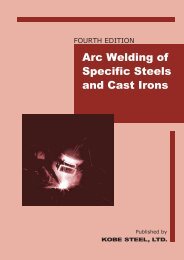
FOURTH EDITION<br />
<strong>Weld</strong> <strong>Imperfections</strong><br />
<strong>and</strong> <strong>Preventive</strong><br />
<strong>Measures</strong><br />
Published by
FOURTH EDITION<br />
<strong>Weld</strong> <strong>Imperfections</strong><br />
<strong>and</strong> <strong>Preventive</strong><br />
<strong>Measures</strong><br />
Kita-Shinagawa, Shinagawa-Ku, Tokyo, 141-8688 Japan
Published by KOBE STEEL, LTD.<br />
© 2011 by KOBE STEEL, LTD.<br />
5-912, Kita-Shinagawa, Shinagawa-Ku, Tokyo<br />
141-8688 Japan<br />
All rights reserved. No part of this book may be<br />
reproduced, in any form or by any means, without<br />
permission in writing from the publisher.<br />
The <strong>Weld</strong> <strong>Imperfections</strong> <strong>and</strong> <strong>Preventive</strong> <strong>Measures</strong> is<br />
to provide information to assist welding personnel<br />
study the arc welding technologies applied in steel<br />
fabrication.<br />
Reasonable care is taken in the compilation <strong>and</strong><br />
publication of this textbook to insure authenticity of<br />
the contents. No representation or warranty is made as<br />
to the accuracy or reliability of this information.
Introduction<br />
In the construction of such steel structures as buildings <strong>and</strong> bridges <strong>and</strong> the fabrication of<br />
such machinery as ships, autos, rolling stock, <strong>and</strong> pressure vessels, arc welding is<br />
indispensable method for joining metals. Therefore, the reliability of steel structures <strong>and</strong><br />
machinery depends on the quality of the welds as well as the quality of the steel materials. In<br />
order to produce satisfactory weldments which fulfill the requirements of quality, the integrity<br />
of quality control is very important. For integral quality control, all the personnel (including<br />
managers, engineers, inspectors, supervisors, foremen, welders, <strong>and</strong> welding operators) who<br />
are involved in arc welding should have adequate knowledge of weld imperfections <strong>and</strong><br />
preventive measures. The <strong>Weld</strong> <strong>Imperfections</strong> <strong>and</strong> <strong>Preventive</strong> <strong>Measures</strong> is prepared so as to<br />
outline weld imperfections, their causes, <strong>and</strong> preventive measures.<br />
This textbook contains essential information of surface irregularities <strong>and</strong> weld<br />
discontinuities. Surface irregularities can be defined as "any number of surface conditions that<br />
result in notches or abrupt changes in thickness or appearance." Surface irregularities include<br />
uneven weld ripples, excessive reinforcement, concave or convex fillet welds, uneven-leg fillet<br />
welds, undercut, overlap, herringbone, pockmarks, mouse footmarks, <strong>and</strong> underfill. <strong>Weld</strong><br />
discontinuities can be defined as "an interruption of the typical structure of a material, such<br />
as a lack of homogeneity in the mechanical, metallurgical or physical characteristics of the<br />
material or weldment. <strong>Weld</strong> discontinuities include porosity, slag inclusions, incomplete fusion,<br />
incomplete joint penetration, excessive melt-through, cold cracks, <strong>and</strong> hot cracks. However, a<br />
surface irregularity or weld discontinuity is not a rejectable defect when it is within the<br />
permissible range of extent according to the relevant specification.<br />
This textbook has been edited by employing as many photographs <strong>and</strong> drawings as possible<br />
in order to help the learners fully underst<strong>and</strong> specific technologies of arc welding <strong>and</strong> related<br />
weld imperfections. The information contained in this textbook includes those derived from<br />
the reference books listed below.<br />
References<br />
(1) Kobe Steel, Ltd., "<strong>Weld</strong>ing Electrode H<strong>and</strong>book," 1964<br />
(2) Japan <strong>Weld</strong>ing Engineering Society, "Typical <strong>Weld</strong> Photographs," 1967, Sanpo Publications Inc.<br />
(3) Japan Cultural <strong>and</strong> Industrial Promotion Co. Ltd., "Photographic <strong>Weld</strong>ing," 1961<br />
(4) Overseas Vocational Training Association, "Arc <strong>Weld</strong>ing," 1985<br />
(5) American <strong>Weld</strong>ing Society, "<strong>Weld</strong>ing H<strong>and</strong>book," 1987<br />
(6) American <strong>Weld</strong>ing Society, "Jefferson's <strong>Weld</strong>ing Encyclopedia," 18th Edition, 1997<br />
(7) American <strong>Weld</strong>ing Society, "<strong>Weld</strong> <strong>and</strong> Base Metal Discontinuities," 1986<br />
iii
Contents<br />
Surface irregularities 1<br />
Fig. 1 — Uneven weld ripples<br />
Fig. 2 — Excessive reinforcement<br />
Fig. 3 — Concave fillet weld, Convex fillet weld<br />
Fig. 4 — Uneven-leg fillet weld<br />
Fig. 5 — Undercut<br />
Fig. 6 — Overlap<br />
Fig. 7 — Herringbone, Pock mark, Mouse footmark<br />
Fig. 8 — Underfill (Internal concavity)<br />
<strong>Weld</strong> discontinuities 9<br />
Fig. 9 — Porosity (Pit)<br />
Fig. 10 — Porosity (Blowhole)<br />
Fig. 11 — Slag inclusions<br />
Fig. 12 — Incomplete fusion<br />
Fig. 13 — Incomplete joint penetration<br />
Fig. 14 — Excessive melt-through (Burn-through)<br />
Fig. 15 — Cold crack (Root crack, Toe crack, Underbead crack, Transverse crack)<br />
Fig. 16 — Cold crack (Lamellar tear)<br />
Fig. 17 — Hot crack (Crater crack, Longitudinal crack, Pear-shape crack, Sulfur crack)<br />
Appendix A 18<br />
Fig. A-1 Rupture in welds because of weld imperfections (Bend test)<br />
Fig. A-2 Rupture in welds because of weld imperfections (Tensile test)<br />
v
— Surface Irregularity —<br />
SMAW<br />
SAW<br />
Fig. 1 UNEVEN WELD RIPPLES<br />
Definition: Abrupt changes in the profiles of weld bead ripples<br />
Main Causes:<br />
(1) Too low or high welding amperage or voltage<br />
(2) Inappropriate electrode manipulation<br />
(irregular, too fast, or too slow)<br />
(3) Too much moisture in coatings or fluxes (SMAW, SAW)<br />
(4) Too much flux-burden height (SAW)<br />
<strong>Preventive</strong> <strong>Measures</strong>:<br />
(1) Use proper welding amperages <strong>and</strong> voltages.<br />
(2) Manipulate electrodes at appropriate speeds.<br />
(3) Redry coatings <strong>and</strong> fluxes.<br />
(4) Use a proper flux-burden height.<br />
1
— Surface Irregularity —<br />
SAW<br />
GTAW<br />
Narrow<br />
weaving<br />
Appropriate<br />
weaving width<br />
Wide<br />
weaving<br />
Fig. 2 EXCESSIVE REINFORCEMENT<br />
Definition: The face or root reinforcement that has a larger height<br />
than that specified<br />
Main Causes:<br />
(1) Too slow electrode manipulation<br />
(2) Too much root opening (root reinforcement)<br />
(3) Too much welding amperage (root reinforcement)<br />
<strong>Preventive</strong> <strong>Measures</strong>:<br />
(1) Manipulate electrodes at appropriate speeds.<br />
(2) Adjust root opening.<br />
(3) Use appropriate welding amperages.<br />
(4) Control the electrode displacement (see the above drawings).<br />
2
— Surface Irregularity —<br />
(A) Good fillet weld<br />
(B) Concave fillet weld<br />
(C) Convex fillet weld<br />
Fig. 3 CONCAVE FILLET WELD, CONVEX FILLET WELD<br />
Definition: A fillet weld that has excessive concavity or convexity<br />
Main Causes:<br />
(1) Too fast electrode manipulation, using too high<br />
welding amperage (Concave fillet weld)<br />
(2) Too low welding amperage or<br />
too slow electrode manipulation (Convex fillet weld)<br />
(3) Inappropriate electrode travel angle<br />
<strong>Preventive</strong> <strong>Measures</strong>:<br />
Use appropriate welding amperages <strong>and</strong> electrode manipulation speeds<br />
with an appropriate travel angle.<br />
3
— Surface Irregularity —<br />
(A) Uneven-leg fillet weld<br />
in horizontal position<br />
(B) Even-leg fillet weld<br />
in horizontal position<br />
Appropriate electrode work angle<br />
Fig. 4 UNEVEN-LEG FILLET WELD<br />
Definition: A fillet weld that has uneven legs<br />
(the upper leg is often smaller than the lower leg)<br />
Main Causes:<br />
Inappropriate electrode work angle<br />
<strong>Preventive</strong> <strong>Measures</strong>:<br />
Use an appropriate electrode work angle (see the above drawings).<br />
4
— Surface Irregularity —<br />
Horizontal fillet weld<br />
Flat-position groove weld<br />
Horizontal fillet weld<br />
Fig. 5 UNDERCUT<br />
Definition: A groove that is gouged in the base metal adjacent<br />
to the weld toe or weld root <strong>and</strong> is left unfilled by the weld metal<br />
Main Causes:<br />
(1) Too high welding amperage<br />
(2) Too fast electrode manipulation<br />
(3) Too long arc length, or too high arc voltage<br />
(4) Too large drag angle <strong>and</strong> work angle of electrode<br />
(5) The wire tracking is too close to the groove face (SAW)<br />
<strong>Preventive</strong> <strong>Measures</strong>:<br />
(1)-(4) Use appropriate welding amperages, electrode manipulation speeds,<br />
arc lengths (or arc voltages), <strong>and</strong> electrode drag angles.<br />
(5) Adjust the wire tracking location.<br />
5
— Surface Irregularity —<br />
Butt weld in horizontal vertical position<br />
Fillet weld in horizontal position<br />
Fig. 6 OVERLAP<br />
Definition: The protrusion of weld metal beyond the weld toe or weld root<br />
Main Causes:<br />
(1) Too low welding amperage<br />
(2) Too slow electrode manipulation<br />
(3) Too short arc length, or too low arc voltage<br />
(4) Too small travel angle <strong>and</strong> work angle of electrode<br />
<strong>Preventive</strong> <strong>Measures</strong>:<br />
Use appropriate welding amperages, manipulation speeds,<br />
arc lengths (arc voltages), <strong>and</strong> electrode positioning.<br />
6
— Surface Irregularity —<br />
Herringbone in SAW weld<br />
Pock mark in SAW weld<br />
Mouse footmark in SMAW weld<br />
Fig. 7 HERRINGBONE, POCK MARK, MOUSE FOOTMARK<br />
Definition: Shallow indentations on the surface of welds<br />
Main Causes:<br />
(1) Moisture in coatings or fluxes<br />
(2) Rust, paint, or moisture on the joint fusion faces<br />
<strong>Preventive</strong> <strong>Measures</strong>:<br />
(1) Redry the coatings <strong>and</strong> fluxes.<br />
(2) Remove rust, paint, <strong>and</strong> moisture from the joint fusion faces.<br />
7
— Surface Irregularity —<br />
SMAW<br />
Top<br />
5G Pipe<br />
Bottom<br />
(C)<br />
(B)<br />
(A)<br />
Wide weaving Appropriate weaving width Narrow weaving<br />
Fig. 8 UNDERFILL (INTERNAL CONCAVITY)<br />
Definition: A depression on the weld face or root surface<br />
extending below the adjacent surface of the base metal<br />
Main Causes:<br />
(1) Too small root opening, groove angle, or too much root face<br />
(2) Too low amperage, or too long arc<br />
(3) Inappropriate electrode manipulation<br />
<strong>Preventive</strong> <strong>Measures</strong>:<br />
(1) Adjust the root opening, groove angle, <strong>and</strong> root face.<br />
(2) Use appropriate welding amperages <strong>and</strong> keep the arc length short.<br />
(3) Use the suitable electrode manipulation as shown in the above drawings.<br />
8
— <strong>Weld</strong> Discontinuities —<br />
SMAW<br />
GMAW<br />
SAW<br />
Fig. 9 POROSITY (PIT)<br />
Definition: Cavity type discontinuities formed by gas entrapment during solidification<br />
Main Causes:<br />
(1) Rust, oil, paint, or moisture on the joint fusion faces <strong>and</strong><br />
high sulfur content of the base metal<br />
(2) Moisture in coatings, fluxes, or shielding gases<br />
(3) Too little shielding gas (GMAW) or flux-burden height (SAW)<br />
(4) Too strong wind<br />
(5) Too much welding amperage, arc length, or arc voltage<br />
<strong>Preventive</strong> <strong>Measures</strong>:<br />
(1) Clean the joint fusion faces.<br />
(2) Redry coatings <strong>and</strong> fluxes <strong>and</strong> use suitable shielding gases.<br />
(3) Use proper amounts of shielding gas <strong>and</strong> flux-burden height.<br />
(4) Use a wind screen.<br />
(5) Use appropriate welding amperages, arc lengths, <strong>and</strong> arc voltages.<br />
9
— <strong>Weld</strong> Discontinuities —<br />
X-Ray Test<br />
Fracture Test<br />
Fig. 10 POROSITY (BLOWHOLE)<br />
Definition: Cavity type discontinuities formed by gas entrapment during solidification<br />
Main Causes:<br />
(1) Rust, oil, paint, or moisture on the joint fusion faces <strong>and</strong><br />
high sulfur content of the base metal<br />
(2) Moisture in coatings, fluxes, or shielding gases<br />
(3) Too little shielding gas (GMAW) or flux-burden height (SAW)<br />
(4) Too strong wind<br />
(5) Too much welding amperage, arc length, or arc voltage<br />
<strong>Preventive</strong> <strong>Measures</strong>:<br />
(1) Clean the joint fusion faces.<br />
(2) Redry coatings <strong>and</strong> fluxes <strong>and</strong> use suitable shielding gases.<br />
(3) Use proper amounts of shielding gas <strong>and</strong> flux-burden height.<br />
(4) Use a wind screen.<br />
(5) Use appropriate welding amperages, arc lengths, <strong>and</strong> arc voltages.<br />
10
— <strong>Weld</strong> Discontinuities —<br />
X-Ray Test<br />
Fig. 11 SLAG INCLUSIONS<br />
Definition: Nonmetallic solid materials entrapped in weld metals<br />
or between weld metal <strong>and</strong> base metal<br />
Main Causes:<br />
(1) Too low welding amperage<br />
(2) Too much arc length<br />
(3) Too much weaving width<br />
(4) Too narrow groove<br />
(5) Slag remaining on the preceding layer<br />
(6) Inclined weld axis downward to the welding direction in the flat position<br />
<strong>Preventive</strong> <strong>Measures</strong>:<br />
(1)-(4) Use appropriate welding parameters <strong>and</strong> groove angles.<br />
(5) Remove slag of the preceding layer completely.<br />
(6) Keep the weld axis in horizontal by positioning.<br />
11
— <strong>Weld</strong> Discontinuities —<br />
X-Ray Test<br />
Fig. 12 INCOMPLETE FUSION<br />
Definition: A weld discontinuity in which fusion did not occur<br />
between weld metal <strong>and</strong> joint fusion face or between adjoining weld beads.<br />
Main Causes:<br />
(1) Too low welding amperage<br />
(2) Too fast or slow electrode manipulation<br />
(3) Too much or too little arc length or arc voltage<br />
(4) Too narrow welding groove<br />
<strong>Preventive</strong> <strong>Measures</strong>:<br />
Use appropriate welding parameters <strong>and</strong> groove angles.<br />
12
— <strong>Weld</strong> Discontinuities —<br />
X-ray test<br />
Fig. 13 INCOMPLETE JOINT PENETRATION<br />
Definition: Joint penetration that is unintentionally less than<br />
the thickness of the weld joint<br />
Main Causes:<br />
(1) Too narrow welding groove<br />
(2) Too low welding amperage<br />
(3) Too much arc length or arc voltage<br />
(4) Too fast or too slow electrode manipulation<br />
<strong>Preventive</strong> <strong>Measures</strong>:<br />
(1) Use appropriate groove design.<br />
(2)-(4) Use appropriate welding amperages, arc lengths (or arc voltages),<br />
<strong>and</strong> electrode manipulation.<br />
13
— <strong>Weld</strong> Discontinuities —<br />
Fig. 14 EXCESSIVE MELT-THROUGH (BURN-THROUGH)<br />
Definition: A hole through the weld metal, usually occurring in the first pass<br />
Main Causes:<br />
(1) Too much root opening<br />
(2) Too high welding amperage<br />
<strong>Preventive</strong> <strong>Measures</strong>:<br />
Use appropriate root openings <strong>and</strong> welding amperages.<br />
14
— <strong>Weld</strong> Discontinuities —<br />
Root crack<br />
Toe crack<br />
Underbead crack<br />
Transverse crack<br />
X-Ray Test<br />
Fig. 15 COLD CRACK (ROOT CRACK, TOE CRACK,<br />
UNDERBEAD CRACK, TRANSVERSE CRACK)<br />
Definition: A crack which develops after solidification is completed<br />
at temperatures lower than approx. 200°C for steel<br />
Main Causes:<br />
(1) Diffusible hydrogen in welds<br />
(2) Brittle structure of weld<br />
(3) Restraint stresses in welds<br />
<strong>Preventive</strong> <strong>Measures</strong>:<br />
(1) Redry coatings <strong>and</strong> fluxes.<br />
(2) Preheat base metals.<br />
15
— <strong>Weld</strong> Discontinuities —<br />
Fig. 16 COLD CRACK (LAMELLAR TEAR)<br />
Definition: A subsurface terrace <strong>and</strong> step-like fracture in the base metal with<br />
a basic orientation parallel to the wrought surface<br />
Main Causes:<br />
(1) Inadequate ductility of the base metal in the thickness direction<br />
(2) High sulfur content of the base metal<br />
(3) Nonmetallic inclusions in the base metal<br />
(4) Hydrogen in the weld<br />
(5) Tensile stresses in the thickness direction of the base metal<br />
<strong>Preventive</strong> <strong>Measures</strong>:<br />
(1)-(3) Use a base metal which has higher ductility in the<br />
thickness direction, low sulfur, <strong>and</strong> low inclusions.<br />
(4) Use low hydrogen type electrodes.<br />
(5) Modify the joint details <strong>and</strong> the welding procedures to decrease<br />
the stresses.<br />
16
— <strong>Weld</strong> Discontinuities —<br />
Crater crack in SMAW<br />
Pear-shape crack in SAW<br />
Longitudinal crack in SMAW<br />
Sulfur crack in SMAW<br />
Fig. 17 HOT CRACK (CRATER CRACK, LONGITUDINAL CRACK,<br />
PEAR-SHAPE CRACK, SULFUR CRACK )<br />
Definition: A crack that develops during solidification<br />
Main Causes:<br />
(1) Too high welding amperage<br />
(2) Too narrow welding groove<br />
(3) Much sulfur content of the base metal<br />
<strong>Preventive</strong> <strong>Measures</strong>:<br />
(1) Use proper welding amperages <strong>and</strong> crater treatment.<br />
(2) Use an appropriate groove angle.<br />
(3) Inspect the sulfur segregation of the welding groove before welding.<br />
17
— Appendix A —<br />
Fracture in welds<br />
Rejected<br />
Accepted<br />
Fig. A-1 Fracture in welds because of weld imperfections (Bend test)<br />
18
— Appendix A —<br />
Fracture in welds<br />
Fracture in base metal<br />
Fig. A-2 Fracture in welds because of weld imperfections (Tension test)<br />
19