PSI Certified Stationary Engine Fuel System - Kohler Power
PSI Certified Stationary Engine Fuel System - Kohler Power
PSI Certified Stationary Engine Fuel System - Kohler Power

You also want an ePaper? Increase the reach of your titles
YUMPU automatically turns print PDFs into web optimized ePapers that Google loves.
<strong>PSI</strong>CERTSTAT-B<br />
2009 Emission <strong>Certified</strong><br />
<strong>Stationary</strong> <strong>Engine</strong> <strong>Fuel</strong> and<br />
Control <strong>System</strong> Diagnostic<br />
Service Manual<br />
TP-6724 01/10A
<strong>PSI</strong>CERTSTAT-B<br />
Table of Contents<br />
General Information ................................................................................................ 3<br />
An overview of this Service Manual<br />
Maintenance ............................................................................................................ 6<br />
General maintenance and maintenance interval information<br />
<strong>Fuel</strong> <strong>System</strong> .......................................................................................................... 14<br />
An overview of the fuel system and its components<br />
LPG <strong>Fuel</strong> <strong>System</strong> Diagnosis ................................................................................ 21<br />
How to identify a general problem<br />
LPG Symptom Diagnostics .................................................................................. 29<br />
How to correct a specific problem<br />
Electrical Section .................................................................................................... 42<br />
Diagnostic Scan Tool ........................................................................................ 61<br />
Using the DST for testing and trouble shooting<br />
<strong>Engine</strong> Wire Harness Repair ............................................................................ 83<br />
Repairing a wire harness on the vehicle<br />
Diagnostic Trouble Codes (DTCs) ................................................................. 87<br />
Application, schematic and DTC specific code information<br />
Definitions ............................................................................................................. 267<br />
Definitions of phrases and acronyms used throughout this Service Manual
General Information<br />
3
GENERAL INFORMATION<br />
INTRODUCTION<br />
This service manual has been developed to provide<br />
the service technician with the basic<br />
understanding of the <strong>PSI</strong> certified fuel and emission<br />
systems for their GM engine line. This<br />
manual should be used in conjunction with the<br />
base engine manual and the OEM service manual<br />
when diagnosing fuel or electrical problems.<br />
SERVICING YOUR EMISSIONS<br />
CERTIFIED ENGINE<br />
Any maintenance and repair should be performed<br />
by trained and experienced service technicians.<br />
Proper tools and equipment should be used to<br />
prevent injury to the servicing technician and<br />
damage to the vehicle or components. Service repairs<br />
should always be performed in a safe<br />
environment and the technician should always<br />
wear protective clothing to prevent injury.<br />
FUEL QUALITY<br />
<strong>PSI</strong> NG engine are designed to operate on pipeline<br />
quality natural gas with a heat value of 1050<br />
BTU or higher. LPG engines and fuel systems are<br />
designed to operate on HD-5 or HD-10 specification<br />
LPG fuel. <strong>Fuel</strong> other than HD-5 or HD-10 may<br />
cause harm to the engine’s emission control system<br />
and a warranty claim may be denied on this<br />
basis if operators can readily find the proper fuel.<br />
Use of any other fuel may result in your engine no<br />
longer operating in compliance with CARB or EPA<br />
emissions requirements.<br />
FUEL SYSTEM CAUTIONS<br />
Do not smoke, carry lighted tobacco or<br />
use a lighted flame of any type when<br />
working on or near any fuel related<br />
component. Highly flammable air-fuel<br />
mixtures may be present and can be<br />
ignited causing personal injury<br />
Do not allow LPG to contact the skin.<br />
LPG is stored in the fuel tank as a liquid.<br />
When LPG contacts the<br />
atmosphere, it immediately expands<br />
into a gas, resulting in a refrigeration<br />
effect that can cause severe burns to<br />
the skin.<br />
Do not allow LPG to accumulate in<br />
areas below ground level such as in a<br />
service pit or underground ventilation<br />
systems. LPG is heavier than air and<br />
can displace oxygen, creating a dangerous<br />
condition<br />
Do not make repairs to the LPG fuel<br />
system if you are not familiar with or<br />
trained to service LPG fuel system.<br />
Contact the dealer who sold you the<br />
vehicle to locate a repair facility with<br />
trained technicians to repair your fuel<br />
system<br />
WARNINGS, CAUTIONS AND NOTES<br />
This manual contains several different Warnings,<br />
Cautions, and Notes that must be observed to<br />
prevent personal injury and or damage to the vehicle,<br />
the fuel system or personal property.<br />
A “WARNING“ is an advisement that by performing<br />
a process or procedure listed in this manual<br />
improperly may result in serious bodily injury,<br />
death and/or serious damage to the vehicle or<br />
property.<br />
4
GENERAL INFORMATION<br />
PROPER USE OF THIS SERVICE MANUAL,<br />
TOOLS AND EQUIPMENT<br />
To reduce the potential for injury to the technician<br />
or others and to reduce damage to the equipment<br />
during service repairs the technician should observe<br />
the following steps:<br />
<br />
The service procedures defined in this manual,<br />
when followed, have been found to be a safe<br />
and efficient process to repair the fuel system.<br />
In some cases special tools may be required to<br />
perform the necessary procedures to safely<br />
remove and replace a failed component.<br />
Always leak check any fuel system<br />
connection after servicing! Use an<br />
electronic leak detector and/or a liquid<br />
leak detection solution. Failure to leak<br />
check could result in serious bodily<br />
injury, death, or serious property damage.<br />
<br />
<br />
<br />
The installed <strong>PSI</strong> fuel system has been certified<br />
with the Environmental Protection Agency<br />
(EPA) and complies with the regulation in effect<br />
at the time of certification. When servicing<br />
the fuel and emission control system you<br />
should follow all the recommended service and<br />
repair procedures to insure the fuel and emissions<br />
system is operating as designed and<br />
certified. Purposely or knowingly defeating or<br />
disabling any part or the fuel and emission system<br />
may be in violation of the anti-tampering<br />
provision of the EPA’s Clean Air Act.<br />
Tools identified in this manual with the prefix<br />
“J” or “BT” can be procured through SPX in<br />
Warren, Michigan.<br />
Other special tools identified in this manual<br />
can be acquired through the equipment OEM<br />
or <strong>PSI</strong>.<br />
IMPORTANT<br />
It is important to remember that there may be a<br />
combination of Metric and Imperial fasteners used<br />
in the installation of the <strong>PSI</strong> fuel system. Check to<br />
insure proper fit when using a socket or wrench on<br />
any fastener to prevent damage to the component<br />
being removed or injury from “slipping off” the fastener.<br />
5
Maintenance<br />
6
MAINTENANCE<br />
The maintenance of an engine and related components<br />
are critical to its operating performance<br />
and lifespan. Industrial engines operate in environments<br />
that often include hot and cold<br />
temperatures and extreme dust. The recommended<br />
maintenance schedule is listed in this<br />
section, however, environmental operating conditions<br />
and additional installed equipment may<br />
require more frequent inspection and servicing.<br />
The owner and/or service agent should review the<br />
operating conditions of the equipment to determine<br />
the inspection and maintenance intervals.<br />
When performing maintenance on the engine,<br />
turn the ignition OFF and disconnect the battery<br />
negative cable to avoid injury or damage<br />
to the engine.<br />
The engine installed in this equipment uses a<br />
drive belt that drives the water pump, alternator<br />
and additional pumps or devices. It is important to<br />
note that the drive belt is an integral part of the<br />
cooling and charging system and should be inspected<br />
according to the maintenance schedule in<br />
this section. When inspecting the belts check for:<br />
<br />
<br />
<br />
<br />
<br />
Cracks<br />
Chunking of the belt<br />
Splits<br />
Material hanging loose from the belt<br />
Glazing, hardening<br />
If any of these conditions exist the belt should be<br />
replaced with the recommended OEM replacement<br />
belt.<br />
agents” on belts is not recommended.<br />
COOLING SYSTEM<br />
It is important that the cooling system of the engine<br />
be maintained properly to ensure proper<br />
performance and longevity.<br />
Do not remove the cooling system pressure<br />
cap (radiator cap) when the engine is hot.<br />
Allow the engine to cool and then remove the<br />
cap slowly to allow pressure to vent. Hot<br />
coolant under pressure may discharge violently.<br />
Note that there may be an LPG vaporizer connected<br />
to the cooling system and the fuel system<br />
may be adversely affected by low coolant levels<br />
and restricted or plugged radiator cores. Therefore,<br />
the cooling system must be maintained<br />
according to the recommend maintenance schedule<br />
in this section and also include:<br />
<br />
<br />
<br />
<br />
The regular removal of dust, dirt and debris<br />
from the radiator core and fan shroud.<br />
Inspection of coolant hoses and components<br />
for leaks, especially at the radiator hose connections.<br />
Tighten hose clamps if necessary.<br />
Check radiator hoses for swelling, separation,<br />
hardening, cracks or any type of deterioration.<br />
If any of these conditions exist the hose<br />
should be replaced with a recommended OEM<br />
replacement part.<br />
Inspect the radiator cap to ensure proper sealing.<br />
SERPENTINE BELT SYSTEM<br />
Serpentine belts utilize a spring-loaded tensioner<br />
to keep the belt properly adjusted. Serpentine<br />
belts should be checked according to the maintenance<br />
schedule in this section.<br />
IMPORTANT:<br />
The use of “belt dressing” or “anti-slipping<br />
7
COOLANT<br />
The engine manufacturer recommends the cooling<br />
system be filled with a 50/50 mixture of antifreeze<br />
and water. The use of DexCool “Long Life” type<br />
coolant is required. This antifreeze is typically a<br />
bright orange in color and should meet the requirements<br />
issued by <strong>PSI</strong>. Coolant should have a<br />
minimum boiling point of 300F (149c) and a freezing<br />
point no higher than -34F (-37c).<br />
Do not add plain water. Replace coolant per the<br />
recommended schedule.<br />
IMPORTANT:<br />
The manufacturers of the engine and fuel system<br />
do not recommend the use of “stop leak” additives<br />
to repair leaks in the cooling system. If leaks are<br />
present the radiator should be removed and repaired<br />
or replaced.<br />
ENGINE ELECTRICAL SYSTEM MAINTNANCE<br />
The engine’s electrical system incorporates an<br />
electronic control module (ECM) to control various<br />
related components. The electrical system connections<br />
and ground circuits require good<br />
connections. Follow the recommended maintenance<br />
schedule in this section to maintain optimum<br />
performance. When inspecting the electrical system<br />
check the following:<br />
<br />
<br />
<br />
<br />
<br />
<br />
<br />
<br />
<br />
Check Positive and Negative cables for corrosion,<br />
rubbing, chafing, burning and to ensure<br />
tight connections at both ends.<br />
Check battery for cracks or damage to the<br />
case and replace if necessary.<br />
Inspect engine wire harness for rubbing, chafing,<br />
pinching, burning, and cracks or breaks in<br />
the wiring.<br />
Verify that engine harness connectors are correctly<br />
locked in by pushing in and then pulling<br />
the connector halves outward.<br />
Inspect ignition coil wire for hardening, cracking,<br />
arcing, chafing, burning, separation, split<br />
boot covers.<br />
Check spark plug wires for hardening, cracking,<br />
chafing, arcing or burning, separation, and<br />
split boot covers.<br />
Replace spark plugs at the required intervals<br />
per the recommended maintenance schedule.<br />
Verify that all electrical components are securely<br />
mounted to the engine or chassis.<br />
Verify that any additional electrical services<br />
<br />
8<br />
installed by the owner are properly installed in<br />
the system.<br />
Verify that the MIL, charging, and oil pressure<br />
lights illuminate momentarily during engine start.<br />
ENGINE CRANKCASE OIL<br />
OIL RECOMMENDATION<br />
To achieve proper engine performance and durability,<br />
it is important that you only use engine<br />
lubricating oils displaying the American Petroleum<br />
Institute (API) “Starburst” Certification Mark<br />
‘FOR GASOLINE ENGINES’ on the container.<br />
Gasoline engines that are converted to run on<br />
LPG or NG fuels must use oils labeled for gasoline<br />
engines. Oils specifically formulated for<br />
Heavy Duty or Natural Gas <strong>Engine</strong>s are not acceptable<br />
IMPORTANT:<br />
Oils recommended by the engine manufacturer<br />
already contain a balanced additive treatment.<br />
Oils containing “solid” additives, non-detergent<br />
oils, or low quality oils are not recommended by<br />
the engine manufacturer. Supplemental additives<br />
added to the engine oil are not necessary and<br />
may be harmful. The engine and fuel system<br />
supplier do not review, approve or recommend<br />
such products.<br />
SYNTHETIC OILS<br />
Synthetic oils have been available for use in industrial<br />
engines for a relatively long period of<br />
time and may offer advantages in cold and hot<br />
temperatures. However, it is not known if synthetic<br />
oils provide operational or economic<br />
bene-based oils<br />
in industrial engines. Use of synthetic oils does<br />
not permit the extension of oil change intervals.<br />
CHECKING/FILLING ENGINE OIL LEVEL<br />
IMPORTANT:<br />
Care must be taken when checking engine oil level.<br />
Oil level must be maintained between the<br />
“ADD” mark and the “FULL” mark on the dipstick.<br />
To ensure that you are not getting a false reading,<br />
make sure the following steps are taken before
checking the oil level.<br />
1. Stop engine.<br />
2. Allow approximately several minutes for the oil<br />
to drain back into the oil pan.<br />
3. Remove the dipstick. Wipe with a clean cloth<br />
or paper towel and reinstall. Push the dipstick<br />
all the way into the dipstick tube.<br />
4. Remove the dipstick and note the amount of<br />
oil on the dipstick. The oil level must be between<br />
the “FULL” and “ADD” marks.<br />
Figure 2 <strong>Engine</strong> Oil Dip tick (Typical)<br />
5. If the oil level is below the “ADD” mark reinstall<br />
the dipstick into the dipstick tube and proceed<br />
to Step 6.<br />
6. Remove the oil <br />
7. Add the required amount of oil to bring the<br />
level up to, but not over, the “FULL” mark on<br />
the dipstick Reinstall the oil <br />
valve rocker arm cover and wipe any excess<br />
oil clean.<br />
IMPORTANT:<br />
Change oil when engine is warm and the old oil<br />
flows more freely.<br />
2. Stop engine<br />
IMPORTANT:<br />
<strong>Engine</strong> oil will be hot. Use protective gloves to<br />
prevent burns. <strong>Engine</strong> oil contains chemicals<br />
which may be harmful to your health. Avoid skin<br />
contact.<br />
3. Remove drain plug and allow the oil to drain.<br />
4. Remove and discard oil ling<br />
ring.<br />
5. Coat sealing ring on the new <br />
engine oil, wipe the sealing surface on the<br />
emove any dust, dirt<br />
or debris. Tighten <br />
manufacturers instructions). Do not over tighten.<br />
6. Check sealing ring on drain plug for any damage,<br />
replace if necessary, wipe plug with clean<br />
rag, wipe pan sealing surface with clean rag<br />
and re-install plug into the pan. Tighten to<br />
speci<br />
7. Fill crankcase with oil.<br />
8. Start engine and check for oil leaks.<br />
9. Dispose of oil and nner.<br />
CHANGING THE ENGINE OIL<br />
IMPORTANT:<br />
When changing the oil, always change the oil<br />
<br />
1. Start the engine and run until it reaches normal<br />
operating temperature.<br />
An overfilled crankcase (oil level being too<br />
high) can cause an oil leak, a fluctuation or<br />
drop in oil pressure. When overfilled, the engine<br />
crankshafts splash and agitate the oil,<br />
causing it to aerate or foam.<br />
9
FUEL SYSTEM INSPECTION AND<br />
MAINTENANCE<br />
LPG FUEL SYSTEM<br />
The fuel system installed on this industrial engine<br />
has been designed to meet the stationary engine<br />
emission standard applicable for the 2009 and<br />
later model years. To ensure compliance to these<br />
standards, follow the recommended maintenance<br />
schedule contained in this section.<br />
INSPECTION AND MAINTENANCE OF THE<br />
FUEL STORAGE CYLINDER<br />
The fuel storage cylinder should be inspected<br />
daily or at the beginning of each operational shift<br />
for any leaks, external damage, adequate fuel<br />
supply and to ensure the manual service valve is<br />
open. <strong>Fuel</strong> storage cylinders should always be<br />
securely mounted, inspect the securing straps or<br />
retaining devices for damage ensure that all locking<br />
devices are closed and locked. Check to<br />
ensure that the fuel storage cylinder is positioned<br />
with the locating pin in the tank collar on all horizontally<br />
mounted cylinders this will ensure the<br />
proper function of the cylinder relief valve.<br />
When refueling or exchanging the fuel cylinder,<br />
check the quick mage. Also<br />
verify O-ring is in place and inspect for cracks,<br />
chunking or separation. If damage to the o-ring<br />
is found, replace prior to rvice<br />
line quick coupler for any thread damage.<br />
IMPORTANT:<br />
When refueling the fuel cylinder, wipe both the<br />
female and male connection with a clean rag prior<br />
to event dust, dirt and debris from being<br />
introduced to the fuel cylinder.<br />
<br />
<br />
Check to make sure ecurely mounted.<br />
Check xternal damage or<br />
distortion. If damaged replace fuel <br />
REPLACING THE FUEL FILTER:<br />
1. Move the equipment to a well ventilated area<br />
and verify that sparks, ignition and any heat<br />
sources are not present.<br />
2. Start the engine.<br />
3. If the engine operates on a positive pressure<br />
fuel system, run the engine with the fuel<br />
supply closed to remove fuel from the system.<br />
IMPORTANT:<br />
A small amount of fuel may still be present in<br />
the fuel line. Use gloves and proper eye protection<br />
to prevent burns. If liquid fuel<br />
continues to <br />
removed, make sure the manual valve is fully<br />
closed.<br />
4. Slowly loosen the inlet nnect.<br />
5. Slowly loosen the outlet sconnect.<br />
6. Remove the sing form the equipment.<br />
7. Check for contamination.<br />
8. Tap the opening of the <br />
9. Check for debris.<br />
10. Check canister for proper mounting direction.<br />
11. Reinstall the pment.<br />
12. Tighten the inlet and outlet ication.<br />
13. Check for leaks at the inlet and outlet<br />
ction<br />
using a soapy solution or an electronic<br />
leak detector, if leaks are detected make<br />
repairs<br />
INSPECTION AND REPLACEMENT OF THE<br />
FUEL FILTER<br />
The fuel system on this emission certi<br />
may utilize an in-line replaceable fuel ement.<br />
This element should be replaced, at the<br />
intervals specinance<br />
schedule. When inspecting the fuel <br />
check the following:<br />
<br />
Check for leaks at the inlet and outlet <br />
using a soapy solution or an electronic leak<br />
detector and repair if necessary.<br />
10
INTERGRATED ELECTRONIC PRESSURE<br />
REGULATOR (IEPR) MAINTENANCE AND<br />
INSPECTION<br />
IMPORTANT:<br />
The Integrated Electronic Pressure Regulator<br />
(IEPR) components have been speciesigned<br />
and calibrated to meet the fuel system<br />
requirements of the emission certi<br />
If the IEPR fails to operate or develops a leak, it<br />
should be repaired or replaced with the OEM<br />
recommended replacement parts. When inspecting<br />
the system check for the following items:<br />
<br />
<br />
<br />
<br />
<br />
<br />
Check for any fuel leaks at the inlet and outlet<br />
<br />
Check for any fuel leaks in the IEPR body.<br />
Check the inlet and outlet olant<br />
supply lines for water leaks if applicable.<br />
Check to ensure the IEPR is securely<br />
mounted and the mounting bolts are tight.<br />
Check IEPR for external damage.<br />
Check IEPR electrical connection to ensure<br />
the connector is seated and locked.<br />
CHECKING/DRAINING OIL BUILD-UP IN THE<br />
VAPORIZER REGULATOR<br />
During the course of normal operation for LPG<br />
engines oil or “heavy ends” may build inside the<br />
secondary chamber of the Vaporizer Regulator.<br />
These oil and heavy ends may be a result of poor<br />
fuel quality, contamination of the fuel, or regional<br />
variation of the fuel make up. A significant build<br />
up of oil can affect the performance of the secondary<br />
diaphragm response. The Recommended<br />
Maintenance Schedule found in this section recommends<br />
that the oil be drained periodically.<br />
This is the minimum requirement to maintain the<br />
emission warranty. More frequent draining of the<br />
Vaporizer Regulator is recommended where substandard<br />
fuel may be a problem. <strong>PSI</strong> recommends<br />
the Vaporizer Regulator be drained at every engine<br />
oil change if contaminated or substandard<br />
fuel is suspected or known to be have been used<br />
or in use with the emission complaint fuel system.<br />
This is known as special maintenance, and failure<br />
to follow this recommendation may be used to deny<br />
a warranty claim.<br />
IMPORTANT:<br />
Draining the regulator when the engine is warm<br />
11<br />
will help the oils to <br />
To drain the regulator, follow the steps below:<br />
1. Move the equipment to a well ventilated area<br />
and ensure no external ignition sources are<br />
present.<br />
2. Start the engine.<br />
3. With the engine running close the manual<br />
valve.<br />
4. When the engine runs out of fuel turn OFF the<br />
key when the engine stops and disconnect the<br />
negative battery cable.<br />
IMPORTANT:<br />
A small amount of fuel may still be present in the<br />
fuel line, use gloves to prevent burns, wear proper<br />
eye protection. If liquid fuels continues to <br />
from the connections when loosened check to<br />
make sure the manual valve is fully closed.<br />
5. Loosen the hose clamp at the inlet and outlet<br />
hoses and remove the hoses.<br />
6. Remove the regualtor mounting bolts.<br />
7. Place a small receptacle in the engine compartment.<br />
8. Rotate the regulator to 90° so that the outlet<br />
ptacle and<br />
drain the regulator.<br />
9. Inspect the secondary chamber for any large<br />
dried particles and remove.<br />
10. Remove the receptacle and reinstall the regulator<br />
retaining bolts and tighten to<br />
speci<br />
11. Reinstall the fuel hoses..<br />
12. Reconnect any other hoses removed during<br />
this procedure.<br />
13. Slowly open the manual service valve.<br />
IMPORTANT:<br />
The fuel cylinder manual valve contains an<br />
“Excess Flow Check Valve” open the manual<br />
valve slowly to prevent activating the “Excess<br />
Flow Check Valve.”<br />
14. Check for leaks at the inlet and outlet <br />
using a soapy solution or an electronic leak<br />
detector. If leaks are detected make repairs.<br />
Check coolant line connections to ensure no<br />
leaks are present.<br />
15. Start engine recheck for leaks at the regulator.<br />
16. Dispose of any drained material in safe and<br />
proper manner.
AIR FUEL MIXER/THROTTLE CONTROL<br />
DEVICE MAINTENANCE AND INSPECTION<br />
IMPORTANT:<br />
The Air <strong>Fuel</strong> Mixer components have been<br />
specically designed and calibrated to meet the<br />
fuel system requirements of the emission certi<br />
engine. The mixer should not be disassembled or<br />
rebuilt. If the mixer fails to operate or develops a<br />
leak the mixer should be replaced with the OEM<br />
recommended replacement parts.<br />
When inspecting the mixer check for the following<br />
items:<br />
<br />
<br />
<br />
<br />
<br />
<br />
<br />
Leaks at the inlet <br />
<strong>Fuel</strong> inlet hose for cracking, splitting or chaffing,<br />
replace if any of these condition exist.<br />
Ensure the mixer is securely mounted and is<br />
not leaking vacuum at the mounting gasket or<br />
surface.<br />
Inspect air inlet hose connection and clamp.<br />
Also inspect inlet hose for cracking, splitting or<br />
chafing. Replace if any of these conditions exist.<br />
Inspect Air cleaner element according to the<br />
Recommended Maintenance Schedule found<br />
in this section.<br />
Check <strong>Fuel</strong> lines for cracking, splitting or chafing.<br />
Replace if any of these conditions exist.<br />
Check for leaks at the throttle body and intake<br />
manifold.<br />
The HEGO sensor is sensitive to silicone based<br />
products. Do not use silicone sprays or hoses<br />
which are assembled using silicone lubricants.<br />
Silicone contamination can cause severe damage<br />
to the HEGO.<br />
When inspecting the Exhaust system check the<br />
following:<br />
<br />
<br />
<br />
<br />
<br />
<br />
Exhaust manifold at the cylinder head for<br />
leaks and that all retaining bolts and shields (if<br />
used) are in place.<br />
Manifold to exhaust pipe fasteners to ensure<br />
they are tight and that there are no exhaust<br />
leaks repair if necessary.<br />
HEGO electrical connector to ensure connector<br />
is seated and locked, check wires to<br />
ensure there is no cracking, splits chafing or<br />
“burn through.” Repair if necessary.<br />
Exhaust pipe extension connector for leaks<br />
tighten if necessary<br />
If the egine is equipped with a catalytic converter<br />
inspect the converter to ensure it is<br />
securely mounted.<br />
Check for any leaks at the inlet and outlet of<br />
the converter.<br />
EXHAUST SYSTEM AND CATALYTIC<br />
CONVERTER INSPECTION AND<br />
MAINTENANCE<br />
IMPORTANT:<br />
The exhaust system on this emission certingine<br />
contains a Heated Exhaust Gas Oxygen<br />
Sensor (HEGO) which provides feed back to the<br />
ECM on the amount of oxygen present in the exhaust<br />
stream after combustion.<br />
The oxygen in the exhaust stream is measured in<br />
voltage and sent to the ECM. The ECM then<br />
makes corrections to the fuel air ratio to ensure<br />
the proper fuel charge and optimum catalytic performance.<br />
Therefore, it is important that the<br />
exhaust connections remain secured and air tight.<br />
IMPORTANT:<br />
12
CERTIFIED STATIONARY ENGINE MAINTENANCE REQUIREMENTS<br />
Perform the following maintenance on the engine at the hours indicated and at equivalent hour intervals thereafter.<br />
Interval Hours<br />
Daily 1000 1500 2000 2500 3000 3500 4000 4500 5000<br />
General Maintenance Section<br />
Visual check for fluid leaks<br />
X<br />
Check engine oil level<br />
X<br />
Check coolant level<br />
X<br />
Change engine oil and filter<br />
Check LPG system for leaks<br />
Every 150 hours or 120 days of operation<br />
Prior to any service or maintenance activity<br />
Inspect accessory drive belts for cracks, breaks, splits or glazing X X X X X<br />
Inspect electrical system wiring for cuts, abrasions or corrosion X X<br />
Inspect all vacuum lines and fittings for cracks, breaks or hardening X X<br />
<strong>Engine</strong> Coolant Section<br />
Clean debris from radiator core<br />
Every 100 hours or 60 days of operation<br />
Change coolant X X X X X<br />
Inspect coolant hoses for cracks, swelling or deterioration X X X X X<br />
<strong>Engine</strong> Ignition <strong>System</strong> X X X X X<br />
Replace spark plugs X X<br />
Clean secondary ignition coil tower X X X X X<br />
Check spark plug wires for cuts abrasions or hardening<br />
X<br />
Replace distributor cap and rotor X X<br />
Replace spark plug wires X X<br />
<strong>Fuel</strong> <strong>System</strong> Maintenance<br />
Inspect air cleaner<br />
Replace filter element<br />
Every 200 hours, or every 100 hours in dusty environment<br />
Annually, or as required in dusty environments<br />
Replace fuel filter X X X X X<br />
Inspect Shut-off Valve for leaks and closing X X<br />
Leak check fuel lines X X<br />
Check air induction for leaks X X X X X<br />
Check manifold for vacuum leaks X X X X X<br />
Drain Vaporizer oil build up<br />
<strong>Engine</strong> Exhaust <strong>System</strong><br />
Inspect exhaust manifold for leaks X<br />
Every 2500 hrs<br />
X<br />
Inspect exhaust piping for leaks X X<br />
Check HEGO sensor(s) connector and wires for burns, cuts or damage X X<br />
Inspect catalyst for mechanical damage X X<br />
This maintenance schedule represents the manufacturer’s recommended maintenance intervals to maintain proper<br />
engine function.<br />
13
<strong>Fuel</strong> <strong>System</strong><br />
14
STATIONARY ENGINE FUEL SYSTEM SCHEMATIC<br />
15
DESCRIPTION AND OPERATION OF THE FUEL<br />
SYSTEMS<br />
NG & LP VAPOR FUEL SYSTEM<br />
The primary components of the fuel system are the<br />
fuel supply, integrated electronic pressure regulator<br />
(IEPR), fuel mixer, electronic throttle control (ETC)<br />
device, electric Shut-Off Valve, engine control<br />
module (ECM), and a catalytic converter. The system<br />
operates at pressures which range from 7 to 11<br />
inches of water column for NG and LP Vapor.<br />
ELECTRIC FUEL SHUT-OFF VALVE<br />
The Electric <strong>Fuel</strong> Shut-Off Valve is an integrated<br />
assembly consisting of a 12 volt solenoid and a<br />
normally closed valve. When energized, the solenoid<br />
opens the valve and allows the fuel to <br />
through the device. The valve opens during cranking<br />
and engine run cycles.<br />
SERVICE LINEs<br />
<strong>Fuel</strong> supply to the electric<br />
Shut-Off Valve and then to the IEPR via the service<br />
lines. The service lines are not supplied by<br />
the engine manufacturer. Please contact the<br />
equipment manufacturer regarding fuel service<br />
lines<br />
FUEL FILTER<br />
LP, fuel like all other motor fuels is subject to contamination<br />
from outside sources. Refueling of the<br />
equipment tank and removal of the tank from the<br />
equipment can inadvertently introduce dirt and<br />
other foreign matter into the fuel system. It is<br />
therefore necessary to ring<br />
the fuel system components down stream of<br />
the tank. An inline fuel nstalled in<br />
the fuel system to remove the dirt and foreign<br />
matter from the fuel, which is replaceable as a<br />
unit only. Maintenance of the ical to<br />
proper operation of the fuel system and should be<br />
replaced according to the maintenance schedule<br />
or more frequently under severe operating conditions.<br />
Inline <strong>Fuel</strong> Filter<br />
Voltage to the Electric Shut-Off Valve may be controlled<br />
by the engine control module (ECM) or by<br />
equipment manufacturer’s system controller.<br />
INTEGRATED ELECTRONIC PRESSURE<br />
REGULATOR (IEPR)<br />
The IEPR is a combination engine controller and<br />
electronic pressure regulating device. The IEPR<br />
functions as a regulator with the ability to supply<br />
additional fuel by command from the ECM. When<br />
the engine is cranking or running, a partial vacuum<br />
is created in the fuel line which connects<br />
the regulator to the mixer. This partial vacuum<br />
opens the regulator permitting fuel to <br />
mixer.<br />
<strong>Fuel</strong> enters the IEPR and passes through the actuator<br />
valve to the mixer. <strong>Fuel</strong> pressure between<br />
the mixer and the IEPR outlet is monitored and<br />
the actuator valve is controlled based on pressure<br />
feedback and command. An increase in the<br />
amount of time the valve is open increases fuel<br />
16
supply pressure to the mixer. A decrease in the<br />
amount of time the valve is open decreasing fuel<br />
supply pressure to the mixer.<br />
vacuum and the air valve position is low thus creating<br />
a small venturi for the fuel to <br />
engine speed increases the AVV increases and the<br />
air valve is lifted higher thus creating a much larger<br />
venturi. This air valve vacuum is communicated<br />
from the mixer venturi to the IEPR via the fuel<br />
supply hose.<br />
The mixer is equipped with a low speed mixture<br />
adjustment retained in a tamper proof housing.<br />
The mixer has been preset at the factory and<br />
should not require adjustment. In the event that the<br />
idle adjustment should need to be adjusted refer to<br />
the <strong>Fuel</strong> <strong>System</strong> Repair section of this manual.<br />
Integrated Electronic Pressure Regulator<br />
The IEPR is an emission control device<br />
and should only be serviced by qualified<br />
technicians.<br />
The air/fuel mixer is an emission control<br />
device. Components inside the mixer are<br />
specifically calibrated to meet the engine’s<br />
emissions requirements and should never<br />
be disassembled or rebuilt. If the mixer<br />
fails to function correctly, replace with an<br />
OEM replacement part.<br />
AIR FUEL MIXER<br />
The air valve mixer is a self-contained air-fuel metering<br />
device. The mixer is an air valve design,<br />
utilizing a relatively constant pressure drop to draw<br />
fuel into the mixer from cranking speeds to full load.<br />
The mixer is mounted in the air stream ahead of the<br />
throttle control device.<br />
When the engine begins to crank it draws in air with<br />
the air valve covering the inlet, and negative pressure<br />
begins to build. This negative pressure signal<br />
is communicated to the top of the air valve chamber<br />
through vacuum ports in the air valve assembly. A<br />
pressure/force imbalance begins to build across the<br />
air valve diaphragm between the air valve vacuum<br />
chamber and the atmospheric pressure below the<br />
diaphragm. The vacuum being created is referred<br />
to as Air Valve Vacuum (AVV). As the air valve vacuum<br />
reaches the imbalance point, the air valve<br />
begins to lift against the air valve spring. The<br />
amount of AVV generated is a direct result of the<br />
throttle position. At low engine speed the air valve<br />
Air Valve Mixer<br />
ELECTRONIC THROTTLE CONTROL DEVICE<br />
(ETC)—<br />
<strong>Engine</strong> speed is controlled by the ECM and the<br />
Electronic Throttle Control device which is an automotive<br />
style throttle. The ECM controls engine<br />
speed one of several ways depending on the<br />
equipment manufacturer’s requirement. <strong>Engine</strong><br />
17
speed can be controlled by discrete speed governing,<br />
whereby the OEM sends an open, high<br />
or low voltage signal to an ECM pin. The ECM<br />
then targets the preprogrammed speed for that<br />
pin. The other two modes are through the use of<br />
a foot pedal or a hand throttle controller. In both<br />
cases the foot pedal or hand throttle controller will<br />
send a 0-5 volt signal to the ECM. The ECM is<br />
programmed with an idle and high speed and interprets<br />
speed in between the two based on<br />
voltage.<br />
When the engine is running electrical signals are<br />
sent from the foot pedal position sensor to the<br />
engine ECM when the operator depresses or release<br />
the foot pedal. The ECM then sends an<br />
electrical signal to the motor on the electronic<br />
throttle control to increase or decrease the angle<br />
of the throttle blade thus increasing or decreasing<br />
the air/fuel charge to the engine. The electronic<br />
throttle control device incorporates two internal<br />
Throttle Position Sensors (TPS) which provide<br />
output signals to the ECM as to the location of the<br />
throttle shaft and blade. The TPS information is<br />
used by the ECM to correct for speed and load<br />
control as well as emission.<br />
catalyst which is coated with a mixture of precious<br />
group metals to oxidize and reduce CO, HC<br />
and NOX emission gases.<br />
Three Way Catalytic Converter<br />
ENGINE CONTROL MODULE<br />
To obtain maximum effect from the catalyst and<br />
accurate control of the air fuel ratio, the emission<br />
certi<br />
computer or <strong>Engine</strong> Control Module (ECM). The<br />
ECM is integrated into the IEPR device for all engines<br />
besides the 8.1L Turbo engine. The 8.1L<br />
Turbo engine uses a stand alone ECM. The<br />
ECM is a 32 bit controller which receives input<br />
data from sensors mounted to the engine and fuel<br />
system and then outputs various signals to control<br />
engine operation.<br />
Electronic Throttle Control Device<br />
THREE-WAY CATALYTIC CONVERTER<br />
The Catalytic Converter is a component of the<br />
emissions system which is designed to meet the<br />
emission standards in effect for model years 2009<br />
and beyond stationary engines.<br />
The exhaust gases pass through the honeycomb<br />
<strong>Engine</strong> Control Module (ECM)<br />
18
One specintain<br />
a closed loop fuel control which is<br />
accomplished by use of the Heated Exhaust Gas<br />
Oxygen sensor (HEGO) mounted in the exhaust<br />
system. The HEGO sensor sends a voltage signal<br />
to the controller which then outputs signals to<br />
the EPR to change the amount of fuel being delivered<br />
from the regulator or mixer to the engine.<br />
The controller also performs diagnostic functions<br />
on the fuel system and notiperator of<br />
engine malfunctions by turning on a Malfunction<br />
Indicator Light (MIL) mounted in the dash. Malfunctions<br />
in the system are identi<br />
Diagnostic Trouble Code (DTC) number. In addition<br />
to notifying the operator of the malfunction in<br />
the system, the controller also stores the information<br />
about the malfunction in its memory. A<br />
technician can than utilize a computerized diagnostic<br />
scan tool to retrieve the stored diagnostic<br />
code and by using the diagnostic charts in this<br />
manual to determine the cause of the malfunction.<br />
In the event a technician does not have the<br />
computerized diagnostic tool, the MIL light can be<br />
used to identify the diagnostic code to activate<br />
the “blink” feature and count the number of blinks<br />
to determine the diagnostic code number to locate<br />
the fault in the system.<br />
and the sensor downstream of the catalytic converter,<br />
the ECM can determine the performance<br />
of the catalyst.<br />
The Heat Exhaust Gas Oxygen (HEGO) Sensor<br />
HEATED EXHAUST GAS OXYGEN SENSORS<br />
The Heated Exhaust Gas Oxygen (HEGO) Sensors<br />
are mounted in the exhaust system, one<br />
upstream and one downstream of the catalytic<br />
converter. Models that do not use a catalyst assembly<br />
will only use one HEGO sensor.<br />
The HEGO sensors are used to measure the<br />
amount of oxygen present in the exhaust stream<br />
to determine whether the air-fuel ratio is to rich or<br />
to lean. It then communicates this measurement<br />
to the ECM. If the HEGO sensor signal indicates<br />
that the exhaust stream is too rich, the ECM will<br />
decrease or lean the fuel mixture during engine<br />
operation. If the mixture is too lean, the ECM will<br />
richen the mixture. If the ECM determines that a<br />
rich or lean condition is present for an extended<br />
period of time which cannot be corrected, the<br />
ECM will set a diagnostic code and turn on the<br />
MIL light in the dash.<br />
By monitoring output from the sensor upstream<br />
HEGO1 (upstream or before the catalytic converter)<br />
and HEGO2 (downstream) voltage<br />
output.<br />
The Heated Exhaust Gas Oxygen Sensor<br />
(HEGO) is an emissions control component.<br />
In the event of a failure, the HEGO<br />
should only be replaced with the recommended<br />
OEM replacement part. The<br />
HEGO is sensitive to silicone based products<br />
and can become contaminated.<br />
Avoid using silicone sealers or air or fuel<br />
hoses treated with a silicone based lubricant.<br />
19
TMAP SENSOR<br />
The Temperature Manifold Absolute Pressure or<br />
TMAP sensor is a variable resistor used to monitor<br />
the difference in pressure between the intake<br />
manifold and outside or atmospheric pressure<br />
and the temperature. The ECM monitors the resistance<br />
of the sensor to determine engine load<br />
(the vacuum drops when the engine is under load<br />
or at wide open throttle). When the engine is under<br />
load, the computer may alter the fuel mixture<br />
to improve performance and emissions. The<br />
temperature is also monitored by the ECM, primarily<br />
to richen the fuel/air mixture during a cold<br />
start.<br />
COOLANT TEMPERATURE SENSOR<br />
The <strong>Engine</strong> Coolant Temperature sensor or ECT<br />
is a variable resistance thermistor that changes<br />
resistance as the engine's coolant temperature<br />
changes. The sensor's output is monitored by the<br />
ECM to determine a cold start condition and to<br />
regulate various fuel and emission control functions<br />
via a closed loop emission system.<br />
Closed-Loop <strong>Fuel</strong> Control<br />
OIL PRESSURE SENDER<br />
The <strong>Engine</strong> Oil Pressure sensor is designed to<br />
ensure adequate lubrication throughout the engine.<br />
It provides a pressure value for the oil<br />
pressure gauge and is monitored by the ECM. If<br />
the pressure drops, an MIL will occur.<br />
20
<strong>Fuel</strong> <strong>System</strong> Diagnosis<br />
21
FUEL SYSTEM DIAGNOSIS<br />
Integrated Electronic Pressure Regulator Assembly<br />
FUEL SYSTEM DESCRIPTION<br />
This procedure is intended to diagnose equipment<br />
operating on LPG. If the equipment will not<br />
continue to run, refer to Hard Start for preliminary<br />
checks. Before starting this procedure, complete<br />
the following tasks to verify that liquid fuel is being<br />
delivered to the IEPR:<br />
The <strong>Engine</strong> Control Module (ECM) receives information<br />
from various engine sensors in order to<br />
control the operation of the Integrated Electronic<br />
Pressure Regulator (EPR) and Shut-Off Valve.<br />
The Shut-Off Valve solenoid prevents fuel <br />
unless the engine is cranking or running.<br />
<br />
<br />
Inspect the fuel supply lines to verify they<br />
are properly connected and do not have any<br />
kinks or damage<br />
Verify the fuel shut off valve is operating<br />
properly. Refer to the OEM for information<br />
on the fuel shut off valve.<br />
At Key ON, the IEPR valve receives a two (2)<br />
second prime pulse from the ECM, allowing time<br />
for the fuel to <br />
lines to the IEPR.<br />
The fuel is then to the Mixer. <strong>Engine</strong> cranking<br />
generates vacuum which provided lift for the<br />
mixer air valve and is commonly referred to as<br />
air valve vacuum. Once in the mixer, the fuel is<br />
combined with air and is drawn into the engine<br />
for combustion.<br />
TOOLS REQUIRED:<br />
DST<br />
Diagnostic Scan Tool (DST)<br />
PRESSURE GAUGES<br />
0-10” Water Column Gauge<br />
DIAGNOSTIC AIDS<br />
22
TEST DESCRIPTION<br />
The basis of the fuel system test is to determine if<br />
the fuel is operating within proper fuel control parameters.<br />
This fuel control system operates on<br />
the basis of short term and long term fuel correction<br />
to compensate for the normal operation and<br />
aging of the engine. Abnormal operation of the<br />
engine, due to a component issue or lack of<br />
maintenance will cause fuel system control parameters<br />
to operate outside of the normal range.<br />
The fuel system correction factors are viewable<br />
using the laptop based Diagnostic Service Tool<br />
(DST).<br />
The short term correction factor is a percentage<br />
based fuel correction that will immediately be applied<br />
once the engine reaches the closed loop<br />
fuel control mode. The short term correction factor<br />
is known as “Closed Loop 1” on the DST.<br />
The long term correction factor writes the short<br />
term correction into long term memory so it is<br />
available immediately on the next start/run cycle.<br />
The long term correction factor is known as<br />
“Adaptive 1” on the DST.<br />
Closed Loop 1 and Adaptive 1 can be viewed on<br />
the Closed Loop Control panel on the Faults<br />
Page of the DST.<br />
HOW THE CORRECTION FACTORS WORK<br />
The correction factors are displayed in the DST<br />
as a positive or negative percent. The numbers<br />
will range between -35% and +35%. A negative<br />
fuel correction number indicates the removal of<br />
fuel.<br />
An outside condition causing the system to be<br />
rich, such as a restricted air cleaner, can cause<br />
a negative short term and long term fuel correction.<br />
An outside condition causing the system<br />
to be lean, such as a vacuum leak, can cause a<br />
positive fuel correction.<br />
DETERMINING TOTAL FUEL CORRECTION<br />
The total fuel correction is the sum of the short<br />
term correction (Closed Loop 1) and the long<br />
term correction (Adaptive 1).<br />
For instance, a Closed Loop 1 reading of<br />
-1.5% and an Adaptive 1 reading of -3.5%<br />
would mean a total fuel correction of -5%<br />
was taking place at that time. The system<br />
is removing 5% fuel at that time.<br />
A Closed Loop 1 reading of 1.5% and an<br />
Adaptive 1 reading of 3.5% (note both are<br />
positive numbers) would mean that a total<br />
fuel correction of 5% was taking place at<br />
that time. The system is adding 5% fuel.<br />
Closed Loop 1 & Adaptive 1<br />
Any parameter found to be out of conformance<br />
will require additional diagnosis.<br />
23
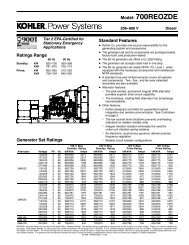
NORMAL & ABNORMAL FUEL CORRECTION<br />
Generally, the system is operating within specification<br />
when total fuel correction falls between -<br />
15% and +15%. Operation outside of this range<br />
will require further diagnosis to determine the system<br />
level issue affecting fuel control. The system<br />
will set Diagnostic Trouble Codes (DTC’s) for correction<br />
factors in the +/- 30%-35% range.<br />
If total fuel correction is found to be operating<br />
outside of the normal range additional diagnostic<br />
procedure will be required to determine the<br />
cause. Follow the appropriate Symptom Routine<br />
or DTC Chart for additional help.<br />
Total <strong>Fuel</strong> Correction Chart<br />
<strong>System</strong> Removing <strong>Fuel</strong><br />
<strong>System</strong> Adding <strong>Fuel</strong><br />
-35% -30% -25% -20% -15% -10% -5% 0% 5% 10% 15% 20% 25% 30% 35%<br />
= Normal <strong>Fuel</strong> Correction<br />
= Abnormal <strong>Fuel</strong> Correction without DTC<br />
= Abnormal <strong>Fuel</strong> Correction with DTC<br />
24
<strong>Fuel</strong> <strong>System</strong> Diagnosis<br />
Step Action Value(s) Yes No<br />
1 Were you referred to this procedure by a DTC diagnostic chart?<br />
2<br />
3<br />
1. Perform the On Board Diagnostic (OBD) <strong>System</strong> Check.<br />
Are any DTC’s present in the ECM?<br />
1. Verify that the fuel supply lines are connected properly without<br />
any kinks or damage<br />
Are fuel supply lines ok?<br />
Go to<br />
Step 3<br />
Go to the<br />
applicable<br />
DTC<br />
Table<br />
Go to<br />
Step 4<br />
Go to<br />
Step 2<br />
Go to<br />
Step 3<br />
Repair<br />
and Go<br />
to Step<br />
4<br />
4<br />
1. Connect the DST and start the engine and allow it to reach<br />
operating temperature.<br />
Does the engine start and run?<br />
Go to<br />
Step 5<br />
Go to<br />
Step 11<br />
5<br />
1. Bring the engine to operating speed and slowly increase the<br />
load in increments to full load.<br />
Does the engine pull full load?<br />
Go to<br />
Step 6<br />
Go to<br />
Step 13<br />
6<br />
1. Return the engine to its lowest operating speed and load.<br />
2. View the DST and make sure the fuel control mode is<br />
“Closed Loop + Adapt”. Note: The engine must be at 165°F<br />
or higher to reach this fuel control mode.<br />
Is the fuel control mode correct?<br />
Closed<br />
Loop +<br />
Adapt<br />
Go to<br />
Step 7<br />
Go to<br />
Step 22<br />
7<br />
3. Continue to run the engine at its lowest speed and load and<br />
check EGO1 voltage.<br />
Is EGO fluctuating rapidly?<br />
Go to<br />
Step 8<br />
Go to<br />
Step 23<br />
8<br />
1. Continue to operate the engine at its lowest speed and no<br />
load.<br />
2. Using the DST observe Closed Loop 1 and Adaptive 1 and<br />
calculate total fuel correction.<br />
Is total fuel correction within the specified range?<br />
-15%<br />
to<br />
+15%<br />
Go to<br />
Step 9<br />
Go to<br />
Step 24<br />
9<br />
1. Raise the engine rpm to operating speed and load the engine<br />
to a mid-load point.<br />
2. Using the DST observe Closed Loop 1 and Adaptive 1 and<br />
calculate total fuel correction.<br />
Is total fuel correction within the specified range?<br />
-15%<br />
to<br />
+15%<br />
Go to<br />
Step 10<br />
Go to<br />
Step 24<br />
25
Step Action Value(s) Yes No<br />
10<br />
1. Run the engine at operating speed and raise the load to fullload.<br />
2. Using the DST observe Closed Loop 1 and Adaptive 1 and<br />
calculate total fuel correction.<br />
3. Is total fuel correction within the specified range?<br />
-15%<br />
to<br />
+15%<br />
Go to 25<br />
Go to<br />
Step 24<br />
11<br />
1. Connect the DST<br />
2. Turn the key on and set the DST view to the “Faults” page<br />
3. Crank the engine and view the Gaseous Pressure Target and<br />
Gaseous Pressure Actual values.<br />
Is there fuel pressure registered in Gaseous Pressure Actual<br />
and does it match Gaseous Pressure Target within .5” w.c.?<br />
Go to<br />
Step 12<br />
Got to<br />
Step 14<br />
12<br />
4. Remove Air induction hose to the mixer.<br />
5. Observe the air valve for movement while the engine is<br />
cranking.<br />
Note: Movement of the air valve will be minimal at cranking<br />
speeds.<br />
Does the air valve move when the engine is cranked?<br />
Go to Ignition<br />
<strong>System</strong><br />
Test<br />
Go to<br />
Step 13<br />
13<br />
1. Inspect the air intake stream to the mixer assembly and the<br />
throttle body for vacuum leaks.<br />
Were vacuum leaks found and repaired?<br />
Return to<br />
Step 4<br />
Go to<br />
Step 21<br />
14<br />
1. Inspect the fuel supply hose between the source and the<br />
IEPR and the mixer assembly for damage or leakage.<br />
Was a problem found and repaired?<br />
Return to<br />
Step 4<br />
Go to<br />
Step 15<br />
15<br />
1. Connect a water column gauge or manometer to the fuel<br />
supply hose between the fuel source and the fuel shut off<br />
valve.<br />
Is fuel pressure in the specified range?<br />
7”-11”<br />
w.c.<br />
Go to<br />
Step 16<br />
Repair<br />
fuel<br />
source<br />
and<br />
Move to<br />
Step 4<br />
16<br />
1. Connect a water column gauge or manometer to the fuel<br />
supply hose between the fuel shut off valve and the IEPR.<br />
Is fuel pressure within specified range?<br />
7”-11”<br />
w.c.<br />
Go to<br />
Step 19<br />
Go to<br />
Step 17<br />
17<br />
1. Turn OFF the ignition.<br />
2. Connect volt meter across the harness side of the fuel shut<br />
off solenoid connector<br />
3. Crank the engine.<br />
Is voltage present?<br />
11-13<br />
volts<br />
Go to<br />
Step 20<br />
Go to<br />
Step 18<br />
26
Step Action Value(s) Yes No<br />
18<br />
19<br />
20<br />
21<br />
22<br />
23<br />
24<br />
1. Repair the open or broken electrical connection in the Shut-<br />
Off Valve circuit.<br />
Is the action complete?<br />
1. Replace the IEPR. Refer to Integrated Electronic Pressure<br />
Regulator Repair.<br />
Is the action complete?<br />
1. Replace the Shut-Off Valve. Refer to the Shut-Off Valve<br />
Replacement.<br />
Is the action complete?<br />
1. Replace the mixer assembly. Refer to <strong>Fuel</strong> Mixer Replacement.<br />
Is the action complete?<br />
Check that the engine is reaching normal operating temperature.<br />
If engine is not reaching temperature diagnose problem<br />
with cooling system. If engine is reaching 165°F and does not<br />
go into Closed Loop mode check operation of O2 sensor and<br />
recheck DTC’s.<br />
Was a problem found and repaired?<br />
Disconnect EGO1 connector and check heater circuit for 12V<br />
and ground. If present replace O2 sensor. If 12V and ground<br />
not present repair circuit. Check for DTC and follow DTC chart.<br />
Was a problem found and repaired?<br />
You were referred to this step because the total fuel correction<br />
was found to be out of tolerance. Check the system for pinched<br />
cut or disconnected vacuum hoses or electrical connections.<br />
Check for a restricted or missing air filter. Check for loose<br />
mounting hardware for the mixer and IEPR. Check to see that<br />
actual engine coolant temperature matches the <strong>Engine</strong> Coolant<br />
Temperature (ECT) reading with the DST.<br />
Was a problem found and corrected?<br />
Go to<br />
Step 25<br />
Go to<br />
Step 4<br />
and Restart<br />
Test<br />
Go to<br />
Step 4<br />
and Restart<br />
Test<br />
Go to<br />
Step 4<br />
and Restart<br />
Test<br />
Go to<br />
Step 6<br />
Go to<br />
Step 7<br />
Go to<br />
Step 4<br />
and restart<br />
Test<br />
Recheck<br />
DTC’s<br />
and try<br />
Additional<br />
Steps<br />
Recheck<br />
DTC’s<br />
and Repair<br />
Recheck<br />
DTC<br />
and follow<br />
DTC<br />
diagnosis<br />
Recheck<br />
DTC’s<br />
and try<br />
Additional<br />
Steps<br />
25<br />
The <strong>Fuel</strong> Control <strong>System</strong> is operating normally.<br />
Remove all test equipment.<br />
<strong>System</strong><br />
OK<br />
27
ADDITIONAL STEPS<br />
STEP ACTION VALUE(S) YES NO<br />
Go to<br />
1<br />
1. Perform the On-Board Diagnostic (OBD) <strong>System</strong> check.<br />
Applicable<br />
DTC Step 2<br />
Go to<br />
Are any DTCs present in the ECM?<br />
Table<br />
2 Has the <strong>Fuel</strong> system diagnosis been performed?<br />
3<br />
4<br />
5<br />
6<br />
7<br />
8<br />
9<br />
1. Replace the <strong>Engine</strong> Control Unit (ECM). Refer to <strong>Engine</strong><br />
Control Unit (ECM) replacement.<br />
Is this action complete?<br />
1. Repair the open or damaged circuit.<br />
Is this action complete?<br />
1. Return the fuel system to normal operating condition.<br />
2. Observe the Adaptive 1 fuel correction.<br />
3. Raise the engine speed to approximately 2500 rpm.<br />
Is the Adaptive 1 fuel correction within the specified range at<br />
idle and 2500 rpms?<br />
1. Check all vacuum hoses and mixer connections for leakage.<br />
Was a problem found?<br />
1. Replace Mixer.<br />
Is this action complete?<br />
1. The fuel control system is operating normally. Refer to<br />
Symptoms Diagnosis 1. Disconnect all test equipment 2.<br />
2. If you were sent to this routine by another diagnostic chart,<br />
retune to the previous diagnostic procedure.<br />
Is this action complete?<br />
1. Disconnect all test equipment<br />
2. Start the engine<br />
3. Using a liquid leak detection solution leak check any fuel<br />
system repairs made.<br />
Is this action complete?<br />
-15 to +15<br />
Go to<br />
Step 3<br />
Go to<br />
Step 5<br />
Go to<br />
Step 5<br />
Go to<br />
Step 9<br />
Go to<br />
Step 5<br />
Go to<br />
Step 5<br />
<strong>System</strong><br />
OK<br />
<strong>System</strong><br />
OK<br />
Go to <strong>Fuel</strong><br />
system<br />
Diagnosis<br />
Go to<br />
Step 4<br />
Go to<br />
Step 8<br />
Go to<br />
Step 6<br />
Go to<br />
Step 7<br />
Go to<br />
Step 9<br />
28
<strong>Fuel</strong> <strong>System</strong> Symptom<br />
Diagnostics<br />
29
FUEL SYSTEM SYMPTOM DIAGNOSTICS<br />
Checks<br />
Action<br />
Before using this section, you should have performed On Board Diagnostic<br />
(OBD) Check and determined that:<br />
Before Using This<br />
Section<br />
1. The ECM and MIL are operating correctly.<br />
2. There are no Diagnostic Trouble Codes (DTCs) stored, or a DTC exists<br />
but without a MIL.<br />
Several of the following symptom procedures call for a careful visual and<br />
physical check. These checks are very important as they can lead to prompt<br />
diagnosis and correction of a problem.<br />
<strong>Fuel</strong> <strong>System</strong> Check<br />
1. Verify the customer complaint.<br />
2. Locate the correct symptom table.<br />
3. Check the items indicated under that symptom.<br />
4. Operate the equipment under the conditions the symptom occurs. Verify<br />
HEGO switching between lean and rich. IMPORTANT! Normal HEGO<br />
switching indicates the fuel system is in closed loop and operating<br />
correctly at that time.<br />
5. Take a data snapshot using the DST under the condition that the symptom<br />
occurs to review at a later time.<br />
Check all ECM system fuses and circuit breakers.<br />
Check the ECM ground for being clean, tight and in its proper location.<br />
Check the vacuum hoses for splits, kinks and proper connections.<br />
Check thoroughly for any type of leak or restriction.<br />
Check for air leaks at all the mounting areas of the intake manifold sealing<br />
surfaces.<br />
Check for proper installation of the mixer assembly.<br />
Check for air leaks at the mixer assembly.<br />
Visual and Physical<br />
Checks<br />
Check the ignition wires for the following conditions:<br />
Cracking<br />
Hardening<br />
Proper routing<br />
Carbon tracking.<br />
Check the wiring for the following items: proper connections, pinches or<br />
cuts.<br />
The following symptom tables contain groups of possible causes for each<br />
symptom. The order of these procedures is not important. If the DST readings<br />
do not indicate a problem, then proceed in a logical order, easiest to<br />
check or most likely to cause the problem.<br />
30
INTERMITTENT<br />
Checks<br />
Action<br />
DEFINITION: The problem may or may not turn ON the (MIL) or store a Diagnostic Trouble Code (DTC).<br />
Preliminary Checks<br />
Do not use the DTC tables. If a fault is an intermittent, the use of the DTC<br />
tables with this condition may result in the replacement of good parts.<br />
Faulty electrical connections or wiring can cause most intermittent problems.<br />
Check the suspected circuit for the following conditions:<br />
Faulty Electrical Connections<br />
or Wiring<br />
Operational Test<br />
<br />
<br />
<br />
<br />
<br />
<br />
Faulty fuse or circuit breaker, connectors poorly mated, terminals not fully<br />
seated in the connector (backed out). Terminals not properly formed or<br />
damaged.<br />
Wire terminals poorly connected.<br />
Terminal tension is insufficient.<br />
Carefully remove all the connector terminals in the problem circuit in order<br />
to ensure the proper contact tension.<br />
If necessary, replace all the connector terminals in the problem circuit in<br />
order to ensure the proper contact tension (except those noted as “Not<br />
Serviceable”). See section Wiring Schematics.<br />
Checking for poor terminal to wire connections requires removing the<br />
terminal from the connector body.<br />
If a visual and physical check does not locate the cause of the problem, operate<br />
the vehicle with the DST connected. When the problem occurs, an<br />
abnormal voltage or scan reading indicates a problem circuit.<br />
The following components can cause intermittent MIL and no DTC(s):<br />
Intermittent MIL<br />
Illumination<br />
Loss of DTC Memory<br />
A defective relay.<br />
Switch that can cause electrical system interference. Normally, the problem<br />
will occur when the faulty component is operating.<br />
The improper installation of add on electrical devices, such as lights, 2-<br />
way radios, electric motors, etc.<br />
The ignition secondary voltage shorted to a ground.<br />
The MIL circuit or the Diagnostic Test Terminal intermittently shorted to<br />
ground.<br />
The MIL wire grounds.<br />
To check for the loss of the DTC Memory:<br />
1. Disconnect the TMAP sensor.<br />
2. Idle the engine until the MIL illuminates.<br />
3. The ECM should store a TMAP DTC which should remain in the memory<br />
when the ignition is turned OFF. If the TMAP DTC does not store and<br />
remain, the ECM is faulty.<br />
31
NO START<br />
Checks<br />
Action<br />
DEFINITION: The engine cranks OK but does not start.<br />
Preliminary Checks None<br />
Use the DST to :<br />
Check for proper communication with both the ECM<br />
Check all system fuses engine fuse holder. Refer to <strong>Engine</strong> Controls<br />
ECM Checks<br />
Schematics.<br />
Check battery power, ignition power and ground circuits to the ECM. Refer<br />
to <strong>Engine</strong> Control Schematics. Verify voltage and/or continuity for<br />
each.<br />
Check the TMAP sensor.<br />
Sensor Checks<br />
Check the cam angle sensor for output (RPM).<br />
Important: A closed LPG manual fuel shut off valve will create a no start<br />
condition.<br />
<strong>Fuel</strong> <strong>System</strong> Checks<br />
<br />
<br />
<br />
<br />
<br />
Check for air intake system leakage between the mixer and the throttle<br />
body. Verify proper operation of the low pressure lock-off solenoids.<br />
Verify proper operation of the fuel control solenoids.<br />
Check the fuel system pressures.<br />
Refer to the LPG <strong>Fuel</strong> <strong>System</strong> Diagnosis.<br />
Check for proper mixer air valve operation.<br />
Note: LPG being a gaseous fuel requires higher secondary ignition system<br />
voltages for the equivalent gasoline operating conditions.<br />
1. Check for the proper ignition voltage output with J 26792 or the equivalent.<br />
2. Verify that the spark plugs are correct for use with LPG.<br />
Ignition <strong>System</strong> Checks<br />
Check the spark plugs for the following conditions:<br />
Wet plugs.<br />
Cracks.<br />
Wear.<br />
Improper gap.<br />
Burned electrodes.<br />
Heavy deposits.<br />
Check for bare or shorted ignition wires.<br />
Check for loose ignition coil connections at the coil.<br />
32
NO START<br />
Checks<br />
Action<br />
Important: The LPG <strong>Fuel</strong> system is more sensitive to intake manifold leakage<br />
than the gasoline fuel system.<br />
<strong>Engine</strong> Mechanical<br />
Checks<br />
Exhaust <strong>System</strong><br />
Checks<br />
Check for the following:<br />
Vacuum leaks.<br />
Improper valve timing.<br />
Low compression.<br />
Improper valve clearance.<br />
Worn rocker arms.<br />
Broken or weak valve springs.<br />
Worn camshaft lobes.<br />
Check the exhaust system for a possible restriction:<br />
Inspect the exhaust system for damaged or collapsed pipes:<br />
Inspect the muffler for signs of heat distress or for possible internal failure.<br />
Check for possible plugged catalytic converter. Refer to Restricted Exhaust<br />
<strong>System</strong> Diagnosis.<br />
33
Checks<br />
HARD START<br />
Action<br />
DEFINITION: The engine cranks OK, but does not start for a long time. The engine does eventually run,<br />
or may start but immediately dies.<br />
Preliminary Checks<br />
Sensor Checks<br />
<strong>Fuel</strong> <strong>System</strong> Checks<br />
Make sure the vehicle’s operator is using the correct starting procedure.<br />
<br />
<br />
Check the <strong>Engine</strong> Coolant Temperature sensor with the DST. Compare<br />
the engine coolant temperature with the ambient air temperature on a<br />
cold engine. If the coolant temperature reading is more than 10 degrees<br />
greater or less than the ambient air temperature on a cold engine, check<br />
for high resistance in the coolant sensor circuit. Check the cam angle<br />
sensor.<br />
Check the Throttle Position (TPS) and Foot Pedal Position (FPP) sensor<br />
connections.<br />
Important: A closed LPG manual fuel shut off valve will create an extended<br />
crank OR no start condition.<br />
<br />
Verify the excess hut-off<br />
valve is not closed.<br />
Check mixer assembly for proper installation and leakage.<br />
Verify proper operation of the low pressure lock-off solenoid.<br />
Verify proper operation of the EPR.<br />
Check for air intake system leakage between the mixer and the throttle<br />
body. Check the fuel system pressures. Refer to the <strong>Fuel</strong> <strong>System</strong> Diagnosis.<br />
Note: LPG being a gaseous fuel requires higher secondary ignition system<br />
voltages for the equivalent gasoline operating conditions.<br />
<br />
<br />
Check for the proper ignition voltage output with J 26792 or the equivalent.<br />
Verify that the spark plugs are the correct type and properly gapped.<br />
Ignition <strong>System</strong> Checks<br />
Check the spark plugs for the following conditions:<br />
Wet plugs.<br />
Cracks.<br />
Wear.<br />
Burned electrodes.<br />
Heavy deposits<br />
Check for bare or shorted ignition wires.<br />
Check for moisture in the distributor cap.<br />
Check for loose ignition coil connections.<br />
Important:<br />
1. If the engine starts but then immediately stalls, check the cam angle sensor.<br />
2. Check for improper gap, debris or faulty connections.<br />
34
HARD START<br />
Checks<br />
<strong>Engine</strong> Mechanical<br />
Checks<br />
Action<br />
Important: The LPG <strong>Fuel</strong> system is more sensitive to intake manifold leakage<br />
than the gasoline fuel supply system.<br />
Check for the following:<br />
Vacuum leaks<br />
Improper valve timing<br />
Low compression<br />
Improper valve clearance.<br />
Worn rocker arms<br />
Broken or weak valve springs<br />
Worn camshaft lobes.<br />
Check the intake and exhaust manifolds for casting <br />
Check the exhaust system for a possible restriction:<br />
Exhaust <strong>System</strong> Checks<br />
<br />
<br />
Inspect the exhaust system for damaged or collapsed pipes.<br />
Inspect the muffler for signs of heat distress or for possible internal failure.<br />
Check for possible plugged catalytic converter. Refer to Restricted Exhaust<br />
<strong>System</strong> Diagnosis.<br />
35
CUTS OUT, MISSES<br />
Checks<br />
Action<br />
DEFINITION: A surging or jerking that follows engine speed, usually more pronounced as the engine load<br />
increases, but normally felt below 1500 RPM. The exhaust has a steady spitting sound at idle, low speed,<br />
or hard acceleration for the fuel starvation that can cause the engine to cut-out.<br />
Preliminary Checks<br />
None<br />
1. Start the engine.<br />
2. Check for proper ignition output voltage with spark tester J 26792.<br />
3. Check for a cylinder mis<br />
4. Verify that the spark plugs are the correct type and properly gapped.<br />
Remove the spark plugs and check for the following conditions:<br />
Ignition <strong>System</strong> Checks<br />
<br />
<br />
<br />
<br />
<br />
Insulation cracks.<br />
Wear.<br />
Improper gap.<br />
Burned electrodes.<br />
Heavy deposits.<br />
Visually/Physically inspect the secondary ignition for the following:<br />
Ignition wires for arcing and proper routing.<br />
Cross-.<br />
Ignition coils for cracks or carbon tracking<br />
Perform a cylinder compression check. Check the engine for the following:<br />
<strong>Engine</strong> Mechanical<br />
Checks<br />
<strong>Fuel</strong> <strong>System</strong> Checks<br />
Additional Check<br />
Improper valve timing.<br />
Improper valve clearance.<br />
Worn rocker arms.<br />
Worn camshaft lobes.<br />
Broken or weak valve springs.<br />
Check the intake and exhaust manifold passages for casting <br />
Check the fuel system:<br />
<br />
<br />
<br />
Plugged fuel .<br />
Low fuel pressure, etc. Refer to LPG <strong>Fuel</strong> <strong>System</strong> Diagnosis.<br />
Check the condition of the wiring to the low pressure lock-off solenoid.<br />
Check for Electromagnetic Interference (EMI), which may cause a misfire condition.<br />
Using the DST, monitor the engine RPM and note sudden increases in<br />
rpms displayed on the scan tool but with little change in the actual engine rpm.<br />
If this condition exists, EMI may be present. Check the routing of the secondary<br />
wires and the ground circuit.<br />
36
HESITATION, SAG, STUMBLE<br />
Checks<br />
Action<br />
DEFINITION: The engine has a momentary lack of response when putting it under load. The condition<br />
can occur at any engine speed. The condition may cause the engine to stall if it’s severe enough.<br />
Preliminary Checks None.<br />
Check the fuel pressure. Refer to LPG <strong>Fuel</strong> <strong>System</strong> Diagnosis.<br />
Check for low fuel pressure during a moderate or full throttle acceleration.<br />
If the fuel pressure drops below speci<br />
faulty low pressure regulator or a restriction in the fuel system.<br />
<strong>Fuel</strong> <strong>System</strong> Checks Check the TMAP sensor response and accuracy.<br />
Check Shut-Off electrical connection.<br />
Check the mixer air valve for sticking or binding.<br />
Check the mixer assembly for proper installation and leakage. Check the<br />
EPR.<br />
Ignition <strong>System</strong> Checks<br />
Note: LPG being a gaseous fuel requires higher secondary ignition system<br />
voltages for the equivalent gasoline operating conditions. If a problem is reported<br />
on LPG and not gasoline, do not discount the possibility of a LPG only<br />
ignition system failure and test the system accordingly.<br />
<br />
<br />
<br />
Check for the proper ignition voltage output with J 26792 or the equivalent.<br />
Verify that the spark plugs are the correct type and properly<br />
gapped.<br />
Check for faulty spark plug wires.<br />
Check for fouled spark plugs.<br />
Additional Check<br />
<br />
<br />
Check for manifold vacuum or air induction system leaks.<br />
Check the alternator output voltage.<br />
37
BACKFIRE<br />
Checks<br />
Action<br />
DEFINITION: The fuel ignites in the intake manifold, or in the exhaust system, making a loud popping<br />
noise.<br />
Preliminary Check None.<br />
Important! LPG, being a gaseous fuel, requires higher secondary ignition<br />
system voltages for the equivalent gasoline operating conditions.<br />
The ignition system must be maintained in peak condition to prevent<br />
backre.<br />
Ignition <strong>System</strong> Checks<br />
<br />
<br />
<br />
<br />
Check for the proper ignition coil output voltage using the spark tester<br />
J26792 or the equivalent.<br />
Check the spark plug wires by connecting an ohmmeter to the ends of<br />
each wire in question. If the meter reads over 30,000 ohms, replace the<br />
wires.<br />
Check the connection at ignition coil.<br />
Check for deteriorated spark plug wire insulation.<br />
Remove the plugs and inspect them for the following conditions:<br />
Wet plugs.<br />
Cracks.<br />
Wear.<br />
Improper gap.<br />
Burned electrodes.<br />
Heavy deposits.<br />
Important! The LPG <strong>Fuel</strong> system is more sensitive to intake manifold<br />
leakage than a gasoline fuel supply system.<br />
<strong>Engine</strong> Mechanical<br />
Check<br />
<strong>Fuel</strong> <strong>System</strong> Checks<br />
Check the engine for the following:<br />
Improper valve timing.<br />
<strong>Engine</strong> compression.<br />
Manifold vacuum leaks.<br />
Intake manifold gaskets.<br />
Sticking or leaking valves.<br />
Exhaust system leakage.<br />
Check the intake and exhaust system for casting ctions.<br />
Perform a fuel system diagnosis. Refer to LPG <strong>Fuel</strong> <strong>System</strong> Diagnosis.<br />
38
LACK OF POWER, SLUGGISHNESS, OR SPONGINESS<br />
Checks<br />
DEFINITION: The engine delivers less than expected power.<br />
Action<br />
Preliminary Checks<br />
<br />
<br />
<br />
<br />
<br />
Refer to the LPG <strong>Fuel</strong> system OBD <strong>System</strong> Check.<br />
Compare the customer’s vehicle with a similar unit to verify customer has<br />
an actual problem. Do not compare the power output of the vehicle operating<br />
on LPG to a vehicle operating on gasoline as the fuels do have<br />
different drive feel characteristics.<br />
Remove the air <br />
Check the vehicle transmission.<br />
Refer to the OEM transmission diagnostics.<br />
<strong>Fuel</strong> <strong>System</strong> Checks<br />
Check for a restricted fuel ssure.<br />
Refer to LPG <strong>Fuel</strong> <strong>System</strong> Diagnosis.<br />
Check for the proper ignition output voltage with the spark tester J 26792<br />
or the equivalent.<br />
Check for proper installation of the mixer assembly. Check all air inlet<br />
ducts for condition and proper installation.<br />
Check for fuel leaks between the EPR and the mixer.<br />
Verify that the LPG tank manual shut-off valve is fully open.<br />
Verify that liquid fuel (not vapor) is being delivered to the EPR.<br />
Sensor Checks<br />
<br />
<br />
Check the Heated Exhaust Gas Oxygen Sensors (HEGO) for contamination<br />
and performance. Check for proper operation of the TMAP sensor.<br />
Check for proper operation of the TPS and FPP sensors.<br />
Exhaust <strong>System</strong> Checks<br />
<strong>Engine</strong> Mechanical<br />
Check<br />
Additional Check<br />
Check the exhaust system for a possible restriction:<br />
Inspect the exhaust system for damaged or collapsed pipes.<br />
Inspect the muffler for signs of heat distress or for possible internal failure.<br />
Check for possible plugged catalytic converter.<br />
Check the engine for the following:<br />
<strong>Engine</strong> compression.<br />
Valve timing.<br />
Improper or worn camshaft.<br />
Refer to <strong>Engine</strong> Mechanical in the Service Manual.<br />
Check the ECM grounds for being clean, tight, and in their proper locations.<br />
Check the alternator output voltage.<br />
If all procedures have been completed and no malfunction has been found,<br />
review and inspect the following items:<br />
Visually and physically, inspect all electrical connections within the suspected<br />
circuit and/or systems.<br />
Check the DST data.<br />
39
Checks<br />
ROUGH, UNSTABLE, OR INCORRECT IDLE, STALLING<br />
Action<br />
DEFINITION: The engine runs unevenly at idle. If severe enough, the engine may shake.<br />
Preliminary Check<br />
Sensor Checks<br />
None.<br />
Check the Heated Exhaust Gas Oxygen Sensors (HEGO) performance:<br />
Check for silicone contamination from fuel or improperly used sealant. If<br />
contaminated, the sensor may have a white powdery coating result in a<br />
high but false signal voltage (rich exhaust indication). The ECM will reduce<br />
the amount of fuel delivered to the engine causing a severe<br />
driveability problem.<br />
Check the Temperature Manifold Absolute Pressure (TMAP) sensor response<br />
and accuracy.<br />
<strong>Fuel</strong> <strong>System</strong> Checks<br />
<br />
<br />
<br />
<br />
<br />
<br />
<br />
<br />
<br />
<br />
Check for rich or lean symptom that causes the condition.<br />
Drive the vehicle at the speed of the complaint.<br />
Monitoring the oxygen sensors will help identify the problem.<br />
Check for a sticking mixer air valve.<br />
Verify proper operation of the EPR.<br />
Perform a cylinder compression test. Refer to <strong>Engine</strong> Mechanical in the<br />
Service Manual.<br />
Check the EPR fuel pressure. Refer to the LPG <strong>Fuel</strong> <strong>System</strong> Diagnosis.<br />
Check mixer assembly for proper installation and connection.<br />
Check for the proper ignition output voltage using the spark tester<br />
J26792 or the equivalent.<br />
Verify that the spark plugs are the correct type and properly gapped.<br />
Ignition <strong>System</strong> Checks<br />
Remove the plugs and inspect them for the following conditions:<br />
Wet plugs.<br />
Cracks.<br />
Wear.<br />
Improper gap.<br />
Burned electrodes.<br />
Blistered insulators.<br />
Heavy deposits.<br />
Check the spark plug wires by connecting an ohmmeter to the ends of each<br />
wire in question. If the meter reads over 30,000 ohms, replace the wires.<br />
Important: The LPG <strong>Fuel</strong> system is more sensitive to intake manifold leakage<br />
than the gasoline fuel supply system.<br />
Additional Checks<br />
<br />
<br />
Check for vacuum leaks. Vacuum leaks can cause a higher than normal<br />
idle and low throttle angle control command.<br />
Check the ECM grounds for being clean, tight, and in their proper locations.<br />
Check the battery cables and ground straps. They should be clean<br />
and secure. Erratic voltage may cause all sensor readings to be skewed<br />
resulting in poor idle quality.<br />
40
ROUGH, UNSTABLE, OR INCORRECT IDLE, STALLING<br />
Checks<br />
<strong>Engine</strong> Mechanical<br />
Check<br />
Check the engine for:<br />
Broken motor mounts.<br />
Improper valve timing.<br />
Low compression.<br />
Improper valve clearance.<br />
Worn rocker arms.<br />
Broken or weak valve springs.<br />
Worn camshaft lobes.<br />
Action<br />
41
Electrical Section<br />
NOTE: YOU CAN OBTAIN A FULL SIZE ELECTRONIC WIRE DIAGRAM BY CONTACTING THE OEM.<br />
42
DRAWING NUMBER<br />
REV:<br />
32501682 B<br />
MATERIAL:<br />
REFERENCE<br />
E2322101<br />
UNLESS SPECIFIED OTHERWISE<br />
.XX .030; .XXX .010 (in.)<br />
ANGLE DIMENSIONS : 1°<br />
GEOMETRIC DIMENSIONS PER ASME Y14.5M-1994<br />
REV. DESCRIPTION BY DATE APPROVED<br />
Solidworks<br />
DRAWN BY:<br />
JMA<br />
DRAW DATE:<br />
1/22/2010<br />
APP'D / DATE:<br />
NAME:<br />
SFH 1/25/10<br />
POWER PRODUCTION INC.<br />
655 WHEAT LANE WOOD DALE, IL. 60191<br />
POWER PRODUCTION INC. CLAIMS PROPRIETARY-<br />
CONFIDENTIAL RIGHTS TO ALL INFORMATION ON THIS DRAWING.<br />
HARNESS, 1.6L<br />
STATIONARY, IEPR (SCHEMATIC)<br />
EXPERIMENTAL. NO:<br />
-<br />
PRODUCTION NO: REV: SHEET:<br />
32501682 B 1 of 1
DRAWING NUMBER<br />
32501683 REV:<br />
-<br />
MATERIAL:<br />
REFERENCE<br />
E2322301<br />
UNLESS SPECIFIED OTHERWISE<br />
.XX .030; .XXX .010 (in.)<br />
ANGLE DIMENSIONS : 1°<br />
GEOMETRIC DIMENSIONS PER ASME Y14.5M-1994<br />
REV. DESCRIPTION BY DATE APPROVED<br />
Solidworks<br />
DRAWN BY:<br />
JMA<br />
DRAW DATE:<br />
1/22/2010<br />
APP'D / DATE:<br />
SFH 1/25/10<br />
NAME:<br />
POWER PRODUCTION INC.<br />
655 WHEAT LANE WOOD DALE, IL. 60191<br />
POWER PRODUCTION INC. CLAIMS PROPRIETARY-<br />
CONFIDENTIAL RIGHTS TO ALL INFORMATION ON THIS DRAWING.<br />
HARNESS, 3.0L<br />
STATIONARY, IEPR (SCHEMATIC)<br />
EXPERIMENTAL. NO:<br />
-<br />
PRODUCTION NO:<br />
32501683<br />
REV:<br />
-<br />
SHEET:<br />
1 of 1
DRAWING NUMBER<br />
32501684 REV:<br />
-<br />
MATERIAL:<br />
REFERENCE<br />
E2322401<br />
UNLESS SPECIFIED OTHERWISE<br />
.XX .030; .XXX .010 (in.)<br />
ANGLE DIMENSIONS : 1°<br />
GEOMETRIC DIMENSIONS PER ASME Y14.5M-1994<br />
REV. DESCRIPTION BY DATE APPROVED<br />
Solidworks<br />
DRAWN BY:<br />
JMA<br />
DRAW DATE:<br />
1/22/2010<br />
APP'D / DATE:<br />
SFH 1/25/10<br />
NAME:<br />
POWER PRODUCTION INC.<br />
655 WHEAT LANE WOOD DALE, IL. 60191<br />
POWER PRODUCTION INC. CLAIMS PROPRIETARY-<br />
CONFIDENTIAL RIGHTS TO ALL INFORMATION ON THIS DRAWING.<br />
HARNESS 4.3L<br />
STATIONARY, IEPR (SCHEMATIC)<br />
EXPERIMENTAL. NO:<br />
-<br />
PRODUCTION NO:<br />
32501684<br />
REV:<br />
-<br />
SHEET:<br />
1 of 1
DRAWING NUMBER<br />
32501685 A REV: Solidworks<br />
MATERIAL:<br />
REFERENCE<br />
E2322501<br />
UNLESS SPECIFIED OTHERWISE<br />
.XX .030; .XXX .010 (in.)<br />
ANGLE DIMENSIONS : 1°<br />
GEOMETRIC DIMENSIONS PER ASME Y14.5M-1994<br />
REV. DESCRIPTION BY DATE APPROVED<br />
DRAWN BY:<br />
JMA<br />
DRAW DATE:<br />
1/22/2010<br />
APP'D / DATE:<br />
SFH 1/25/10<br />
NAME:<br />
POWER PRODUCTION INC.<br />
655 WHEAT LANE WOOD DALE, IL. 60191<br />
POWER PRODUCTION INC. CLAIMS PROPRIETARY-<br />
CONFIDENTIAL RIGHTS TO ALL INFORMATION ON THIS DRAWING.<br />
HARNESS, 5.0L/5.7L<br />
STAT., IEPR (SCHEMATIC)<br />
EXPERIMENTAL. NO:<br />
-<br />
PRODUCTION NO:<br />
32501685<br />
REV:<br />
A<br />
SHEET:<br />
1 of 1
DRAWING NUMBER<br />
33000959 REV:<br />
-<br />
MATERIAL:<br />
REFERENCE<br />
E2322802<br />
UNLESS SPECIFIED OTHERWISE<br />
.XX .030; .XXX .010 (in.)<br />
ANGLE DIMENSIONS : 1°<br />
GEOMETRIC DIMENSIONS PER ASME Y14.5M-1994<br />
REV. DESCRIPTION BY DATE APPROVED<br />
Solidworks<br />
DRAWN BY:<br />
JMA<br />
DRAW DATE:<br />
1/22/2010<br />
APP'D / DATE:<br />
SFH 1/25/10<br />
NAME:<br />
POWER PRODUCTION INC.<br />
655 WHEAT LANE WOOD DALE, IL. 60191<br />
POWER PRODUCTION INC. CLAIMS PROPRIETARY-<br />
CONFIDENTIAL RIGHTS TO ALL INFORMATION ON THIS DRAWING.<br />
HARNESS, NA STAT<br />
BI-EPR 8.1L (SCHEMATIC)<br />
EXPERIMENTAL. NO:<br />
-<br />
PRODUCTION NO:<br />
33000959<br />
REV:<br />
-<br />
SHEET:<br />
1 of 1
DRAWING NUMBER<br />
REV:<br />
32501673 -<br />
MATERIAL:<br />
REFERENCE<br />
E2322801<br />
UNLESS SPECIFIED OTHERWISE<br />
.XX .030; .XXX .010 (in.)<br />
ANGLE DIMENSIONS : 1°<br />
GEOMETRIC DIMENSIONS PER ASME Y14.5M-1994<br />
REV. DESCRIPTION BY DATE APPROVED<br />
Solidworks<br />
DRAWN BY:<br />
JMA<br />
DRAW DATE:<br />
1/22/2010<br />
APP'D / DATE:<br />
SFH 1/25/10<br />
NAME:<br />
POWER PRODUCTION INC.<br />
655 WHEAT LANE WOOD DALE, IL. 60191<br />
POWER PRODUCTION INC. CLAIMS PROPRIETARY-<br />
CONFIDENTIAL RIGHTS TO ALL INFORMATION ON THIS DRAWING.<br />
HARNESS, GCP<br />
STATIONARY 8.1L (SCHEMATIC)<br />
EXPERIMENTAL. NO:<br />
-<br />
PRODUCTION NO:<br />
32501673<br />
REV:<br />
-<br />
SHEET:<br />
1 of 1
Diagnostic Scan Tool (DST)<br />
49
CONTENTS<br />
<br />
<br />
<br />
<br />
<br />
Installation of the DST package to a personal computer (PC).<br />
Software login and password functionality.<br />
DST service pages.<br />
Updating the ECM calibration using a MOT file.<br />
DTC pages.<br />
Examples and snapshots used in this manual are based off of the initial DST tool release as of July,<br />
2007. This tool is frequently updated and the illustrations may vary depending on the changes included<br />
in any updated DST display Interface. For example, the Electronic Pressure Regulator (EPR)<br />
may be referred to as the “megajector.” Terms, names and descriptions of parts and servicing procedures<br />
will be updated based on trade, brand, or common description to more accurately describe the<br />
part or service procedure.<br />
DST INSTALLATION INSTRUCTIONS<br />
Before installing the DST software, please be sure your computer meets the minimum system requirements.<br />
Supported operating systems are:<br />
Windows Vista<br />
Windows XP<br />
Windows 2000<br />
Minimum processor speed:<br />
<br />
<br />
Pentium II 450 MHz<br />
Pentium III 1.0 GHz for Windows Vista<br />
Minimum RAM requirement:<br />
<br />
<br />
<br />
Windows Vista 512 MB<br />
Windows XP 256 MB<br />
Windows 2000 128 MB<br />
* At least one available RS232 serial or USB port.<br />
* ECOM cable supports USB port only.<br />
50
Insert the CD into your computer and select LATEST_GCP_DISPLAY<br />
<br />
Open the ECOM_Driver Folder<br />
51
Double Click the setup.exe file - - - > This will launch the installation wizard<br />
Select “NEXT” until you finish the installation as shown below<br />
<br />
Return to the LATEST_GCP_DISPLAY folder<br />
52
Select the PC Display folder<br />
<br />
Select the GCP Display icon<br />
<br />
<br />
<br />
<br />
Select the GCP Display icon - - - > This will launch the installation wizard<br />
Select NEXT until it says you are finish<br />
Restart your PC<br />
Go to the START button on the lower<br />
left corner and find the GCP Display<br />
Program<br />
53
PASSWORD LOGIN<br />
Figure 1 shows the password dialog box, which is displayed when a software session begins. Login<br />
can be accomplished in two ways.<br />
1. Enter an “All S/N Password” which is a password applicable to all ECMs of a given original<br />
equipment manufacture (OEM).<br />
2. Enter a “Single S/N Password” and corresponding ECM serial number for a single ECM. A Single<br />
Serial Number password is unique to a specific ECM serial number and permits authorized<br />
service personnel to make changes or view information for a specific ECM.<br />
3. In most instances the top “all” serial number boxes should be used for password entry. In this<br />
case, do not check the single serial number box. Each password is a 16-character alphanumeric<br />
string specific to each Spectrum customer and determines which pages and variables<br />
are visible through the software. Passwords are assigned by the OEM support group and may<br />
change periodically. Check the “save password” box to automatically retain the password for future<br />
use.<br />
Note: The password is printed on the CD disk. If it does not have a password or you have questions<br />
please contact the OEM.<br />
Figure 1: Populated Password Dialog Box<br />
PASSWORD DIALOG BOX FUNCTIONS<br />
Clear Password Button Erases the current password from the password field.<br />
Paste Password Button Allows the user to copy a 16-character string from any word processor<br />
and paste the string in the password field.<br />
Single Serial Number Access Checkbox Tells the software that the password is applicable for<br />
single serial number access.<br />
Serial Number Field Only applicable when Single Serial Number Access Checkbox is checked.<br />
The entry field must be populated for the 6-digit serial number for which the Single Serial Number<br />
Access password applies (NOTE: Leading zeros included in the serial number are not<br />
required).<br />
Save Password and S/N Checkbox Retains the password, and serial number (if applicable) for<br />
the next software session.<br />
54
Should an invalid password be entered, the error prompt shown in figure (2) will be displayed<br />
and the software will not load. This prompt signifies the following:<br />
The All S/N password is invalid.<br />
The Single S/N password is incorrect for the Single Serial Number entered.<br />
An All S/N password is entered for Single Serial Number use.<br />
The Single Serial Number password is valid; however, the Single Serial Number Access Checkbox<br />
is not checked.<br />
Figure 2: Password Error Prompt<br />
If the Single S/N password entered is correct for the software but does not match the entered S/N<br />
of the targeted ECM, the prompt in Figure 3 will be displayed.<br />
Figure 3: Incorrect Serial Number Message<br />
55
Figure 4 shows the communication status if a valid software password is entered when attempting<br />
to connect to an ECM with a different key. In this instance the software will load but will not connect<br />
to the target (ECM).<br />
Figure 4: Not Authorized to Connect Message<br />
In the event you receive this error message call your OEM support group for more information.<br />
CONNECTING THE PC TO THE ENGINE WIRE HARNESS<br />
Connecting the DST cable<br />
A laptop computer, with the diagnostic cable and software is the required tool for performing proper<br />
diagnostic testing of the fuel system. It is also used to monitor sensor and actuator values and to<br />
read and clear Diagnostic Trouble codes. The DST software also performs several special tests.<br />
Connect the system diagnostic cable to the USB port on the back of the computer.<br />
Connect the diagnostic cable to the DLC (diagnostic link connector) labeled in the electrical<br />
schematic. The DLC is located on the engine harness. The new 8 pin DLC requires the use of<br />
the 4 to 8 pin adapter.<br />
Turn the computer ON.<br />
Start Windows.<br />
From the start menu select Programs <strong>PSI</strong> GCP Display <strong>PSI</strong> GCP Display<br />
Place the ignition key in the ON position.<br />
Within several seconds the system Gauge screen should now appear and a green banner in the<br />
upper left hand will read “Connected.”<br />
56
Connecting to the PC using the ECOM cable<br />
<br />
To connect using the ECOM cable you must select ECOM from the COM Port drop down menu.<br />
57
You will now need to configure the ECOM communication protocol.<br />
<br />
Select the CAN for systems with CAN enabled or serial for all others. Then select OK. You<br />
are now ready to connect using the ECOM USB DLC cable.<br />
58
DST SERVICE PAGES<br />
Gauge Page<br />
Provides system data in large easy to read displays. Displays ECM configuration information for<br />
the ECM software, hardware, serial numbers and calibration dates.<br />
59
Raw Volts Page<br />
The raw volts page displays the sensor inputs and outputs in a raw voltage format. This page is<br />
most commonly used to check values in the diagnostic trouble shooting charts.<br />
Service 1<br />
60
The Service 1 screen is used to clear the adaptive learn, shows the MIL status and provides a display<br />
for rpm, coolant temperature and spark advance. It also provides a large display to monitor<br />
the closed loop mixture control.<br />
Tests Page<br />
Provides diagnostic information voltages and sensor outputs and includes diagnostic engine tools<br />
such as spark and injector kill controls. Please note that not all features are available for all applications.<br />
The disabled item menus are grayed out or rendered inoperative.<br />
SPARK KILL<br />
The spark kill mode allows the technician to disable the ignition on individual cylinders. If the<br />
Spark Kill diagnostic mode is selected with the engine running below 1000 rpm, the minimum throttle<br />
command will lock into the position it was in when the test mode was entered. If the Spark<br />
<strong>System</strong> Test mode is selected with the engine running above 1000 rpm, the throttle will continue to<br />
operate normally. Disabling Ignition Outputs to disable the ignition system for an individual cylinder,<br />
use the mouse to highlight the “Spark Kill” button and select the desired coil. The spark output<br />
can be re-enabled by using the mouse to highlight the “Spark Kill” button and selecting “Normal.” If<br />
the engine is running below 1000 rpm, the spark output will stay disabled for 15 seconds and then<br />
re-set. If the engine is running above 1000 rpm, the spark output will stay disabled for 5 seconds<br />
and then re-set. This test mode has a timeout of 10 minutes. Record the rpm drop related to each<br />
spark output disabled. The spark outputs are arranged in the order which the engine fires, not by<br />
cylinder number.<br />
INJECTOR KILL<br />
The Injector Kill mode is used to disable individual fuel injectors. If the Injector Kill mode is selected<br />
with the engine running below 1000 rpm, the minimum throttle command will lock into the<br />
position it was in when the test mode was entered. If the Injector Kill mode is selected with the<br />
engine running above 1000 rpm, the throttle will continue to operate normally. To disable an injector,<br />
use the mouse to select the desired injector. The word “Normal” will change to the<br />
Injector you have selected. The injector driver can be re-enabled by selecting again. If the engine<br />
is running below 1000 rpm, the injector driver will stay disabled for 15 seconds and then re-<br />
61
set. If the engine is running above 1000 rpm, the injector driver will stay disabled for 5 seconds<br />
and then re-set. Record the change in rpm while each driver is disabled.<br />
DBW TEST MODE<br />
The DBW (Drive by Wire) test mode allows the technician to control the throttle directly with the<br />
foot pedal or throttle input and is used during the diagnostic routines specified for FPP and TPS<br />
for Spectrum systems that use DBW control. FPP position displays the current position of the<br />
foot pedal as a percentage. FPP volts display the voltage which the ECM is reading from the<br />
FPP sensor. TPS Command displays the commanded throttle position expressed as a percentage,<br />
which is being sent to the throttle. TPS Position is the actual percent of throttle opening<br />
being sent to the ECM from the throttle. TPS volts display the actual TPS signal voltage the<br />
ECM is receiving from the throttle. To select this test mode the engine must be off and the key<br />
must be in the ON position.<br />
EXTERNAL POWER TEST<br />
The external power test manually activates relays (relay power, fuel pump, and drive-by wire<br />
power) controlled by the ECM while the engine is in the “Stopped” or “Running” states. Reverts<br />
to normal operation if “Automatic” state is selected or ignition voltage is cycled from high to low.<br />
Faults Page<br />
Stores DTC codes that may have occurred in the past (Historic Faults) or current set codes (Active<br />
Faults). Includes useful system voltages and sensor readings used while working with the fuel and<br />
emission trouble shooting charts. Shows power derate mode status. To erase a historic DTC<br />
code, double click on the code with the left mouse button. Then choose to “Clear All Faults.”<br />
62
PLOT/LOG MENU FUNCTIONS<br />
The Plot/Log menu allows the user to graphically plot or numerically log variables that have been<br />
tagged for plotting/logging. To plot or log variables, a tag must be assigned to each variable of interest.<br />
A variable is tagged for plotting/logging through a single right-mouse click in the variable’s<br />
vicinity. Once a variable has been tagged for plotting/logging, it is highlighted in green.<br />
Figure 5 shows an example of variables that have been tagged. A maximum of twenty (20) variables<br />
may be tagged for logging and a maximum of ten (10) variables may be tagged for plotting.<br />
The maximum achievable sample frequency/minimum period is dependent on the number of variables<br />
tagged.<br />
Figure 5: Tagged Variables for Plot/Log<br />
Once the variables have been tagged as highlighted by the green color fill, select the “Plot/Log”<br />
function in the top menu bar as shown below in figure 6.<br />
Figure 6<br />
63
Select “Plot Tags” to open the snapshot window<br />
Other functions available from the Plot/Log menu include:<br />
Clear Tags: Releases all plot/log variables.<br />
Plot Tags (Ctrl + P, or P): Graphically plot all tagged variables.<br />
Load Plot Setup: Loads and tags variables for plotting/logging that have been stored in a plot<br />
file (.plt).<br />
Log Tags (Ctrl + L): Numerically log all variables that have been tagged for plotting/logging.<br />
Once the Plot Tags menu item has been selected, tagged variables are graphically plotted in a<br />
strip chart interface. An example of a plot is shown in Figure 7. Capabilities of the plotter are outlined<br />
in Table 1.<br />
Start/Stop Button<br />
Save Button<br />
Snapshot Button<br />
Close Button<br />
Load Setup Button<br />
Load Plot Button<br />
Variable Selector Menu<br />
Single Shot Acquisition<br />
Checkbox*<br />
Start or stop plotting of selected variables<br />
Save plotted data displayed in the plot to a comma-separated value<br />
file (CSV) on the PC hard drive. Format must not be altered if<br />
the Load function is to be used.<br />
Convert the plot into a snapshot that may be panned, zoomed,<br />
scrolled, and saved<br />
Close the DST Plot interface<br />
Load tags from a previously saved plot (.plt) file to allow for similar<br />
plots and logs to be generated<br />
Load a previously saved plot from the PC into the DST Plot interface<br />
Selects the active variable for axis scaling<br />
When checked, this does not allow the plot to scroll past the ‘Time<br />
Interval’ thereby preserving plotted data for post-processing.<br />
Exclusive Serial Use<br />
Checkbox*<br />
When checked, this allows exclusive serial communication for the<br />
plot variables. Other variables on the active page are not updated.<br />
Min Y Value Field*<br />
Max Y Value Field*<br />
Sample Interval (ms) Field*<br />
Time Interval (s) Field*<br />
*Accessible only when plotter is not running.<br />
Specify the minimum Y-axis scaling for the active variable<br />
Specify the maximum Y-axis scaling for the active variable<br />
Define the sample period for recording and display Frequency<br />
(Hz.) = 1000/Sample Interval (ms)<br />
Defines the total sample acquisition time for the plot.<br />
64
Start plot<br />
Variable selector<br />
Figure 7: DST Plot<br />
Click on the “Start” button to start the DST plot function.<br />
Click on the variable selector button to view selected sensors<br />
Figure 8: DST Plot Snapshot<br />
Click on the “Save” button to save the snapshot as a file. To replay the saved file, open the<br />
edis_saplot program from the windows start menu.<br />
65
Start Menu <strong>PSI</strong> GCP Display <br />
DST PLOT INTERFACE FUNCTIONS<br />
A graphic tool incorporated in the plotter is the snapshot function. This function allows data collected<br />
in a plot to be transferred into a second window for quick graphical post-processing. The<br />
snapshot allows the user to zoom in/out, pan left/right, and move cursors along the signal traces to<br />
measure the variable values in virtual real-time. An example of a snapshot is shown in Figure 8.<br />
Any CSV file in plot format (.plt) may be loaded into the snapshot. Table 2 outlines the available<br />
hot key functions of the snapshot screen.<br />
SNAPSHOT HOT KEY FUNCTIONS<br />
Command<br />
Function<br />
Snap closest cursor to data<br />
<br />
Move/pan plot along y axis<br />
<br />
Move/pan plot along t axis<br />
Zoom plot in and out in y axis<br />
Zoom plot in and out in t axis<br />
<br />
Resize plot to default settings<br />
Zoom out by 10%<br />
Zoom in by 10%<br />
<br />
Toggle to previous cursor<br />
<br />
Toggle to next cursor<br />
<br />
Follow selected data along trace<br />
<br />
Follow selected data along trace<br />
<br />
Move 10 points along trace<br />
<br />
Move 10 points along trace<br />
<br />
Go to first visible point on current plot<br />
<br />
Advance to last visible point on current plot<br />
<br />
Toggle between traces/variables<br />
Table 1<br />
66
DST LOGGER<br />
Another data capture function incorporated in the software is the DST logger. This tool serves as a<br />
PC data logger for any variable available in the ECM through the interface software. Figure 9<br />
shows the interface display for configuring the DST Log. The interface allows the user to create<br />
the filename, set the sample rate for acquisition, set the time interval for sampling, and display the<br />
progress of acquisition. A maximum of twenty (20) variables may be tagged for the log. The<br />
amount of data stored is only limited by available PC RAM. The resulting text file may then be<br />
viewed by any standard Windows text editor/reader program. To create a log file select the “Log<br />
Tags” in the drop down menu as shown in figure 6.<br />
MALFUNCTION INDICATOR LAMP (MIL)<br />
Figure 9: DST Log Interface<br />
The <strong>Fuel</strong> system has built-in diagnostics for system trouble shooting. The system has a dash<br />
mounted malfunction indicator lamp (MIL) that provides indications of engine or fuel system related<br />
problem. Most engine control system related problems that affect emissions or driveability of the<br />
vehicle will set a (DTC) diagnostic trouble code and illuminate the MIL.<br />
The MIL serves as notification to the operator of a problem related to the emission control system<br />
so the driver can arrange for service as soon as possible. It will also display DTCs that have been<br />
stored due to a system malfunction.<br />
The MIL should illuminate when the key is in the ON position and the engine is not running. This<br />
feature verifies that the lamp is in proper working order. If the MIL does not illuminate with the vehicle<br />
key ON/engine OFF, repair it as soon as possible. Once the engine is in start or run mode,<br />
the MIL should turn off. If the lamp remains on while the engine is in the start or run mode a diagnostic<br />
trouble code may be set.<br />
The MIL will be turned OFF after three (3) consecutive run cycles or by clearing the active code with<br />
the Diagnostic Scan Tool (DST).<br />
DIAGNOSTIC TROUBLE CODES (DTC)<br />
Diagnostic Trouble Codes are set when the Spectrum ECM (Electronic Control Module) runs a diagnostic<br />
self test and the test fails. When a DTC is set, the ECM will illuminate the MIL on the<br />
instrument panel and also save the DTC in memory. The ECM will continue to run the self test. If<br />
the system continues to fail the test, the lamp will stay illuminated and the DTC is stored as an active<br />
DTC. If the self test runs and passes, the DTC will be stored as historic DTC. All DTCs are<br />
stored as historic faults until they are cleared. Most DTCs will automatically clear from memory if<br />
67
the DTC does not reset within 50 to 100 consecutive engine run cycles.<br />
While a Diagnostic Trouble Code is current for a sensor, the ECM may assign a default “limp home”<br />
value and use that value in its control algorithms. All of the system diagnostic self-tests run continuously<br />
during normal vehicle operation.<br />
The Diagnostic Trouble Codes can be read by using either the MIL lamp or a laptop computer. Diagnostic<br />
Trouble Codes can be cleared from memory with a laptop computer, or by turning the<br />
ignition key to the OFF position and removing the ECM power fuse or battery cable for at least 15<br />
seconds.<br />
If more than one DTC is detected, start the diagnostic repair with the lowest DTC number set. Diagnose<br />
each problem to correction unless directed to do otherwise by the diagnostic chart. The<br />
DTCs are numbered in order of importance. Both DTC 112 and DTC122 pertain to the oxygen<br />
sensor, so it is possible that a repair that corrects DTC 112 may also correct the problem causing<br />
the DTC 122.<br />
Diagnostic test charts contained in this manual refer to the DST to be connected and in the “<strong>System</strong><br />
Data Mode.” This simply means that the DST is connected and communicating with the PC. In<br />
some instances the chart will call out a special test mode. An example of this would be instructions<br />
for the DST to be connected and in the DBW (drive by wire) mode. Always be sure to follow the<br />
special instructions to avoid a false diagnosis of fuel system components.<br />
DLC COMMUNICATION ERROR<br />
The ECM 5 volt reference circuit powers the Spectrum diagnostic link cable. In the event that the 5<br />
volt reference signal is open or shorted to ground, you will not be able to connect to the system. If<br />
you are unable to connect, follow the quick checks listed below:<br />
Be sure you are using the correct password and latest software for the system you are connecting<br />
to.<br />
Check the ECM system power and ground circuits. Refer to DTC 562 for the power schematic.<br />
Also check for +12 volts switched power at ECM pin 45 with the ignition key ON.<br />
Check for power at the DLC connector for + 5 volts between pin 1 (BLK /LT GRN) and pin 2 (LT<br />
GRN RED) with the ignition key in the ON position.<br />
You may still be able to retrieve a code using the blink code function if none of the above recommendations<br />
prove useful. In the event of a 5 volt reference signal malfunction, DTC 642 or DTC<br />
643 should set. If you find one of these codes using the blink code function, follow the DTC diagnostic<br />
chart recommendations for that specific DTC.<br />
68
BLINK CODE FUNCTION<br />
Flashing Diagnostic Trouble Codes (DTC) using the blink code function is not available.<br />
DTC’s will need to be pulled out of the ECM using the GCP Display software available from<br />
the OEM or <strong>PSI</strong>.<br />
69
Diagram 1<br />
When using the DST program to clear a DTC, always select the “Clear All Faults” function to immediately<br />
turn the MIL OFF after a successful repair (as shown in diagram 1 above).<br />
INTERMITTENT PROBLEMS<br />
Intermittent fuel system problems can prove to be the most challenging to repair. It is most important<br />
to remember when looking to find the cause of these problems, to operate the system in the<br />
condition when and where the problem occurs. An example of this would be, if the DST showed a<br />
lean fuel mixture at full load, one of the first things to look at would be the fuel pressure. The fuel<br />
pressure would need to be monitored while the machine is operating at full load, not at idle because<br />
the leaning effect does not occur at idle. Electrical problems should be treated the same<br />
way. One excellent tool for finding intermittent electrical problems is the DST plot/log function.<br />
Set up the plot for the code that sets. An example of this would be if an intermittent IAT code set,<br />
tag the IAT voltage and watch the plot. While watching the plot, agitate the electrical wire connection<br />
at the sensor and ECM connector. The resolution of the plot screen is such that you will be<br />
able to see any unstable voltages that you would otherwise not see with a standard DVOM.<br />
Caution should be used when pressure washing the under hood of any electrical system. Avoid<br />
direct pressure spray on the system electrical connectors. They are splash proof, but if water is<br />
sprayed directly at the connector moisture can become trapped behind the connector seal and<br />
cause serious system problems.<br />
Extra care must be taken when probing electrical pins and terminals. Do not bend or spread<br />
these terminals as this can also be a source of intermittent problems cause by improper handling<br />
of these connectors.<br />
70
<strong>Engine</strong> Wire Harness Repair<br />
71
ON-VEHICLE SERVICE<br />
WIRE HARNESS REPAIR<br />
REPAIRING TWISTED/SHIELDED CABLE<br />
The ECM harness electrically connects the<br />
ECM to a various components in both the engine<br />
and passenger compartments.<br />
Wire harnesses should be replaced with proper<br />
part number harnesses. When wires are spliced<br />
into a harness, use wire with high temperature<br />
insulation only.<br />
Low current and voltage levels are used in the<br />
system, so it is important that the best possible<br />
bond at all wire splices be made by soldering the<br />
splices.<br />
CONNECTORS AND TERMINALS<br />
Use care when probing a connector or replacing<br />
terminals in them to prevent shorting opposite<br />
terminals and damage certain components. Always<br />
use jumper wires between connectors, for<br />
circuit checking. Do not probe through the<br />
Weather-Pack seals with oversized wire probes.<br />
Use tachometer adapter J 35812 (or equivalent)<br />
which provides an easy hook up of the tach lead.<br />
The connector test adapter kit J 35616 (or<br />
equivalent), contains an assortment of <br />
connectors used to probe terminals during diagnosis.<br />
Fuse remover and test tool BT 8616, or<br />
equivalent, is used for removing a fuse and to<br />
adapt fuse holder, with a meter, for diagnosis.<br />
Do not solder oxygen sensor wire terminals as<br />
these wire ends are used for the sensors oxygen<br />
reference.<br />
1. Remove outer jacket<br />
2. Unwrap aluminum/Mylar tape. Do not remove<br />
Mylar.<br />
3. Untwist conductors, strip insulation as necessary.<br />
4. Splice wire using splice clips and rosin<br />
core solder. Wrap each splice to insulate.<br />
5. Wrap with Mylar and drain wire (uninsulated)<br />
wire.<br />
6. Tape over entire juncture and secure.<br />
Open circuits are often difficult to locate by sight<br />
due to dirt, oxidation, or terminal misalignment.<br />
Merely wiggling a connector on a sensor, or in<br />
the wiring harness, may correct the open circuit<br />
condition. This should always be considered,<br />
when an open circuit, or failed sensor is indicated.<br />
Intermittent problems may also be caused<br />
by oxidized or loose connections.<br />
Before making a connector repair, be certain of<br />
the type of connector. Weather-Pack and Compact<br />
Three connectors look similar, but are<br />
serviced differently.<br />
72
REPAIRING TWISTED LEADS<br />
1. Locate Damaged Wire.<br />
2. Remove insulation as required.<br />
METRI-PACK<br />
Some connectors use terminals called Metri-<br />
Pack Series 150. They are also called “Pull-To-<br />
Seat” terminals because of the method of installation.<br />
The wire is inserted through the seal and<br />
connector, the terminal is crimped on the wire<br />
and then pulled back into the connector to seat it<br />
in place.<br />
3. Splice two wires together suing splice<br />
clips and rosin core solder.<br />
4. Cover splice with tape to insulated from<br />
other wires.<br />
5. Retwist as before and tape with electrical<br />
tape and hold in place.<br />
MICRO-PACK<br />
Refer to Figure 2 and repair procedure for replacement<br />
of a Micro-Pack terminal.<br />
Metri-Pack Series 150 Terminal Removal<br />
1. Slide the seal back on the wire.<br />
2. Insert tool BT-8518, or J 35689, or equivalent,<br />
as shown in insert “A” and “B” to release<br />
the terminal locking tab (2).<br />
3. Push the wire and terminal out through the<br />
connector. If reusing the terminal, reshape<br />
the locking tab (2).<br />
WEATHER-PACK<br />
Micropack Connector<br />
1. Cable<br />
2. Terminal<br />
3. Locking Tang<br />
4. Tool J33095/BT8234-A<br />
A Weather-Pack connector can be identi<br />
rubber seal, at the rear of the connector. The<br />
connector is used in the engine compartment to<br />
protect against moisture and dirt that may oxidize<br />
and/or corrode the terminals. Given the low<br />
voltage and current levels found in the electronic<br />
system, this protection is necessary to ensure a<br />
good connection.<br />
73
WEATHER-PACK TERMINAL REPAIR<br />
4. Replace terminal.<br />
a. Slip new seal onto wire<br />
b. Strip 5 mm (.2”) of insulation from wire.<br />
c. Crimp terminal over wire and seal.<br />
5. Push terminal and connector and engage<br />
locking tangs.<br />
6. Close secondary lock hinge.<br />
1. Open secondary lock hinge on connector.<br />
2. Remove terminal using tool.<br />
3. Cut wire immediately behind cable seal<br />
Use tool J M28742, or BT8234-A or equivalent to<br />
remove the pin and sleeve terminals. If the removal<br />
is attempted with an ordinary pick, there is<br />
a good chance that the terminal will be bent, or<br />
deformed. Unlike standard blade type terminals,<br />
these terminals cannot be straightened once<br />
they are bent.<br />
Verify that the connectors are properly seated<br />
and all of the sealing rings in place, when connecting<br />
leads. The hinge type <br />
backup, or secondary locking feature for the<br />
connector. They are used to improve the connector<br />
reliability by retaining the terminals, if the<br />
small terminal lock tabs are not positioned properly.<br />
Weather-Pack connections cannot be replaced<br />
with standard connections. Additional instructions<br />
are provided with Weather-Pack connector<br />
and terminal packages.<br />
74
Diagnostic Trouble<br />
Codes (DTCs)<br />
75
DIAGNOSTIC TROUBLE CODE (DTC) – CROSS REFERENCE CHART<br />
<strong>PSI</strong>- GCP Diagnostic Cross Reference DTC Set 2 <strong>PSI</strong>- GCP Diagnostic Cross Reference<br />
DTC Set 2<br />
Fault<br />
Index Description SPN-2 FMI-2<br />
Fault<br />
Index Description SPN-2 FMI-2<br />
0 DTC 108: MAP pressure high 106 16 45 DTC 1164: Adaptive-learn NG low 520203 1<br />
1 DTC 107: MAP voltage low 106 4 46 DTC 261: Injector 1 open or short to ground 651 5<br />
2 DTC 118: ECT voltage high 110 3 47 DTC 264: Injector 2 open or short to ground 652 5<br />
3 DTC 117: ECT voltage low 110 4 48 DTC 267: Injector 3 open or short to ground 653 5<br />
4 DTC 116: ECT higher than expected stage 1 110 15 49 DTC 270: Injector 4 open or short to ground 654 5<br />
5 DTC 113: IAT voltage high 105 3 50 DTC 273: Injector 5 open or short to ground 655 5<br />
6 DTC 112: IAT voltage low 105 4 51 DTC 276: Injector 6 open or short to ground 656 5<br />
7 DTC 2229: BP pressure high 108 0 52 DTC 279: Injector 7 open or short to ground 657 5<br />
8 DTC 129: BP pressure low 108 1 53 DTC 282: Injector 8 open or short to ground 658 5<br />
9 DTC 563: Vbat voltage high 168 15 54 DTC 285: Injector 9 open or short to ground 659 5<br />
10 DTC 562: Vbat voltage low 168 17 55 DTC 288: Injector 10 open or short to ground 660 5<br />
11 DTC 643: Sensor supply voltage 1 high 1079 3 56 DTC 262: Injector 1 coil shorted 651 6<br />
12 DTC 642: Sensor supply voltage 1 low 1079 4 57 DTC 265: Injector 2 coil shorted 652 6<br />
13 DTC 123: TPS1 voltage high 51 3 58 DTC 268: Injector 3 coil shorted 653 6<br />
14 DTC 122: TPS1 voltage low 51 4 59 DTC 271: Injector 4 coil shorted 654 6<br />
15 DTC 223: TPS2 voltage high 520251 3 60 DTC 274: Injector 5 coil shorted 655 6<br />
16 DTC 222: TPS2 voltage low 520251 4 61 DTC 277: Injector 6 coil shorted 656 6<br />
17 DTC 221: TPS1-2 higher than expected 51 0 62 DTC 280: Injector 7 coil shorted 657 6<br />
18 DTC 121: TPS1-2 lower than expected 51 1 63 DTC 283: Injector 8 coil shorted 658 6<br />
19 DTC 2122: FPP1 voltage high 91 3 64 DTC 286: Injector 9 coil shorted 659 6<br />
20 DTC 2123: FPP1 voltage low 91 4 65 DTC 289: Injector 10 coil shorted 660 6<br />
21 DTC 2128: FPP2 voltage high 29 3 66 DTC 2300: Spark coil 1 primary open or short to ground 1268 5<br />
22 DTC 2127: FPP2 voltage low 29 4 67 DTC 2303: Spark coil 2 primary open or short to ground 1269 5<br />
23 DTC 2115: FPP1 higher than IVS 91 0 68 DTC 2306: Spark coil 3 primary open or short to ground 1270 5<br />
24 DTC 2139: FPP1 lower than IVS 91 1 69 DTC 2309: Spark coil 4 primary open or short to ground 1271 5<br />
25 DTC 2116: FPP2 higher than IVS 29 0 70 DTC 2312: Spark coil 5 primary open or short to ground 1272 5<br />
26 DTC 2140: FPP2 lower than IVS 29 1 71 DTC 2315: Spark coil 6 primary open or short to ground 1273 5<br />
27 DTC 2126: FPP1-2 higher than expected 91 16 72 DTC 2318: Spark coil 7 primary open or short to ground 1274 5<br />
28 DTC 2121: FPP1-2 lower than expected 91 18 73 DTC 2321: Spark coil 8 primary open or short to ground 1275 5<br />
29 DTC 524: Oil pressure low 100 1 74 DTC 2324: Spark coil 9 primary open or short to ground 1276 5<br />
30 DTC 171: Adaptive-learn gasoline bank1 high 520200 0 75 DTC 2327: Spark coil 10 primary open or short to ground 1277 5<br />
31 DTC 172: Adaptive-learn gasoline bank1 low 520200 1 76 DTC 2301: Spark coil 1 primary shorted 1268 6<br />
32 DTC 1155: Closed-loop gasoline bank1 high 520204 0 77 DTC 2304: Spark coil 2 primary shorted 1269 6<br />
33 DTC 1156: Closed-loop gasoline bank1 low 520204 1 78 DTC 2307: Spark coil 3 primary shorted 1270 6<br />
34 DTC 1157: Closed-loop gasoline bank2 high 520205 0 79 DTC 2310: Spark coil 4 primary shorted 1271 6<br />
35 DTC 1158: Closed-loop gasoline bank2 low 520205 1 80 DTC 2313: Spark coil 5 primary shorted 1272 6<br />
36 DTC 1151: Closed-loop LPG high 520206 0 81 DTC 2316: Spark coil 6 primary shorted 1273 6<br />
37 DTC 1152: Closed-loop LPG low 520206 1 82 DTC 2319: Spark coil 7 primary shorted 1274 6<br />
38 DTC 1153: Closed-loop NG high 520207 0 83 DTC 2322: Spark coil 8 primary shorted 1275 6<br />
39 DTC 1154: Closed-loop NG low 520207 1 84 DTC 2325: Spark coil 9 primary shorted 1276 6<br />
40 DTC 174: Adaptive-learn gasoline bank2 high 520201 0 85 DTC 2328: Spark coil 10 primary shorted 1277 6<br />
41 DTC 175: Adaptive-learn gasoline bank2 low 520201 1 86 DTC 217: ECT higher than expected stage 2 110 0<br />
42 DTC 1161: Adaptive-learn LPG high 520202 0 87 DTC 111: IAT higher than expected stage 1 105 15<br />
43 DTC 1162: Adaptive-learn LPG low 520202 1 88 DTC 127: IAT higher than expected stage 2 105 0<br />
44 DTC 1163: Adaptive-learn NG high 520203 0 89 DTC 327: Knock1 sensor open or not present 731 4<br />
76
DIAGNOSTIC TROUBLE CODE (DTC) – CROSS REFERENCE CHART<br />
<strong>PSI</strong>- GCP Diagnostic Cross Reference DTC Set 2 <strong>PSI</strong>- GCP Diagnostic Cross Reference<br />
DTC Set 2<br />
Fault<br />
Index Description SPN-2 FMI-2<br />
Fault<br />
Index Description SPN-2 FMI-2<br />
90 DTC 2112: Unable to reach higher TPS 51 7 136 DTC 1174: MegaJector voltage supply high 520260 3<br />
91 DTC 2111: Unable to reach lower TPS 51 7 137 DTC 1175: MegaJector voltage supply low 520260 4<br />
92 DTC 1531: Gov1/2/3 interlock failure 520270 31 138 DTC 1176: MegaJector internal actuator fault detection 520260 12<br />
93 DTC 628: <strong>Fuel</strong>-pump high-side open or short to grou 1347 5 139 DTC 1177: MegaJector internal circuitry fault detection 520260 12<br />
94 DTC 629: <strong>Fuel</strong>-pump high-side short to power 1347 6 140 DTC 1178: MegaJector internal comm fault detection 520260 12<br />
95 DTC 342: Loss of CAM input signal 723 4 141 DTC 1131: WGP voltage high 1192 3<br />
96 DTC 341: CAM input signal noise 723 2 142 DTC 1132: WGP voltage low 1192 4<br />
97 DTC 336: CRANK input signal noise 636 2 143 DTC 234: Boost control overboost failure 1692 0<br />
98 DTC 16: Crank and/or cam could not synchronize du 636 8 144 DTC 299: Boost control underboost failure 1692 1<br />
99 DTC 606: Microprocessor failure - COP 629 31 145 DTC 236: TIP active 1692 2<br />
100 DTC 1612: Microprocessor failure - RTI 1 629 31 146 DTC 183: FT high voltage 174 3<br />
101 DTC 1613: Microprocessor failure - RTI 2 629 31 147 DTC 182: FT low voltage 174 4<br />
102 DTC 1614: Microprocessor failure - RTI 3 629 31 148 DTC 524: Oil pressure sender low pressure 100 1<br />
103 DTC 1615: Microprocessor failure - A/D 629 31 149 DTC 521: Oil pressure sender high pressure 100 0<br />
104 DTC 1616: Microprocessor failure - Interrupt 629 31 150 DTC 523: Oil pressure sender high voltage 100 3<br />
105 DTC 601: Microprocessor failure - FLASH 628 13 151 DTC 522: Oil pressure sender low voltage 100 4<br />
106 DTC 604: Microprocessor failure - RAM 630 12 152 DTC 337: Crank signal loss 636 4<br />
107 DTC 326: Knock1 excessive or erratic signal 731 2 153 DTC 1625: J1939 shutdown request 1384 31<br />
108 DTC 219: RPM higher than max allowed govern spe 515 15 154 DTC 1626: CAN-J1939 Tx fault 639 12<br />
109 DTC 1111: RPM above fuel rev limit level 515 16 155 DTC 1627: CAN-J1939 Rx fault 639 12<br />
110 DTC 1112: RPM above spark rev limit level 515 0 156 DTC 508: IAC ground short 520252 6<br />
111 DTC 134: EGO1 open / lazy 724 10 157 DTC 509: IAC coil open/short 520252 5<br />
112 DTC 154: EGO2 open / lazy 520208 10 158 DTC 686: <strong>Power</strong> relay ground short 1485 4<br />
113 DTC 140: EGO3 open / lazy 520209 10 159 DTC 685: <strong>Power</strong> relay coil open 1485 5<br />
114 DTC 1521: CHT higher than expected stage 1 110 16 160 DTC 687: <strong>Power</strong> relay coil short to power 1485 3<br />
115 DTC 1522: CHT higher than expected stage 2 110 0 161 DTC 616: Start relay ground short 1321 4<br />
116 DTC 1515: AUX analog Pull-Down 1 high voltage 520215 3 162 DTC 615: Start relay coil open 1321 5<br />
117 DTC 1516: AUX analog Pull-Down 1 low voltage 520215 4 163 DTC 617: Start relay coil short to power 1321 3<br />
118 DTC 1511: AUX analog Pull-Up 1 high voltage 520216 3 164 DTC 1641: Buzzer control ground short 920 4<br />
119 DTC 1512: AUX analog Pull-Up 1 low voltage 520216 4 165 DTC 1642: Buzzer open 920 5<br />
120 DTC 1513: AUX analog Pull-Up 2 high voltage 520217 3 166 DTC 1643: Buzzer control short to power 920 3<br />
121 DTC 1514: AUX analog Pull-Up 2 low voltage 520217 4 167 DTC 628: <strong>Fuel</strong> pump relay control ground short 1348 4<br />
122 DTC 1621: RS-485 Rx inactive 0 31 168 DTC 627: <strong>Fuel</strong> pump relay coil open 1348 5<br />
123 DTC 1622: RS-485 Rx noise 0 31 169 DTC 629: <strong>Fuel</strong> pump relay coil short to power 1348 3<br />
124 DTC 1623: RS-485 Rx bad packet format 0 31 170 DTC 1644: MIL control ground short 1213 4<br />
125 DTC 1624: RS-485 remote shutdown request 0 31 171 DTC 650: MIL open 1213 5<br />
126 DTC 238: TIP high voltage 1127 3 172 DTC 1645: MIL control short to power 1213 3<br />
127 DTC 237: TIP low voltage 1127 4 173 DTC 2618: Tach output ground short 645 4<br />
128 DTC 92: FP high voltage 94 3 174 DTC 2619: Tach output short to power 645 3<br />
129 DTC 91: FP low voltage 94 4 175 DTC 2130: IVS stuck at-idle, FPP1/2 match 558 5<br />
130 DTC 420: Catalyst inactive on gasoline (Bank 1) 520211 10 176 DTC 2131: IVS stuck off-idle, FPP1/2 match 558 6<br />
131 DTC 1165: Catalyst inactive on LPG 520213 10 177 DTC 1121: FPP1/2 simultaneous voltages out-of-range (red 91 31<br />
132 DTC 1166: Catalyst inactive on NG 520214 10 178 DTC 2120: FPP1 invalid voltage and FPP2 disagrees with I 520250 31<br />
133 DTC 1171: MegaJector delivery pressure higher than 520260 0 179 DTC 2125: FPP2 invalid voltage and FPP1 disagrees with I 520250 31<br />
134 DTC 1172: MegaJector delivery pressure lower than 520260 1 180 DTC 1122: FPP1/2 do not match each other or IVS (redund 520250 31<br />
135 DTC 1173: MegaJector comm lost 520260 31 181 DTC 653: Sensor supply voltage 2 high 1080 3<br />
77
DIAGNOSTIC TROUBLE CODE (DTC) – CROSS REFERENCE CHART<br />
<strong>PSI</strong>- GCP Diagnostic Cross Reference DTC Set 2 <strong>PSI</strong>- GCP Diagnostic Cross Reference<br />
DTC Set 2<br />
Fault<br />
Index Description SPN-2 FMI-2<br />
Fault<br />
Index Description SPN-2 FMI-2<br />
182 DTC 652: Sensor supply voltage 2 low 1080 4 229 DTC 1561: AUX analog Pull-Down 2 high voltage 0 3<br />
183 DTC 1611: Sensor supply voltage 1 and 2 out-of-ran 1079 31 230 DTC 1561: AUX analog Pull-Down 2 low voltage 0 4<br />
184 DTC 332: Knock2 sensor open or not present 520241 4 231 DTC 1561: AUX analog Pull-Down 3 high voltage 0 3<br />
185 DTC 331: Knock2 excessive or erratic signal 520241 2 232 DTC 1561: AUX analog Pull-Down 3 low voltage 0 4<br />
186 DTC 2135: TPS1/2 simultaneous voltages out-of-ran 51 31 233 DTC 1419: ERWT1 voltage high 443 3<br />
187 DTC 2428: EGT temperature high 173 0 234 DTC 1420: ERWT2 voltage high 444 3<br />
188 DTC 1628: J1939 CAN address / engine-number con 639 13 235 DTC 1421: ERWT1 voltage low 443 4<br />
189 DTC 1631: PWM1-Gauge1 open / ground short 697 5 236 DTC 1422: ERWT2 voltage low 444 4<br />
190 DTC 1632: PWM1-Gauge1 short to power 697 6 237 DTC 1423: ERWT1 higher than expected stage 1 443 15<br />
191 DTC 1633: PWM2-Gauge2 open / ground short 698 5 238 DTC 1424: ERWT2 higher than expected stage 1 444 15<br />
192 DTC 1634: PWM2-Gauge2 short to power 698 6 239 DTC 1425: ERWT1 higher than expected stage 2 443 0<br />
193 DTC 1635: PWM3-Gauge3 open / ground short 699 5 240 DTC 1426: ERWT2 higher than expected stage 2 444 0<br />
194 DTC 1636: PWM3-Gauge3 short to power 699 6 241 DTC 8901: UEGO microprocessor internal fault 3221 31<br />
195 DTC 1637: PWM4 open / ground short 700 5 242 DTC 8902: UEGO heater supply high voltage 3222 3<br />
196 DTC 1638: PWM4 short to power 700 6 243 DTC 8903: UEGO heater supply low voltage 3222 4<br />
197 DTC 1639: PWM5 open / ground short 520230 5 244 DTC 8904: UEGO cal resistor voltage high 3221 3<br />
198 DTC 1640: PWM5 short to power 520230 6 245 DTC 8905: UEGO cal resistor voltage low 3221 4<br />
199 DTC 430: Catalyst inactive on gasoline (Bank 2) 520212 10 246 DTC 8906: UEGO return voltage shorted high 3056 3<br />
200 DTC 160: EGO4 open / lazy 520210 10 247 DTC 8907: UEGO return voltage shorted low 3056 4<br />
201 DTC 1517: AUX analog Pull-Up 3 high voltage 520218 3 248 DTC 8908: UEGO pump voltage shorted high 3218 3<br />
202 DTC 1518: AUX analog Pull-Up 3 low voltage 520218 4 249 DTC 8909: UEGO pump voltage shorted low 3218 4<br />
203 DTC 1541: AUX analog Pull-Up/Down 1 high voltage 520219 3 250 DTC 8910: UEGO sense cell voltage high 3217 3<br />
204 DTC 1542: AUX analog Pull-Up/Down 1 low voltage 520219 4 251 DTC 8911: UEGO sense cell voltage low 3217 4<br />
205 DTC 1543: AUX analog Pull-Up/Down 2 high voltage 520220 3 252 DTC 8912: UEGO pump voltage at high drive limit 3225 3<br />
206 DTC 1544: AUX analog Pull-Up/Down 2 low voltage 520220 4 253 DTC 8913: UEGO pump voltage at low drive limit 3225 4<br />
207 DTC 1545: AUX analog Pull-Up/Down 3 high voltage 520221 3 254 DTC 8914: UEGO sense cell slow to warm up 3222 10<br />
208 DTC 1546: AUX analog Pull-Up/Down 3 low voltage 520221 4 255 DTC 8915: UEGO pump cell slow to warm up 3225 10<br />
209 DTC 1551: AUX digital 1 high voltage 520222 3 256 DTC 8916: UEGO sense cell impedance high 3222 0<br />
210 DTC 1552: AUX digital 1 low voltage 520222 4 257 DTC 8917: UEGO pump cell impedance high 3225 0<br />
211 DTC 1553: AUX digital 2 high voltage 520223 3 258 DTC 8918: UEGO pump cell impedance low 3225 1<br />
212 DTC 1554: AUX digital 2 low voltage 520223 4 259 DTC 1311: Cylinder 1 misfire detected 1323 11<br />
213 DTC 1555: AUX digital 3 high voltage 520224 3 260 DTC 1312: Cylinder 2 misfire detected 1324 11<br />
214 DTC 1556: AUX digital 3 low voltage 520224 4 261 DTC 1313: Cylinder 3 misfire detected 1325 11<br />
215 DTC 188: Gaseous fuel temperature sender high vol 520240 3 262 DTC 1314: Cylinder 4 misfire detected 1326 11<br />
216 DTC 187: Gaseous fuel temperature sender low volta 520240 4 263 DTC 1315: Cylinder 5 misfire detected 1327 11<br />
217 DTC 1629: J1939 TSC1 message receipt loss 639 9 264 DTC 1316: Cylinder 6 misfire detected 1328 11<br />
218 DTC 359: <strong>Fuel</strong> run-out longer than expected 1239 7 265 DTC 1317: Cylinder 7 misfire detected 1329 11<br />
219 DTC 1630: J1939 ETC message receipt loss 91 2 266 DTC 1318: Cylinder 8 misfire detected 1330 11<br />
220 DTC 502: Roadspeed input loss of signal 84 1 267 DTC 301: Cylinder 1 emissions/catalyst damaging misfire 1323 31<br />
221 DTC 1411: EMWT1 voltage high 441 3 268 DTC 302: Cylinder 2 emissions/catalyst damaging misfire 1324 31<br />
222 DTC 1412: EMWT2 voltage high 442 3 269 DTC 303: Cylinder 3 emissions/catalyst damaging misfire 1325 31<br />
223 DTC 1413: EMWT1 voltage low 441 4 270 DTC 304: Cylinder 4 emissions/catalyst damaging misfire 1326 31<br />
224 DTC 1414: EMWT2 voltage low 442 4 271 DTC 305: Cylinder 5 emissions/catalyst damaging misfire 1327 31<br />
225 DTC 1415: EMWT1 higher than expected stage 1 441 15 272 DTC 306: Cylinder 6 emissions/catalyst damaging misfire 1328 31<br />
226 DTC 1416: EMWT2 higher than expected stage 1 442 15 273 DTC 307: Cylinder 7 emissions/catalyst damaging misfire 1329 31<br />
227 DTC 1417: EMWT1 higher than expected stage 2 441 0 274 DTC 308: Cylinder 8 emissions/catalyst damaging misfire 1330 31<br />
228 DTC 1418: EMWT2 higher than expected stage 2 442 0 275 DTC 1651: J1939 ETC message receipt loss while in-gear 91 9<br />
78
DIAGNOSTIC TROUBLE CODE (DTC) – CROSS REFERENCE CHART<br />
<strong>PSI</strong>- GCP Diagnostic Cross Reference DTC Set 2<br />
Fault<br />
Index Description SPN-2 FMI-2<br />
276 DTC 1661: PWM6 open / ground short 925 5<br />
277 DTC 1662: PWM6 short to power 925 3<br />
278 DTC 1663: PWM7 open / ground short 926 5<br />
279 DTC 1664: PWM7 short to power 926 3<br />
280 DTC 1547: AUX analog Pull-Up/Down 4 high voltage 713 3<br />
281 DTC 1548: AUX analog Pull-Up/Down 4 low voltage 713 4<br />
282 DTC 1182: <strong>Fuel</strong> impurity level high 520401 0<br />
283 DTC 1665: PWM8 open / ground short 2646 5<br />
284 DTC 1666: PWM8 short to power 2646 3<br />
285 DTC 1669: PWM9 open / ground short 2647 5<br />
286 DTC 1670: PWM9 short to power 2647 3<br />
287 DTC 1183: MegaJector autozero / lockoff failure 520803 31<br />
288 DTC 11: Intake cam / distributor position error 520800 7<br />
289 DTC 24: Exhaust cam position error 520801 7<br />
290 DTC 88 <strong>Fuel</strong> pressure higher than expected 94 0<br />
291 DTC 87 <strong>Fuel</strong> pressure lower than expected 94 1<br />
292 DTC 1555: Water Intrusion Detection 520224 3<br />
293 DTC 520: Oil pressure sender low pressure stage 1 100 18<br />
294 DTC 916: Shift actuator feedback out-of-range 520226 3<br />
295 DTC 919: Shift unable to reach desired gear 520226 7<br />
296 DTC 920: Shift actuator or drive circuit failed 520226 31<br />
297 Undefined DTC - Index 10297 0 31<br />
298 Undefined DTC - Index 10298 0 31<br />
299 Undefined DTC - Index 10299 0 31<br />
79
OBD <strong>System</strong> Check/MIL (Malfunction Indicator Lamp)<br />
ECM<br />
MIL<br />
C012<br />
G<br />
GRN/YEL<br />
80<br />
+12 volts in start and run<br />
Ground<br />
Circuit Description<br />
The fuel system is equipped with OBD (On-Board Diagnostics). The system has a dash<br />
mounted MIL (Malfunction Indicator Lamp). The MIL serves as notification of an engine or<br />
fuel system related problem. The MIL also has the ability to flash DTC codes in what is referred<br />
to as the blink code mode. It will display DTCs that have been stored due to a<br />
possible system malfunction. The following DTC charts in this manual will instruct the technician<br />
to perform the OBD system check. This simply means to verify the operation of the<br />
MIL. The lamp should illuminate when the key is in the ON position, and the engine is not<br />
running. This feature verifies that the lamp is in proper working order. If the lamp does not illuminate<br />
with the vehicle key ON and engine OFF, repair it as soon as possible. Once the<br />
engine is in start or run mode, the lamp should go off. If the lamp stays on while the engine<br />
is in the start or run mode, a current diagnostic trouble code may be set or a problem may<br />
exist with the MIL electrical wiring. The electrical schematic above shows the MIL power<br />
source supplied to the lamp. The ECM completes the circuit to ground to turn the lamp ON.<br />
80
HVS Ignition Control <strong>System</strong> Diagnostics<br />
4.3L, 5.0L, 5.7L - SHOWN BELOW<br />
Before using the Ignition Control Diagnostic chart be sure to check the following items:<br />
Spark plug wires:<br />
Be sure spark plug wires are in good condition. Check for cuts, breaks, burns, hardness or swelling.<br />
LPG fuel requires much higher peak firing voltages compared to gasoline. Check spark pug electrical<br />
continuity using a DVOM. Wires should ohm out to no more than 1,000 ohms per foot of wire length.<br />
Distributor cap and rotor:<br />
Check the cap and rotor assembly for moisture, corrosion or carbon tracking. The ignition timing is<br />
not adjustable. Turning the distributor assembly will not change the ignition timing, but will alter the rotor<br />
phase. Wipe away dust and debris from the ignition coil tower.<br />
<strong>System</strong> power fuses:<br />
Check the system power fuses. These sources supply the ignition coil and module system power.<br />
Check that the power and ground terminals are clean and in the proper location.<br />
81
Ignition Control <strong>System</strong> Diagnostic Chart<br />
Step Action Value(s) Yes No<br />
Did you perform the On-Board (OBD) <strong>System</strong><br />
- Go to Step Go to OBD <strong>System</strong><br />
1 Check?<br />
(2)<br />
Check<br />
2<br />
3<br />
4<br />
5<br />
6<br />
7<br />
8<br />
9<br />
10<br />
DST connected and in the system data mode.<br />
Crank the engine and observe the engine<br />
speed signal on the DST<br />
Is the value greater than the specified value?<br />
Check the DST for historical code sets.<br />
(Always diagnose and repair codes with the lowest<br />
numerical value first).<br />
Run the diagnostic chart for DTC 337<br />
Did you find and correct the problem?<br />
Run the diagnostic chart for DTC 342<br />
Did you find and correct the problem?<br />
Disconnect the ignition module connector<br />
C011<br />
Using an LED type test lamp check for a signal<br />
between the ignition module connector<br />
pin B and battery positive<br />
Crank the engine<br />
Does the LED test lamp flash while cranking the<br />
engine?<br />
Using a DVOM check for power between the<br />
ignition module connector pin A and engine<br />
ground<br />
Do you have power?<br />
Disconnect the ignition coil connector C009<br />
Using a digital LED test lamp check for a signal<br />
between the ignition coil connector pin B<br />
and battery positive<br />
Crank the engine<br />
Does the LED test lamp flash while cranking the<br />
engine?<br />
Using a DVOM check for voltage between the<br />
ignition coil connector pin A and engine<br />
ground<br />
Does the DVOM show voltage?<br />
Replace the ignition coil<br />
Is the replacement complete?<br />
Key OFF<br />
Disconnect the ECM connector C001<br />
Using a DVOM check for continuity between<br />
ignition module connector pin B and ECM<br />
connector pin 32<br />
Do you have continuity between them?<br />
82<br />
125 RPM Go to Step<br />
(5)<br />
<strong>System</strong> voltage<br />
Go to Step<br />
(16)<br />
Section<br />
Go to Step (3)<br />
Go to Step (4)<br />
Go to Step Go to Step (5)<br />
(16)<br />
Go to Step(6) Go to Step (10)<br />
Go to Step<br />
(7)<br />
Go to Step<br />
(8)<br />
Go to Step<br />
(9)<br />
Go to Step<br />
(16)<br />
Go to Step<br />
(11)<br />
Repair the system<br />
power<br />
circuit. Check<br />
all system fuses<br />
and power relay<br />
connections<br />
Go to Step (13)<br />
Repair the system<br />
power<br />
circuit. Check<br />
all system fuses<br />
and power relay<br />
connections<br />
_<br />
Repair the open<br />
ignition control<br />
circuit. See wiring<br />
harness<br />
repair section.
Step Action Value(s) Yes No<br />
Using a DVOM check for continuity between<br />
Repair the Go to Step (12)<br />
11<br />
ignition module connector pin B and engine<br />
ground<br />
Do you have continuity between them?<br />
shorted to<br />
ground ignition<br />
control<br />
circuit. See<br />
wiring harness<br />
repair section.<br />
12<br />
Replace ECM<br />
Go to Step<br />
-<br />
Is the replacement complete?<br />
(16)<br />
13<br />
14<br />
15<br />
16<br />
Disconnect coil. Using a DVOM check for<br />
continuity between the ignition module connector<br />
pin C and engine ground<br />
Do you have continuity?<br />
Using a DVOM check for continuity between<br />
the ignition module connector pin D and ignition<br />
coil connector pin B<br />
Do you have continuity?<br />
Replace the ignition module.<br />
Is the replacement complete?<br />
Remove all test equipment except the DST.<br />
Connect any disconnected components, fuses,<br />
etc.<br />
Using the DST clear DTC information from<br />
the ECM.<br />
Turn the ignition OFF and wait 30 seconds.<br />
Start the engine and operate the vehicle to<br />
full operating temperature<br />
Observe the MIL<br />
Observe engine performance and driveability<br />
After operating the engine check for any<br />
stored codes.<br />
Does the engine operate normally with no stored<br />
codes?<br />
Go to Step<br />
(14)<br />
Go to Step<br />
(15)<br />
Go to Step<br />
(16)<br />
<strong>System</strong> OK<br />
Repair the open<br />
ignition module<br />
ground circuit.<br />
See wring harness<br />
repair.<br />
Repair the open<br />
ignition module<br />
circuit. See wiring<br />
harness<br />
repair.<br />
-<br />
Go to OBD <strong>System</strong><br />
Check<br />
83
DTC 11 – Intake cam / distributor position error<br />
Conditions for setting the DTC<br />
<br />
<br />
<br />
<br />
Camshaft Position sensor<br />
Check Condition- <strong>Engine</strong> cranking<br />
Fault Condition- <strong>Engine</strong> RPM’s greater than 1,200 and difference between the desired CAM<br />
position and actual CAM position is greater than 6.0<br />
MIL Command-ON<br />
Circuit Description<br />
The CAM position sensor is utilized to distinguish the cylinder event (compression or exhaust),<br />
thus making the cylinder identification available to the ECM. The camshaft position sensor is a 3<br />
wire hall effect sensor. One wire for current feed (5v), one for ground, and one for the output signal<br />
(CAM 1). The sensor must have a good 5v reference and ground to operate properly. The<br />
CAM position and CAM Position desired value is displayed on the “TESTS” page in the GCP display<br />
software. This code will set when these two values are more than 6 CAD BTDC apart.<br />
To change the CAM position you should rotate the distributor. If rotating the distributor does not<br />
correct the issue you should troubleshoot sensor, wiring, and ECM for issues.<br />
84
DTC 16-Never Crank Synchronized at Start<br />
(8.1L Schematic & Diagnostic Shown)<br />
C015<br />
LT GRN/RED<br />
1<br />
19<br />
Crankshaft<br />
Crankshaft<br />
Crank WHT/PPL<br />
Sensor<br />
2<br />
22<br />
ECM<br />
5 volts +<br />
Crank -<br />
3<br />
PPL/WHT<br />
21<br />
Crank +<br />
Conditions for setting the DTC<br />
<br />
<br />
<br />
<br />
<br />
Crankshaft Position sensor<br />
Check Condition- <strong>Engine</strong> cranking<br />
Fault Condition- Cranking rpm above 90 and more than 4 cranking revolutions without synchronization<br />
Adaptive Disabled<br />
MIL Command-ON<br />
Circuit Description<br />
The Crankshaft position sensor is a 5 volt powered sensor mounted to the lower front engine<br />
block. A pulse wheel located on the crankshaft is used to measure engine rpm and its signal is<br />
used to synchronize the ignition and fuel systems. This fault will set if the ECM detects cranking<br />
revolutions without synchronization of the CMP and CKP sensors.<br />
Reversed sensor wires, poor wire connections or a faulty system ground are most frequently the<br />
cause of this code set.<br />
85
DTC 16 Crank Sync Noise<br />
Step Action Value(s) Yes No<br />
Did you perform the On-Board (OBD) <strong>System</strong><br />
- Go to Step Go to OBD<br />
1<br />
Check?<br />
(2) <strong>System</strong><br />
Check Section<br />
2<br />
3<br />
4<br />
5<br />
6<br />
7<br />
Check that the ECM ground terminals C010,<br />
C022 and C023 are clean and tight<br />
Are the ground terminals clean and tight?<br />
Key On, <strong>Engine</strong> OFF<br />
Disconnect the CKP (Crankshaft position)<br />
Sensor connector C015<br />
Using A DVOM check for voltage at the CKP<br />
sensor connector pin 1 and engine ground<br />
(CHECK THIS BEFORE THE POWER RELAY<br />
SHUTS OFF)<br />
Do you have voltage?<br />
Key OFF<br />
Disconnect ECM connector C001<br />
Using a DVOM check for continuity between<br />
CKP connector pin 2 and ECM connector pin<br />
22<br />
Do you have continuity between them?<br />
Using a DVOM check for continuity between<br />
CKP connector pin 3 and ECM connector pin<br />
21<br />
Do you have continuity between them?<br />
Inspect the CKP connector C015 terminals<br />
for damage, corrosion or contamination<br />
Did you find a problem?<br />
Inspect the ECM connector C001 terminals<br />
19, 21 and 22 for damage, corrosion or contamination<br />
Did you find a problem?<br />
Go to Step<br />
(3)<br />
5.0 volts Go to Step<br />
(4)<br />
Go to Step<br />
(5)<br />
Go to Step<br />
(6)<br />
Repair the<br />
circuit as necessary.<br />
Refer to Wiring<br />
Repairs in<br />
<strong>Engine</strong> Electrical.<br />
Repair the<br />
circuit as necessary.<br />
Refer to Wiring<br />
Repairs in<br />
<strong>Engine</strong> Electrical.<br />
Repair the<br />
circuit as necessary.<br />
Refer to Wiring<br />
Repairs in<br />
<strong>Engine</strong> Electrical.<br />
Repair the<br />
circuit as necessary.<br />
Refer to Wiring<br />
Repairs in<br />
<strong>Engine</strong> Electrical.<br />
Repair the<br />
circuit as necessary.<br />
Refer to Wiring<br />
Repairs in<br />
<strong>Engine</strong> Electrical.<br />
Repair the<br />
circuit as necessary.<br />
Refer to Wiring<br />
Repairs in<br />
<strong>Engine</strong> Electrical.<br />
Go to Step<br />
(7)<br />
Go to step (8)<br />
86
Step Action Value(s) Yes No<br />
8<br />
Replace CKP sensor<br />
Go to Step -<br />
Is the replacement complete?<br />
(10)<br />
9<br />
Replace ECM<br />
Go to Step -<br />
Is the replacement complete?<br />
(11)<br />
Remove all test equipment except the DST.<br />
<strong>System</strong> OK Go to Step<br />
Connect any disconnected components, fuses,<br />
(9)<br />
etc.<br />
Using the DST clear DTC information from<br />
the ECM.<br />
Turn the ignition OFF and wait 30 seconds.<br />
Start the engine and operate the vehicle to<br />
10 full operating temperature<br />
Observe the MIL<br />
Observe engine performance and driveability<br />
After operating the engine within the test parameters<br />
of DTC-16 check for any stored<br />
codes.<br />
Does the engine operate normally with no stored<br />
codes?<br />
Remove all test equipment except the DST.<br />
<strong>System</strong> OK Go to OBD<br />
Connect any disconnected components, fuses,<br />
etc.<br />
<strong>System</strong><br />
Check<br />
Using the DST clear DTC information from<br />
the ECM.<br />
Turn the ignition OFF and wait 30 seconds.<br />
Start the engine and operate the vehicle to<br />
11 full operating temperature<br />
Observe the MIL<br />
<br />
<br />
Observe engine performance and driveability<br />
After operating the engine within the test parameters<br />
of DTC-16 check for any stored<br />
codes.<br />
Does the engine operate normally with no stored<br />
codes?<br />
87
DTC 16-Never Crank Synchronized at Start<br />
(4.3L, 5.0, & 5.7L Shown Below)<br />
Conditions for setting the DTC<br />
<br />
<br />
<br />
<br />
<br />
Crankshaft Position sensor<br />
Check Condition- <strong>Engine</strong> cranking<br />
Fault Condition- Cranking rpm above 90 and more than 4 cranking revolutions without synchronization<br />
Adaptive Disabled<br />
MIL Command-ON<br />
Circuit Description<br />
The Crankshaft position sensor is a 5 volt powered sensor mounted to the lower front engine<br />
block. A pulse wheel located on the crankshaft is used to measure engine rpm and its signal is<br />
used to synchronize the ignition and fuel systems. This fault will set if the ECM detects cranking<br />
revolutions without synchronization of the CMP and CKP sensors.<br />
Reversed sensor wires, poor wire connections or a faulty system ground are most frequently the<br />
cause of this code set.<br />
88
DTC 16 Crank Sync Noise<br />
Step Action Value(s) Yes No<br />
Did you perform the On-Board (OBD) <strong>System</strong><br />
- Go to Step Go to OBD<br />
1<br />
Check?<br />
(2) <strong>System</strong><br />
Check Section<br />
2<br />
3<br />
4<br />
5<br />
6<br />
7<br />
Check that the ECM ground terminals C010,<br />
C022 and C023 are clean and tight<br />
Are the ground terminals clean and tight?<br />
Key On, <strong>Engine</strong> OFF<br />
Disconnect the CKP (Crankshaft position)<br />
Sensor connector C015<br />
Using A DVOM check for voltage at the CKP<br />
sensor connector pin 1 and engine ground<br />
(CHECK THIS BEFORE THE POWER RELAY<br />
SHUTS OFF)<br />
Do you have voltage?<br />
Key OFF<br />
Disconnect ECM connector C001<br />
Using a DVOM check for continuity between<br />
CKP connector pin 2 and ECM connector pin<br />
2<br />
Do you have continuity between them?<br />
Using a DVOM check for continuity between<br />
CKP connector pin 3 and ECM connector pin<br />
1<br />
Do you have continuity between them?<br />
Inspect the CKP connector C015 terminals<br />
for damage, corrosion or contamination<br />
Did you find a problem?<br />
Inspect the ECM connector C001 terminals<br />
4, 1 and 2 for damage, corrosion or contamination<br />
Did you find a problem?<br />
Go to Step<br />
(3)<br />
5.0 volts Go to Step<br />
(4)<br />
Go to Step<br />
(5)<br />
Go to Step<br />
(6)<br />
Repair the<br />
circuit as necessary.<br />
Refer to Wiring<br />
Repairs in<br />
<strong>Engine</strong> Electrical.<br />
Repair the<br />
circuit as necessary.<br />
Refer to Wiring<br />
Repairs in<br />
<strong>Engine</strong> Electrical.<br />
Repair the<br />
circuit as necessary.<br />
Refer to Wiring<br />
Repairs in<br />
<strong>Engine</strong> Electrical.<br />
Repair the<br />
circuit as necessary.<br />
Refer to Wiring<br />
Repairs in<br />
<strong>Engine</strong> Electrical.<br />
Repair the<br />
circuit as necessary.<br />
Refer to Wiring<br />
Repairs in<br />
<strong>Engine</strong> Electrical.<br />
Repair the<br />
circuit as necessary.<br />
Refer to Wiring<br />
Repairs in<br />
<strong>Engine</strong> Electrical.<br />
Go to Step<br />
(7)<br />
Go to step (8)<br />
89
Step Action Value(s) Yes No<br />
8<br />
Replace CKP sensor<br />
Go to Step -<br />
Is the replacement complete?<br />
(10)<br />
9<br />
Replace ECM<br />
Go to Step -<br />
Is the replacement complete?<br />
(11)<br />
Remove all test equipment except the DST.<br />
<strong>System</strong> OK Go to Step<br />
Connect any disconnected components, fuses,<br />
(9)<br />
etc.<br />
Using the DST clear DTC information from<br />
the ECM.<br />
Turn the ignition OFF and wait 30 seconds.<br />
Start the engine and operate the vehicle to<br />
10 full operating temperature<br />
Observe the MIL<br />
Observe engine performance and driveability<br />
After operating the engine within the test parameters<br />
of DTC-16 check for any stored<br />
codes.<br />
Does the engine operate normally with no stored<br />
codes?<br />
Remove all test equipment except the DST.<br />
<strong>System</strong> OK Go to OBD<br />
Connect any disconnected components, fuses,<br />
etc.<br />
<strong>System</strong><br />
Check<br />
Using the DST clear DTC information from<br />
the ECM.<br />
Turn the ignition OFF and wait 30 seconds.<br />
Start the engine and operate the vehicle to<br />
11 full operating temperature<br />
Observe the MIL<br />
<br />
<br />
Observe engine performance and driveability<br />
After operating the engine within the test parameters<br />
of DTC-16 check for any stored<br />
codes.<br />
Does the engine operate normally with no stored<br />
codes?<br />
90
DTC 16-Never Crank Synced At Start (3.0L ONLY)<br />
Conditions for setting the DTC<br />
Crankshaft Position sensor<br />
Check Condition- <strong>Engine</strong> cranking<br />
Fault Condition- Cranking RPM above 90 and more than 4 cranking revolutions without sync<br />
MIL Command-ON<br />
NOTE: The 3.0L engine has a 2 wire Variable Reluctance Sensor<br />
Circuit Description<br />
The CKP (crankshaft position sensor) is a magnetic transducer mounted on the engine block adjacent to a pulse<br />
wheel located on the crankshaft. It determines crankshaft position by monitoring the pulse wheel. The Crankshaft<br />
Position sensor is used to measure engine RPM and its signal is used to synchronize the ignition and fuel systems.<br />
This fault will set one or<br />
more crank re-sync occur within 800 ms.<br />
91
DTC 107-MAP Low Voltage<br />
Conditions for Setting the DTC<br />
<br />
<br />
<br />
<br />
<br />
<br />
Manifold Absolute Pressure Sensor<br />
Check Condition-<strong>Engine</strong> cranking or running<br />
Fault Condition-MAP voltage less than 0.050 with throttle position greater than 2.0% and<br />
engine RPM less than 7000.<br />
MIL-ON<br />
Adaptive-Disabled<br />
<strong>Fuel</strong>ing is based on RPM and TPS Limp-Home Condition during this fault.<br />
Circuit Description<br />
The Manifold Absolute Pressure sensor is a pressure transducer connected to the intake<br />
manifold. It is used to measure the pressure of air in the manifold prior to induction. The<br />
pressure reading is used in conjunction with other inputs to estimate the airflow rate to the<br />
engine, which determines the fuel flow rate. This fault will set if the MAP voltage is less than<br />
0.050 with TPS greater than 2% and engine RPM is less than 7000. The Adaptive Learn will<br />
be disabled for the remainder of the key on cycle and the MIL command is on.<br />
94
DTC 107-MAP Low Voltage<br />
Step Action Value(s) Yes No<br />
Did you perform the On-Board (OBD) <strong>System</strong> - Go to Step Go to OBD<br />
1<br />
Check?<br />
(2) <strong>System</strong><br />
Check Section<br />
2<br />
3<br />
4<br />
5<br />
6<br />
7<br />
<br />
<br />
Key ON, <strong>Engine</strong> running.<br />
DSC (Diagnostic Scan Tool) connected in<br />
<strong>System</strong> Data Mode<br />
Does DST display MAP voltage of 0.050 or<br />
less with the engine running below 7000 rpm<br />
and TPS above 2.0 %?<br />
Key OFF<br />
Disconnect the MAP sensor connector<br />
C006 from the wiring harness<br />
Jump the 5 volt reference pin 3 and MAP<br />
signal circuit pin 4 together<br />
Key ON<br />
Does the DST display MAP voltage of 4.5<br />
volts or greater?<br />
Inspect MAP connector and pins for corrosion,<br />
contamination or mechanical<br />
damage<br />
Any problems found?<br />
Key OFF<br />
Disconnect ECM connector C001<br />
Check for continuity between MAP sensor<br />
connector signal pin 4 and ECM MAP signal<br />
pin 23.<br />
Do you have continuity between them?<br />
Check for continuity between MAP sensor<br />
connector 5 volt supply signal pin 3 and<br />
ECM 5 volt supply pin 4<br />
Do you have continuity between them?<br />
Check for continuity between MAP sensor<br />
connector ground pin 1 and ECM sensor<br />
ground pin 3<br />
Do you have continuity between them?<br />
Go to Step<br />
(3)<br />
Go to Step<br />
(4)<br />
Repair the<br />
circuit as<br />
necessary.<br />
Refer to Wiring<br />
Repairs<br />
in <strong>Engine</strong><br />
Electrical.<br />
Go to Step<br />
(6)<br />
Go to Step<br />
(7)<br />
Go to Step<br />
(17)<br />
Intermittent<br />
problem<br />
Go to Intermittent<br />
section<br />
Go to Step<br />
(8)<br />
Go to Step<br />
(5)<br />
Repair the<br />
circuit as<br />
necessary.<br />
Refer to Wiring<br />
Repairs<br />
in <strong>Engine</strong><br />
Electrical.<br />
Repair the<br />
circuit as<br />
necessary.<br />
Refer to Wiring<br />
Repairs<br />
in <strong>Engine</strong><br />
Electrical.<br />
Repair the<br />
circuit as<br />
necessary.<br />
Refer to Wiring<br />
Repairs<br />
in <strong>Engine</strong><br />
Electrical.<br />
95
Step Action Value(s) Yes No<br />
Go to Step<br />
(9)<br />
8<br />
9<br />
10<br />
11<br />
12<br />
Probe MAP connector signal circuit pin 4<br />
with a test light connected to battery voltage.<br />
Does the DST display MAP voltage of 4.0 or<br />
greater?<br />
Key OFF<br />
Disconnect ECM connector<br />
Check for continuity between MAP sensor<br />
connector pin 3 and ECM 5 volt pin 4.<br />
Do you have continuity between them?<br />
Check for continuity between MAP sensor<br />
connector 5 volt reference pin 3 and engine<br />
ground<br />
Do you have continuity?<br />
Inspect ECM and MAP wire harness connector<br />
and terminals for corrosion,<br />
contamination or mechanical damage<br />
Any problems found?<br />
Replace ECM. Refer to ECM replacement<br />
in the <strong>Engine</strong> Controls Section.<br />
Is the replacement complete?<br />
Go to Step<br />
(10)<br />
Repair the<br />
circuit as<br />
necessary.<br />
Refer to Wiring<br />
Repairs<br />
in <strong>Engine</strong><br />
Electrical.<br />
Repair the<br />
circuit as<br />
necessary.<br />
Refer to Wiring<br />
Repairs<br />
in <strong>Engine</strong><br />
Electrical.<br />
Go to Step<br />
(17)<br />
Go to Step<br />
(13)<br />
Repair the<br />
circuit as<br />
necessary.<br />
Refer to Wiring<br />
Repairs<br />
in <strong>Engine</strong><br />
Electrical.<br />
Go to Step<br />
(11)<br />
Go to Step<br />
(16)<br />
-<br />
13<br />
14<br />
15<br />
Disconnect ECM connector<br />
Check for continuity between MAP sensor<br />
connector signal circuit pin 4 and ECM<br />
signal pin 23<br />
Do you have continuity between them?<br />
Check for continuity between MAP sensor<br />
connector signal pin 4 and engine ground<br />
Do you have continuity?<br />
Inspect ECM connector and wire harness<br />
connector terminals for corrosion, contamination<br />
or mechanical damage<br />
Any problems found?<br />
96<br />
Go to Step<br />
(14)<br />
Repair the<br />
circuit as<br />
necessary.<br />
Refer to Wiring<br />
Repairs<br />
in <strong>Engine</strong><br />
Electrical.<br />
Repair the<br />
circuit as<br />
necessary.<br />
Refer to Wiring<br />
Repairs<br />
in <strong>Engine</strong><br />
Electrical.<br />
Repair the<br />
circuit as<br />
necessary.<br />
Refer to Wiring<br />
Repairs<br />
in <strong>Engine</strong><br />
Electrical.<br />
Go to Step<br />
(15)<br />
Go to Step<br />
(16)
Step Action Value(s) Yes No<br />
Replace ECM. Refer to ECM replacement<br />
in the <strong>Engine</strong> Controls Section.<br />
Go to Step<br />
(18)<br />
-<br />
16 Is the replacement complete?<br />
17<br />
Replace MAP sensor<br />
Is the replacement complete?<br />
Go to Step<br />
(18)<br />
-<br />
18<br />
Remove all test equipment except the<br />
DST.<br />
Connect any disconnected components,<br />
fuses, etc.<br />
Using the DST clear DTC information<br />
from the ECM.<br />
Turn the ignition OFF and wait 30<br />
seconds.<br />
Start the engine and operate the vehicle<br />
to full operating temperature<br />
Observe the MIL<br />
Observe engine performance and driveability<br />
After operating the engine within the test<br />
parameters of DTC-107 check for any<br />
stored codes.<br />
Does the engine operate normally with no<br />
stored codes?<br />
<strong>System</strong> OK<br />
Go to OBD<br />
<strong>System</strong><br />
Check<br />
97
DTC 108-MAP High Pressure<br />
Conditions for Setting the DTC<br />
<br />
MAP pressure test<br />
Check condition-engine running<br />
Fault Condition-MAP greater than 14.50 psia with TPS less than 10% and engine rpm greater<br />
than 1400.<br />
MIL-ON<br />
Adaptive-disabled<br />
Circuit Description<br />
The MAP (Manifold Absolute Pressure) is estimated from the MAP sensor. The MAP pressure<br />
value is used for fuel, airflow and spark calculations. This fault will set in the event the MAP value<br />
is greater than 14.50 psia when the TPS is less than 10% with engine rpm greater than 1400.<br />
98
DTC 108-MAP High Pressure<br />
Step Action Value(s) Yes No<br />
Did you perform the On-Board (OBD) <strong>System</strong><br />
- Go to Step Go to OBD<br />
1<br />
Check?<br />
(2) <strong>System</strong><br />
Check Section<br />
2<br />
3<br />
4<br />
5<br />
6<br />
7<br />
Key ON, <strong>Engine</strong> running at full operating<br />
temperature.<br />
DST (Diagnostic Scan Tool) connected in<br />
<strong>System</strong> Data Mode<br />
Does DST display MAP pressure of 14.50 psia<br />
or greater with the engine running above 1400<br />
rpm with a TPS value less than 10%?<br />
Key OFF<br />
Disconnect the MAP sensor connector C006<br />
Key ON<br />
Does the DST display MAP pressure less than<br />
0.05 psia?<br />
Probe MAP connector ground pin 1 with a<br />
test light connected to battery voltage.<br />
Does the test light come on?<br />
Check MAP mechanical vacuum connection<br />
for correct mounting or possible damage<br />
causing leakage.<br />
Is the MAP sensor mechanical connection OK?<br />
Key OFF<br />
Disconnect ECM connector and inspect terminals<br />
for damage corrosion or<br />
contamination.<br />
Is the connection OK?<br />
Replace MAP sensor.<br />
Is the repair complete?<br />
__<br />
Go to Step<br />
(3)<br />
Go to Step<br />
(4)<br />
Go to Step<br />
(5)<br />
Go to Step<br />
(6)<br />
Go to Step<br />
(7)<br />
Go to Step<br />
(11)<br />
Intermittent<br />
problem<br />
Go to Intermittent<br />
section<br />
Go to Step<br />
(6)<br />
Go to Step<br />
(8)<br />
Go to Step<br />
(10)<br />
Repair the<br />
circuit as necessary.<br />
Refer to Wiring<br />
Repairs in<br />
<strong>Engine</strong> Electrical.<br />
-<br />
99
Step Action Value(s) Yes No<br />
Go to Step<br />
(9)<br />
8<br />
9<br />
10<br />
11<br />
Disconnect ECM connector and check for<br />
continuity between MAP connector sensor<br />
ground pin 1 and ECM sensor ground pin 3.<br />
Do you have continuity between them?<br />
Replace ECM. Refer to ECM replacement in<br />
the <strong>Engine</strong> Controls Section.<br />
Is the replacement complete?<br />
Correct MAP mechanical connection<br />
Has the MAP mechanical connection problem<br />
been corrected?<br />
Remove all test equipment except the DST.<br />
Connect any disconnected components, fuses,<br />
etc.<br />
Using the DST clear DTC information from<br />
the ECM.<br />
Turn the ignition OFF and wait 30 seconds.<br />
Start the engine and operate the vehicle to<br />
full operating temperature<br />
Observe the MIL<br />
<br />
<br />
Observe engine performance and driveability<br />
After operating the engine within the test parameters<br />
of DTC-108 check for any stored<br />
codes.<br />
Does the engine operate normally with no stored<br />
codes?<br />
Go to Step<br />
(11)<br />
Go to Step<br />
(11)<br />
<strong>System</strong> OK<br />
Repair the<br />
circuit as necessary.<br />
Refer to Wiring<br />
Repairs in<br />
<strong>Engine</strong> Electrical.<br />
-<br />
-<br />
Go to OBD<br />
<strong>System</strong><br />
Check<br />
100
DTC 111-IAT Higher Than Expected 1<br />
Conditions for Setting the DTC<br />
<br />
<br />
<br />
<br />
<br />
<br />
<br />
Intake Air Temperature<br />
Check Condition-<strong>Engine</strong> Running<br />
Fault Condition-Intake Air Temperature greater than 210 degrees F. with engine rpm<br />
greater than 900<br />
Condition must be present for a minimum of 30 seconds<br />
MIL-ON<br />
Adaptive-Disabled during active fault<br />
Hard Warning<br />
Circuit Description<br />
The TMAP is a combined IAT (Intake Air Temperature) and MAP (Manifold Absolute Pressure)<br />
sensor. A temperature sensitive resistor is used in the TMAP located in the air intake<br />
manifold of the engine. It is used to monitor incoming air temperature, and the output in<br />
conjunction with other sensors is used to determine the airflow to the engine. The ECM provides<br />
a voltage divider circuit so that when the air is cool, the signal reads higher voltage,<br />
and lower when warm. This fault will set if the Intake Air Temperature is greater than 210<br />
degrees F. with engine speed greater than 900 rpm.<br />
101
DTC 111-IAT Higher Than Expected 1<br />
Diagnostic Aid<br />
This fault will set when inlet air is much hotter than normal. The most common cause of high<br />
inlet air temperature is a problem with the inlet air system.<br />
<br />
<br />
<br />
Ensure that the air inlet is not obstructed, modified or damaged.<br />
Inspect the air inlet system for cracks or breaks that may allow unwanted under hood air in<br />
to the air inlet system<br />
If none of the above can be found, follow the diagnostic steps for DTC 112-IAT Low Voltage.<br />
102
DTC 112-IAT Low Voltage<br />
Conditions for Setting the DTC<br />
Intake Air Temperature<br />
Check Condition <strong>Engine</strong> Cranking or Running<br />
Fault Condition-IAT Sensor Voltage less than 0.050<br />
MIL-ON during active fault<br />
Adaptive-Disabled during active fault<br />
Circuit Description<br />
The TMAP is a combined IAT (Intake Air Temperature) and MAP (Manifold Absolute Pressure)<br />
sensor. A temperature sensitive resistor is used in the TMAP is located in the engine’s<br />
air intake or intake manifold. It is used to monitor incoming air temperature, and the output<br />
in conjunction with other sensors is used to determine the airflow to the engine. The ECM<br />
provides a voltage divider circuit so that when the air is cool the signal reads higher voltage,<br />
and lower when warm. This fault will set if the signal voltage is less than 0.050 volts for 1<br />
second anytime the engine is cranking or running. The ECM will use the default value for the<br />
IAT sensor in the event of this fault.<br />
103
DTC 112-IAT Voltage Low<br />
Step Action Value(s) Yes No<br />
Did you perform the On-Board (OBD) <strong>System</strong><br />
_ Go to Step Go to OBD<br />
1<br />
Check?<br />
(2) <strong>System</strong><br />
Check Sec-<br />
2<br />
3<br />
4<br />
5<br />
6<br />
Key ON<br />
DST (Diagnostic Scan Tool) connected in<br />
<strong>System</strong> Data Mode<br />
Does DST display IAT voltage of 0.050 or less?<br />
Key OFF<br />
Disconnect the TMAP sensor connector.<br />
Key ON<br />
Does the DST display IAT voltage of 4.90 volts<br />
or greater?<br />
Replace TMAP sensor.<br />
Is the replacement complete?<br />
Key OFF<br />
Disconnect ECM wire harness connector<br />
C001<br />
Check for continuity between TMAP sensor<br />
connector ground pin 1 and TMAP sensor<br />
connector signal pin 2<br />
Do you have continuity between them?<br />
Check for continuity between TMAP sensor<br />
connector signal circuit pin 2 and engine<br />
ground.<br />
Do you have continuity?<br />
__<br />
__<br />
Go to Step<br />
(3)<br />
Go to Step<br />
(4)<br />
Go to Step (9)<br />
Repair the<br />
circuit as necessary.<br />
Refer to Wiring<br />
Repairs in<br />
<strong>Engine</strong> Electrical.<br />
Repair the<br />
circuit as necessary.<br />
Refer to Wiring<br />
Repairs in<br />
<strong>Engine</strong> Electrical.<br />
tion<br />
Intermittent<br />
problem<br />
Go to Intermittent<br />
section<br />
Go to Step<br />
(5)<br />
_<br />
Go to Step<br />
(6)<br />
Go to Step<br />
(7)<br />
104
Step Action Value(s) Yes No<br />
Replace ECM. Refer to ECM replacement in _ Go to Step _<br />
7 the <strong>Engine</strong> Controls Section.<br />
Is the replacement complete?<br />
(8)<br />
Remove all test equipment except the DST.<br />
<strong>System</strong> OK<br />
Connect any disconnected components, fuses,<br />
etc.<br />
Using the DST clear DTC information from<br />
the ECM.<br />
Turn the ignition OFF and wait 30 seconds.<br />
Start the engine and operate the vehicle to<br />
8 full operating temperature<br />
Observe the MIL<br />
Observe engine performance and driveability<br />
After operating the engine within the test parameters<br />
of DTC-112 check for any stored<br />
codes.<br />
Does the engine operate normally with no stored<br />
codes?<br />
Go to OBD<br />
<strong>System</strong><br />
Check<br />
105
DTC 113-IAT High Voltage<br />
Conditions for Setting the DTC<br />
<br />
<br />
<br />
<br />
<br />
Intake Air Temperature<br />
Check Condition-<strong>Engine</strong> Running<br />
Fault Condition-IAT Sensor Voltage greater than 4.950 volts<br />
MIL-ON during active fault<br />
Adaptive-Disabled during active fault<br />
Circuit Description<br />
The TMAP is a combined IAT (Intake Air Temperature) and MAP (Manifold Absolute Pressure)<br />
sensor. A temperature sensitive resistor is used in the TMAP is located in the engine’s<br />
air intake or intake manifold.. It is used to monitor incoming air temperature, and the output in<br />
conjunction with other sensors is used to determine the airflow to the engine. The ECM provides<br />
a voltage divider circuit so that when the air is cool, the signal reads higher voltage, and<br />
lower when warm. This fault will set if the signal voltage is greater than 4.950 volts for 1<br />
second or longer. The ECM will use a default value for the IAT sensor in the event of this fault.<br />
106
DTC 113-IAT Voltage High<br />
Step Action Value(s) Yes No<br />
Did you perform the On-Board (OBD) <strong>System</strong><br />
- Go to Step Go to OBD<br />
1<br />
Check?<br />
(2) <strong>System</strong><br />
Check Section<br />
2<br />
3<br />
4<br />
5<br />
6<br />
7<br />
<br />
<br />
Key ON<br />
DST (Diagnostic Scan Tool) connected in<br />
<strong>System</strong> Data Mode<br />
Does DST display IAT voltage of 4.950 or greater?<br />
Key OFF<br />
Disconnect the TMAP sensor connector<br />
C006 and jump pins 1 and 2 together<br />
Key ON<br />
Does the DST display IAT voltage of 0.1 volts or<br />
less?<br />
Key OFF<br />
Jump TMAP sensor connector signal pin 2 to<br />
engine ground<br />
Key ON<br />
Does DST display IAT voltage of 0.1 volts or<br />
less?<br />
Replace TMAP sensor.<br />
Is the replacement complete?<br />
Key OFF<br />
Disconnect the ECM wire harness connector<br />
C001.<br />
Check for continuity between TMAP sensor<br />
connector signal pin 2 and ECM IAT signal<br />
pin 24<br />
Do you have continuity between them?<br />
Check for continuity between TMAP sensor<br />
connector ground circuit pin 1 and ECM<br />
sensor ground circuit pin 3<br />
Do you have continuity between them?<br />
__<br />
__<br />
Go to Step<br />
(3)<br />
Go to Step<br />
(9)<br />
Go to Step<br />
(7)<br />
Go to Step<br />
(11)<br />
Go to Step<br />
(10)<br />
Go to Step<br />
(10)<br />
Intermittent<br />
problem<br />
Go to Intermittent<br />
section<br />
Go to Step<br />
(4)<br />
Go to Step<br />
(6)<br />
_<br />
Repair the<br />
circuit as necessary.<br />
Refer to Wiring<br />
Repairs in<br />
<strong>Engine</strong> Electrical.<br />
Repair the<br />
circuit as necessary.<br />
Refer to Wiring<br />
Repairs in<br />
<strong>Engine</strong> Electrical.<br />
107
Step Action Value(s) Yes No<br />
Replace the ECM.<br />
_ Go to Step _<br />
8<br />
Is the replacement complete?<br />
(11)<br />
Re-check wire harness and TMAP sensor<br />
connector for damage corrosion or contamination<br />
9 Any problems found?<br />
10<br />
11<br />
Re-check wire harness and TMAP sensor<br />
connectors for damage corrosion or contamination<br />
Any problems found?<br />
<br />
<br />
<br />
<br />
<br />
<br />
<br />
<br />
Remove all test equipment except the DST.<br />
Connect any disconnected components, fuses,<br />
etc.<br />
Using the DST clear DTC information from<br />
the ECM.<br />
Turn the ignition OFF and wait 30 seconds.<br />
Start the engine and operate the vehicle to<br />
full operating temperature<br />
Observe the MIL<br />
Observe engine performance and driveability<br />
After operating the engine within the test parameters<br />
of DTC-113 check for any stored<br />
codes.<br />
Does the engine operate normally with no stored<br />
codes?<br />
Repair the<br />
circuit as necessary.<br />
Refer to Wiring<br />
Repairs in<br />
<strong>Engine</strong> Electrical<br />
Repair the<br />
circuit as necessary.<br />
Refer to Wiring<br />
Repairs in<br />
<strong>Engine</strong> Electrical<br />
<strong>System</strong> OK<br />
Go to Step<br />
(5)<br />
Go to Step<br />
(8)<br />
Go to OBD<br />
<strong>System</strong><br />
Check<br />
108
DTC 116-ECT Higher Than Expected 1<br />
Conditions for Setting the DTC<br />
<strong>Engine</strong> Coolant Temperature<br />
Check Condition-<strong>Engine</strong> Running<br />
Fault Condition-<strong>Engine</strong> Coolant Temperature reading or estimate greater than 220 degrees F. for greater<br />
than 15 seconds<br />
MIL-On<br />
<strong>Power</strong> derate (level 1)<br />
Adaptive-Disabled during active fault<br />
Circuit Description<br />
The ECT (<strong>Engine</strong> Coolant Temperature) sensor is a temperature sensitive resistor located in the engine coolant<br />
sensor that is located in the coolant passage. The ECT is used for engine airflow calculation, fuel enrichment, and<br />
ignition timing control and to enable certain other temperature dependant operations. This code set is designed to<br />
help prevent engine damage from overheating. The ECM provides a voltage divider circuit so when the sensor reading<br />
is cool the sensor reads higher voltage, and lower when warm. This fault will set when the coolant exceeds 220<br />
degrees F. for more than 15 seconds. <strong>Power</strong> derate level one will be enforced during this fault limiting the maximum throttle<br />
position to 50%.<br />
109
DTC 116-ECT Higher Than Expected 1<br />
STEP Action Value(s) Yes<br />
Did you perform the On-Board (OBD) <strong>System</strong> Check? _ Go to Step (2)<br />
1<br />
Key ON<br />
Go to Step (3)<br />
DST (Diagnostic Scan Tool) connected in system data mode<br />
2<br />
Warm engine to normal operating temperature, then run the engine above<br />
1200 rpm for at least 60 seconds<br />
Does the DST display ECT temperture of 220 degrees F or greater?<br />
3<br />
4<br />
Verify with a temperature gauge that the engine coolant is over 220<br />
degrees F.<br />
Does the temperature gauge indicated 220 degrees F. or greater?<br />
Verify ECT Circuit function. Follow diagnostic test procedure for DTC 217<br />
(ECT Higher than expected 2)<br />
Repair cooling system.<br />
-<br />
110
DTC 117-ECT/CHT Low Voltage<br />
Conditions for Setting the DTC<br />
<strong>Engine</strong> Coolant Temperature<br />
Check Condition-<strong>Engine</strong> Running<br />
Fault Condition-ECT sensor voltage less than 0.050<br />
MIL-ON during active fault<br />
Adaptive-Disabled during active fault<br />
Circuit Description<br />
The ECT (<strong>Engine</strong> Coolant Temperature) sensor is a temperature sensitive<br />
resistor located in the engine coolant passage. It is used for the engine airflow<br />
calculation, cold fuel enrichment and to enable other temperature<br />
dependant features. The ECM provides a voltage divider circuit so that<br />
when the coolant is cool, the signal reads higher voltage, and lower when<br />
warm (see table). This fault will set if the signal voltage is less than 0.050<br />
volts for any period longer than 1 second. The ECM will use a default value<br />
for the ECT sensor in the event of this fault.<br />
Temp<br />
(deg F)<br />
Ohms<br />
+/-<br />
10%<br />
242.4 101<br />
231.9 121<br />
211.6 175<br />
201.4 209<br />
181.9 302<br />
163.1 434<br />
144.9 625<br />
127.4 901<br />
102.4 1,556<br />
78.9 2,689<br />
49.9 5,576<br />
23.5 11,562<br />
-5.7 28,770<br />
-21.2 49,715<br />
-30.8 71,589<br />
-40.0 99,301<br />
111
DTC 117-ECT/CHT Voltage Low<br />
Step Action Value(s) Yes No<br />
Did you perform the On-Board (OBD) <strong>System</strong><br />
_ Go to Step Go to OBD<br />
1<br />
Check?<br />
(2) <strong>System</strong><br />
Check Sec-<br />
2<br />
3<br />
4<br />
5<br />
6<br />
Key ON<br />
DST (Diagnostic Scan Tool) connected in<br />
<strong>System</strong> Data Mode<br />
Does DST display ECT voltage of 0.050 or less?<br />
Key OFF<br />
Disconnect the ECT wire harness connector<br />
C007<br />
Key ON<br />
Does the DST display ECT voltage of 4.90 volts<br />
or greater?<br />
Replace ECT sensor.<br />
Is the replacement complete?<br />
Key OFF<br />
Disconnect ECM wire harness connector<br />
C001<br />
Check for continuity between ECT sensor<br />
connector signal pin A and ECT sensor<br />
ground pin B<br />
Do you have continuity between them?<br />
Check for continuity between ECT sensor<br />
connector signal circuit pin A and engine<br />
ground.<br />
Do you have continuity?<br />
__<br />
__<br />
Go to Step<br />
(3)<br />
Go to Step<br />
(4)<br />
Go to Step<br />
(8)<br />
Repair the<br />
circuit as necessary.<br />
Refer to Wiring<br />
Repairs in<br />
<strong>Engine</strong> Electrical.<br />
Repair the<br />
circuit as necessary.<br />
Refer to Wiring<br />
Repairs in<br />
<strong>Engine</strong> Electrical.<br />
tion<br />
Intermittent<br />
problem<br />
Go to Intermittent<br />
section<br />
Go to Step<br />
(5)<br />
_<br />
Go to Step<br />
(6)<br />
Go to Step<br />
(7)<br />
112
Step Action Value(s) Yes No<br />
Replace ECM. Refer to ECM replacement in _ Go to Step _<br />
7 the <strong>Engine</strong> Controls Section.<br />
Is the replacement complete?<br />
(8)<br />
Remove all test equipment except the DST.<br />
<strong>System</strong> OK<br />
Connect any disconnected components, fuses,<br />
etc.<br />
Using the DST clear DTC information from<br />
the ECM.<br />
Turn the ignition OFF and wait 30 seconds.<br />
Start the engine and operate the vehicle to<br />
8 full operating temperature<br />
Observe the MIL<br />
Observe engine performance and driveability<br />
After operating the engine within the test parameters<br />
of DTC-117 check for any stored<br />
codes.<br />
Does the engine operate normally with no stored<br />
codes?<br />
Go to OBD<br />
<strong>System</strong><br />
Check<br />
113
DTC 118-ECT/CHT High Voltage<br />
Conditions for Setting the DTC<br />
<br />
<br />
<br />
<br />
<br />
<strong>Engine</strong> Coolant Temperature<br />
Check Condition-<strong>Engine</strong> Running<br />
Fault Condition-ECT sensor voltage exceeds 4.950 volts<br />
MIL-ON during active fault<br />
Adaptive-Disabled<br />
Circuit Description<br />
The ECT (<strong>Engine</strong> Coolant Temperature) sensor is a temperature sensitive resistor<br />
located in the engine coolant passage. It is used for the engine airflow calculation,<br />
cold fuel enrichment and to enable other temperature dependant features. The<br />
ECM provides a voltage divider circuit so that when the coolant is cool, the signal<br />
reads higher voltage, and lower when warm (see table). This fault will set if the<br />
signal voltage is greater than 4.950 volts anytime the engine is running. The ECM<br />
will use a default value for the ECT sensor in the event of this fault.<br />
Temp<br />
(deg F)<br />
Ohms<br />
+/-<br />
10%<br />
242.4 101<br />
231.9 121<br />
211.6 175<br />
201.4 209<br />
181.9 302<br />
163.1 434<br />
144.9 625<br />
127.4 901<br />
102.4 1,556<br />
78.9 2,689<br />
49.9 5,576<br />
23.5 11,562<br />
-5.7 28,770<br />
-21.2 49,715<br />
-30.8 71,589<br />
-40.0 99,301<br />
114
DTC 118-ECT/CHT Voltage High<br />
2<br />
3<br />
4<br />
5<br />
6<br />
7<br />
<br />
<br />
Key ON<br />
DST (Diagnostic Scan Tool) connected in<br />
<strong>System</strong> Data Mode<br />
Does DST display ECT voltage of 4.95 or greater?<br />
Key OFF<br />
Disconnect the ECT sensor connector C007<br />
and Jump terminals A and B together<br />
Key ON<br />
Does the DST display ECT voltage of 0.05 volts<br />
or less?<br />
Using a DVOM check the resistance between<br />
the two terminals of the ECT sensor<br />
and compare the resistance reading to the<br />
chart<br />
Is the resistance value correct?<br />
Replace ECT sensor<br />
Is the replacement complete?<br />
Inspect the ECT wire harness connector terminals<br />
A and B for damage, corrosion or<br />
contamination<br />
Did you find a problem?<br />
Key OFF<br />
Disconnect ECM wire harness connector<br />
C001<br />
Inspect ECM connector pins 26 and 3 for<br />
damage corrosion or contamination<br />
Did you find a problem?<br />
See resistance<br />
chart<br />
vs. temperature<br />
in the<br />
DTC 118<br />
circuit description<br />
Go to Step<br />
(3)<br />
Go to Step<br />
(4)<br />
Go to Step<br />
(6)<br />
Go to Step<br />
(14)<br />
Repair the<br />
circuit as necessary.<br />
Refer to Wiring<br />
Repairs in<br />
<strong>Engine</strong> Electrical.<br />
Repair the<br />
circuit as necessary.<br />
Refer to Wiring<br />
Repairs in<br />
<strong>Engine</strong> Electrical.<br />
Step Action Value(s) Yes No<br />
Did you perform the On-Board (OBD) <strong>System</strong><br />
- Go to Step Go to OBD<br />
1<br />
Check?<br />
(2) <strong>System</strong><br />
Check Section<br />
Intermittent<br />
problem<br />
Go to Intermittent<br />
section<br />
Go to Step<br />
(8)<br />
Go to Step<br />
(5)<br />
-<br />
Go to Step<br />
(7)<br />
Intermittent<br />
problem<br />
Go to Intermittent<br />
section<br />
115
Step Action Value(s) Yes No<br />
Go to Step<br />
8<br />
(9)<br />
9<br />
10<br />
11<br />
12<br />
13<br />
14<br />
Jump the ECT signal pin A at the ECT connector<br />
to engine ground<br />
Does DST display ECT voltage of 0.05 or less?<br />
Key OFF<br />
Disconnect ECM wire harness connector<br />
Using a DVOM check for continuity between<br />
ECT sensor ground pin B and ECM connector<br />
pin 3<br />
Do you have continuity between them?<br />
Inspect ECM connector pins 26 and 3 for<br />
damage, corrosion or contamination<br />
Did you find a problem?<br />
Replace ECM<br />
Is the replacement complete?<br />
Key OFF<br />
Disconnect ECM wire harness connector<br />
Using a DVOM check for continuity between<br />
ECT connector signal pin A and ECM connector<br />
terminal 26<br />
Do you have continuity between them?<br />
Inspect ECM connector pins 26 and 3 for<br />
damage, corrosion or contamination<br />
Did you find a problem?<br />
<br />
<br />
<br />
<br />
<br />
<br />
<br />
<br />
Remove all test equipment except the DST.<br />
Connect any disconnected components, fuses,<br />
etc.<br />
Using the DST clear DTC information from<br />
the ECM.<br />
Turn the ignition OFF and wait 30 seconds.<br />
Start the engine and operate the vehicle to<br />
full operating temperature<br />
Observe the MIL<br />
Observe engine performance and driveability<br />
After operating the engine within the test parameters<br />
of DTC-118 check for any stored<br />
codes.<br />
Does the engine operate normally with no stored<br />
codes?<br />
Go to Step<br />
(10)<br />
Repair the<br />
circuit as necessary.<br />
Refer to Wiring<br />
Repairs in<br />
<strong>Engine</strong> Electrical.<br />
Go to Step<br />
(14)<br />
Go to Step<br />
(13)<br />
Repair the<br />
circuit as necessary.<br />
Refer to Wiring<br />
Repairs in<br />
<strong>Engine</strong> Electrical.<br />
<strong>System</strong> OK<br />
Go to Step<br />
(12)<br />
Repair the<br />
circuit as necessary.<br />
Refer to Wiring<br />
Repairs in<br />
<strong>Engine</strong> Electrical.<br />
Go to Step<br />
(11)<br />
-<br />
Repair the<br />
circuit as necessary.<br />
Refer to Wiring<br />
Repairs in<br />
<strong>Engine</strong> Electrical.<br />
Go to Step<br />
(11)<br />
Go to OBD<br />
<strong>System</strong><br />
Check<br />
116
DTC 121-TPS 1 Lower Than TPS 2<br />
<br />
Conditions for Setting the DTC<br />
Throttle Position Sensor 1 & 2<br />
Check Condition-Key ON<br />
Fault Condition-TPS 1 20% lower than TPS 2<br />
MIL-ON for remainder of key on cycle<br />
<strong>Engine</strong> shutdown<br />
Circuit description<br />
Dual throttle Position Sensors are used within the throttle that use variable resistors to determine<br />
signal voltage based on throttle plate position. TPS 1 will read low voltage when closed<br />
and TPS 2 will read high voltage when closed. The TPS 1 and TPS 2 percentages are calculated<br />
from these voltages. Although the voltages are different, the calculated values for the<br />
throttle position percentages should be very close to the same. The TPS values are used by<br />
the ECM to determine if the throttle is opening as commanded. This fault will set if TPS 1 is<br />
20% (or more) lower than TPS 2. At this point the throttle is considered to be out of specification,<br />
or there is a problem with the TPS signal circuit. The MIL command is on and the engine<br />
will shutdown.<br />
117
DTC 121 TPS 1 Lower Than TPS 2<br />
Step Action Value(s) Yes No<br />
Did you perform the On-Board (OBD) <strong>System</strong><br />
- Go to Step Go to OBD<br />
1 Check?<br />
(2) <strong>System</strong> Check<br />
2<br />
3<br />
4<br />
5<br />
6<br />
7<br />
8<br />
Key ON, <strong>Engine</strong> OFF<br />
DST (Diagnostic Scan Tool) connected in<br />
<strong>System</strong> Data Mode<br />
Does the DST display more than a 20% difference<br />
between TPS 1 and TPS 2 voltage?<br />
Key OFF<br />
Disconnect electronic throttle connector<br />
C017<br />
Key ON<br />
Change DST mode to DBW (drive by wire)<br />
test mode<br />
Is the voltage for TPS 1 less than 0.1 volts?<br />
Key OFF<br />
Disconnect ECM wiring harness connector<br />
C001<br />
Key ON<br />
Using a DVOM check for voltage between<br />
ECM connector TPS 1 signal pin 20 and engine<br />
ground<br />
Do you have voltage?<br />
Jump TPS 1 signal pin 6 to the 5 volt reference<br />
pin 3 at connector C017<br />
Does DST display TPS 1 voltage over 4.90 volts<br />
Inspect wire terminals at throttle connector<br />
for damage corrosion or contamination<br />
Any problems found?<br />
Replace the electronic Throttle<br />
Is the replacement complete?<br />
Key OFF<br />
Disconnect ECM wire harness connector<br />
C001<br />
Using a DVOM check for continuity between<br />
throttle connector TPS 1 signal pin 6 and<br />
ECM connector TPS 1 signal pin 20<br />
Do you have continuity between them?<br />
Go to Step<br />
(3)<br />
Go to Step<br />
(5)<br />
Repair the<br />
TPS 1 circuit<br />
shorted to<br />
voltage as<br />
necessary.<br />
Refer to Wiring<br />
Repairs in<br />
<strong>Engine</strong> Electrical.<br />
Go to Step<br />
(6)<br />
Repair the<br />
circuit as necessary.<br />
Refer to Wiring<br />
Repairs in<br />
<strong>Engine</strong> Electrical.<br />
Go to Step<br />
(12)<br />
Go to Step<br />
(9)<br />
Section<br />
Intermittent<br />
problem<br />
Go to Intermittent<br />
section<br />
Go to Step (4)<br />
Go to Step (9)<br />
Go to Step (8)<br />
Go to Step (7)<br />
-<br />
Repair the<br />
open circuit as<br />
necessary.<br />
Refer to Wiring<br />
Repairs in<br />
<strong>Engine</strong> Electrical.<br />
118
Step Action Value(s) Yes No<br />
Go to Step<br />
(10)<br />
9<br />
10<br />
11<br />
12<br />
Using a DVOM check for continuity between<br />
throttle connector signal ground pin 2 and<br />
ECM connector signal ground pin 3<br />
Do you have continuity between them?<br />
Inspect ECM connector terminals for damage<br />
corrosion or contamination.<br />
Any problems found?<br />
Replace ECM<br />
Is the replacement complete?<br />
Remove all test equipment except the DST.<br />
Connect any disconnected components, fuses,<br />
etc.<br />
Using the DST clear DTC information from<br />
the ECM.<br />
Turn the ignition OFF and wait 30 seconds.<br />
Start the engine and operate the vehicle to<br />
full operating temperature<br />
Observe the MIL<br />
Observe engine performance and driveability<br />
After operating the engine within the test parameters<br />
of DTC-121 check for any stored<br />
codes.<br />
Does the engine operate normally with no stored<br />
codes?<br />
Repair the<br />
circuit as necessary.<br />
Refer to Wiring<br />
Repairs in<br />
<strong>Engine</strong> Electrical<br />
Go to Step<br />
(12)<br />
<strong>System</strong> OK<br />
Repair the<br />
open circuit as<br />
necessary.<br />
Refer to Wiring<br />
Repairs in<br />
<strong>Engine</strong> Electrical.<br />
Go to Step<br />
(11)<br />
-<br />
Go to OBD<br />
<strong>System</strong> Check<br />
119
DTC 122-TPS 1 Low Voltage<br />
Conditions for Setting the DTC<br />
Throttle Position Sensor 1<br />
Check Condition-Cranking or Running<br />
Fault Condition-TPS sensor less than 0.200 volts<br />
MIL-ON during active fault<br />
<strong>Engine</strong> shutdown<br />
Circuit Description<br />
Dual throttle Position Sensors are used within the throttle that use variable resistors to determine<br />
signal voltage based on throttle plate position. TPS1 will read lower voltage when closed<br />
and TPS2 will read higher voltage when closed. The TPS1 and TPS2 percentages are calculated<br />
from these voltages. Although the voltages are different, the calculated values for the<br />
throttle position percentages should be very close to the same. The TPS values are used by<br />
the ECM to determine if the throttle is opening as commanded. The TPS is not serviceable<br />
and in the event of a failure the electronic throttle assembly must be replaced. This fault will<br />
set if the TPS 1 voltage is less than 0.200 volts. The MIL command is ON and the engine will<br />
shut down.<br />
120
DTC 122 TPS 1 Signal Voltage Low<br />
Step Action Value(s) Yes No<br />
Did you perform the On-Board (OBD) <strong>System</strong><br />
- Go to Step Go to OBD<br />
1 Check?<br />
(2) <strong>System</strong> Check<br />
2<br />
3<br />
4<br />
5<br />
6<br />
7<br />
8<br />
Key ON, <strong>Engine</strong> OFF<br />
DST (Diagnostic Scan Tool) connected in<br />
DBW (Drive by Wire) throttle test mode<br />
Does the DST display TPS 1 voltage of 0.200<br />
volts or less with the throttle closed?<br />
Slowly depress Foot Pedal while observing<br />
TPS 1 voltage<br />
Does TPS 1 voltage ever fall below 0.200 volts?<br />
Key OFF<br />
Disconnect the electronic throttle connector<br />
C017<br />
Jump the 5 volt reference circuit pin 3 and<br />
TPS 1 signal circuit pin 6 together at the<br />
throttle connector<br />
Key ON<br />
Does DST display TPS 1 voltage of 4.0 volts or<br />
greater?<br />
Key OFF<br />
Disconnect ECM wire harness connector<br />
C001<br />
Using a DVOM check continuity between the<br />
electronic throttle connector signal pin 6 and<br />
ECM connector TPS 1 signal pin 20<br />
Do have continuity between them?<br />
Replace ECM<br />
Is the replacement complete?<br />
Inspect the throttle wire harness connector<br />
terminals for damage, corrosion or contamination<br />
Did you find a problem?<br />
Replace the electronic throttle<br />
Is the replacement complete?<br />
Go to Step<br />
(4)<br />
Go to Step<br />
(4)<br />
Go to Step<br />
(7)<br />
Go to Step<br />
(6)<br />
Go to Step<br />
(9)<br />
Repair the<br />
circuit as necessary.<br />
Refer to Wiring<br />
Repairs in<br />
<strong>Engine</strong> Electrical.<br />
Go to Step<br />
(9)<br />
Section<br />
Go to Step (3)<br />
Intermittent<br />
problem<br />
Go to Intermittent<br />
section<br />
Go to Step (5)<br />
Repair the<br />
circuit as necessary.<br />
Refer<br />
to Wiring Repairs<br />
in<br />
<strong>Engine</strong> Electrical.<br />
-<br />
Go to Step (8)<br />
-<br />
121
Step Action Value(s) Yes No<br />
Remove all test equipment except the DST.<br />
<strong>System</strong> OK<br />
Connect any disconnected components, fuses,<br />
etc.<br />
Using the DST clear DTC information from<br />
the ECM.<br />
Turn the ignition OFF and wait 30 seconds.<br />
Start the engine and operate the vehicle to<br />
9 full operating temperature<br />
Observe the MIL<br />
Observe engine performance and driveability<br />
After operating the engine within the test parameters<br />
of DTC-122 check for any stored<br />
codes.<br />
Does the engine operate normally with no stored<br />
codes?<br />
Go to OBD<br />
<strong>System</strong> Check<br />
122
DTC 123-TPS 1 High Voltage<br />
Conditions for Setting the DTC<br />
Throttle Position Sensor 1<br />
Check Condition-Cranking or Running<br />
Fault Condition-TPS sensor voltage exceeds 4.800 volts<br />
MIL-ON during active fault<br />
<strong>Engine</strong> shutdown<br />
Circuit Description<br />
Dual throttle Position Sensors are used within the throttle that use variable resistors to<br />
determine signal voltage based on throttle plate position. TPS1 will read lower voltage<br />
when closed and TPS2 will read higher voltage when closed. The TPS1 and TPS2 percentages<br />
are calculated from these voltages. Although the voltages are different, the<br />
calculated values for the throttle position percentages should be very close to the same.<br />
The TPS values are used by the ECM to determine if the throttle is opening as commanded.<br />
The TPS is not serviceable and in the event of a failure the electronic throttle<br />
assembly must be replaced. This fault will set if the TPS 1 voltage exceeds 4.800 volts.<br />
The MIL command is ON and the engine will shut down.<br />
123
DTC 123 TPS 1 Signal Voltage High<br />
Step Action Value(s) Yes No<br />
1<br />
Did you perform the On-Board (OBD) <strong>System</strong><br />
Check?<br />
- Go to Step<br />
(2)<br />
Go to OBD<br />
<strong>System</strong> Check<br />
Section<br />
Key ON, <strong>Engine</strong> OFF<br />
Go to Step Go to Step (3)<br />
2<br />
DST (Diagnostic Scan Tool) connected<br />
(4)<br />
Does the DST display TPS 1 voltage of 4.800<br />
volts or greater with the throttle closed?<br />
3<br />
4<br />
5<br />
6<br />
7<br />
8<br />
9<br />
10<br />
Slowly depress Foot Pedal while observing<br />
TPS 1 voltage<br />
Does TPS 1 voltage ever exceed 4.800 volts?<br />
Key OFF<br />
Disconnect electronic throttle connector<br />
Key ON<br />
Does DST display TPS 1 voltage less than 0.2<br />
volts?<br />
Key OFF<br />
Disconnect ECM wire harness connector<br />
C001<br />
Key ON<br />
Using a DVOM check for voltage between<br />
TPS 1 signal at the ECM connector pin 20<br />
and engine ground<br />
Do you have voltage?<br />
Replace ECM<br />
Is the replacement complete?<br />
Back probe sensor ground circuit at the ECM<br />
side of the wire harness pin 3 with a test light<br />
connected to battery voltage<br />
Does the test light come on?<br />
Inspect the electronic throttle connector terminals<br />
for damage, corrosion or<br />
contamination<br />
Did you find a problem?<br />
Replace the electronic throttle<br />
Is the replacement complete?<br />
Key OFF<br />
Disconnect ECM connector C001<br />
Using a DVOM check for continuity between<br />
the electronic throttle connector sensor<br />
ground pin 2 and ECM connector TPS 1<br />
sensor ground pin 3<br />
Do have continuity between them?<br />
124<br />
Go to Step<br />
(4)<br />
Go to Step<br />
(7)<br />
Repair the<br />
circuit as necessary.<br />
Refer to Wiring<br />
Repairs in<br />
<strong>Engine</strong> Electrical.<br />
Go to Step<br />
(11)<br />
Go to Step<br />
(8)<br />
Repair the<br />
circuit as necessary.<br />
Refer to Wiring<br />
Repairs in<br />
<strong>Engine</strong> Electrical.<br />
Go to Step<br />
(11)<br />
Go to Step<br />
(6)<br />
Intermittent<br />
problem<br />
Go to Intermittent<br />
section<br />
Go to Step (5)<br />
Go to Step (6)<br />
-<br />
Go to Step<br />
(10)<br />
Go to Step (9)<br />
-<br />
Repair the<br />
circuit as necessary.<br />
Refer<br />
to Wiring Repairs<br />
in<br />
<strong>Engine</strong> Electrical.
Step Action Value(s) Yes No<br />
Remove all test equipment except the DST.<br />
<strong>System</strong> OK<br />
Connect any disconnected components, fuses,<br />
etc.<br />
Using the DST clear DTC information from<br />
the ECM.<br />
Turn the ignition OFF and wait 30 seconds.<br />
Start the engine and operate the vehicle to<br />
11 full operating temperature<br />
Observe the MIL<br />
Observe engine performance and driveability<br />
After operating the engine within the test parameters<br />
of DTC-123 check for any stored<br />
codes.<br />
Does the engine operate normally with no stored<br />
codes?<br />
Go to OBD<br />
<strong>System</strong> Check<br />
125
DTC 127-IAT Higher Than Expected 2<br />
Conditions for Setting the DTC<br />
Intake Air Temperature<br />
Check Condition-<strong>Engine</strong> Running<br />
Fault Condition-Intake Air Temperature greater than 230 degrees F. with engine<br />
speed greater than 900 rpm<br />
Fault condition must be active for longer than 10 seconds<br />
MIL-ON for active fault<br />
<strong>Engine</strong> Shut Down<br />
Circuit Description<br />
The TMAP is a combined IAT (Intake Air Temperature) and MAP (Manifold Absolute<br />
Pressure) sensor. A temperature sensitive resistor is used in the TMAP located in the intake<br />
manifold of the engine. It is used to monitor incoming air temperature, and the<br />
output in conjunction with other sensors is used to determine the airflow to the engine.<br />
The ECM provides a voltage divider circuit so that when the air is cool, the signal reads<br />
a higher voltage, and lower when warm. This fault will set if the intake air temperature is<br />
greater than 230 degrees F. with engine speed greater than 900 rpm. The MIL light<br />
command is on during this active fault and the engine will shut down.<br />
126
Diagnostic Aid<br />
DTC 127-IAT Higher Than Expected 2<br />
<br />
<br />
<br />
This fault will set when inlet air is much hotter than normal. The most common cause<br />
of high inlet air temperature is a problem with the inlet air system. Ensure that the air<br />
inlet is not obstructed, modified or damaged.<br />
Inspect the air inlet system for cracks or breaks that may allow unwanted under hood<br />
air in to the air inlet system<br />
If none of the above can be found, follow the diagnostic steps for DTC 112-IAT Low<br />
Voltage.<br />
127
DTC 129-BP Low Pressure<br />
Conditions for Setting the DTC<br />
<br />
<br />
<br />
<br />
<br />
Barometric Pressure<br />
Check Condition-Key ON<br />
Fault Condition-BP less than 8.30 psia<br />
MIL-ON for active fault<br />
Adaptive-Disabled<br />
Circuit Description<br />
The BP (Barometric Pressure) is estimated from the TMAP sensor. The barometric pressure<br />
value is used for fuel and airflow calculations. This fault sets in the event the BP value is out of<br />
the normal range.<br />
128
DTC 129-BP Low Pressure<br />
Step Action Value(s) Yes No<br />
Did you perform the On-Board (OBD) <strong>System</strong><br />
- Go to Step Go to OBD<br />
1<br />
Check?<br />
(2) <strong>System</strong><br />
Check Section<br />
2<br />
3<br />
4<br />
5<br />
6<br />
7<br />
<br />
<br />
Key ON.<br />
DST (Diagnostic Scan Tool) connected in<br />
<strong>System</strong> Data Mode<br />
Does DST display BP pressure of 8.30 psia or<br />
less?<br />
Key OFF<br />
Disconnect the TMAP sensor connector<br />
Jump the 5 volt reference pin 3 and MAP<br />
signal pin 4 together<br />
Key ON<br />
Does the DST display BP pressure of 16.00 psia<br />
or greater?<br />
Inspect TMAP connector and wire harness<br />
connector terminals for corrosion, contamination<br />
or mechanical damage<br />
Any problems found?<br />
Key OFF<br />
Disconnect ECM connector C001<br />
Check for continuity between TMAP sensor<br />
connector pin 4 and ECM connector pin 23<br />
Do you have continuity between them?<br />
Check for continuity between TMAP sensor<br />
connector 5 volt supply pin 3 and ECM connector<br />
pin 4<br />
Do you have continuity between them?<br />
Check for continuity between TMAP sensor<br />
connector ground pin 1 and ECM connector<br />
pin 3<br />
Do you have continuity between them?<br />
Go to Step<br />
(3)<br />
Go to Step<br />
(4)<br />
Repair the<br />
circuit as necessary.<br />
Refer to Wiring<br />
Repairs in<br />
<strong>Engine</strong> Electrical.<br />
Go to Step<br />
(6)<br />
Go to Step<br />
(7)<br />
Go to Step<br />
(17)<br />
Intermittent<br />
problem. Go<br />
to Intermittent<br />
section<br />
Go to Step<br />
(8)<br />
Go to Step<br />
(5)<br />
Repair the<br />
circuit as necessary.<br />
Refer to Wiring<br />
Repairs in<br />
<strong>Engine</strong> Electrical.<br />
Repair the<br />
circuit as necessary.<br />
Refer to Wiring<br />
Repairs in<br />
<strong>Engine</strong> Electrical.<br />
Repair the<br />
circuit as necessary.<br />
Refer to Wiring<br />
Repairs in<br />
<strong>Engine</strong> Electrical.<br />
129
Step Action Value(s) Yes No<br />
Go to Step<br />
(9)<br />
8<br />
9<br />
10<br />
11<br />
12<br />
13<br />
14<br />
Remove the Jumper that was installed during<br />
step 3<br />
Probe TMAP connector signal circuit pin 4<br />
with a test light connected to battery voltage<br />
Does the DST display BP pressure of 16.00 psia<br />
or greater?<br />
Key OFF<br />
Disconnect ECM connector C001<br />
Check for continuity between TMAP sensor<br />
connector pin 3 and ECM connector pin 4<br />
Do you have continuity between them?<br />
Check for continuity between TMAP sensor<br />
connector 5 volt reference pin 3 and engine<br />
ground<br />
Do you have continuity?<br />
Inspect TMAP and ECM connector pins for<br />
corrosion, contamination or mechanical<br />
damage<br />
Any problems found?<br />
Replace ECM. Refer to ECM replacement in<br />
the <strong>Engine</strong> Controls Section.<br />
Is the replacement complete?<br />
Disconnect ECM connector C001<br />
Check for continuity between TMAP sensor<br />
connector pin 4 and ECM pin 23<br />
Do you have continuity between them?<br />
Check for continuity between TMAP sensor<br />
connector pin 4 and engine ground<br />
Do you have continuity?<br />
Go to Step<br />
(10)<br />
Repair the<br />
open ground<br />
circuit as necessary.<br />
Refer to Wiring<br />
Repairs in<br />
<strong>Engine</strong> Electrical.<br />
Repair the<br />
circuit as necessary.<br />
Refer to Wiring<br />
Repairs in<br />
<strong>Engine</strong> Electrical.<br />
Go to<br />
Step(17)<br />
Go to Step<br />
(14)<br />
Repair the<br />
open ground<br />
circuit as necessary.<br />
Refer to Wiring<br />
Repairs in<br />
<strong>Engine</strong> Electrical.<br />
Go to Step<br />
(13)<br />
Repair the<br />
circuit as necessary.<br />
Refer to Wiring<br />
Repairs in<br />
<strong>Engine</strong> Electrical.<br />
Go to Step<br />
(11)<br />
Go to Step<br />
(16)<br />
-<br />
Repair the<br />
circuit as necessary.<br />
Refer to Wiring<br />
Repairs in<br />
<strong>Engine</strong> Electrical.<br />
Go to Step<br />
(15)<br />
130
Step Action Value(s) Yes No<br />
Inspect ECM connector and wire harness<br />
connector pins for corrosion, contamination<br />
or mechanical damage<br />
Repair the<br />
circuit as necessary.<br />
Go to Step<br />
(16)<br />
15 Any problems found?<br />
Refer to Wiring<br />
Repairs in<br />
<strong>Engine</strong> Electrical.<br />
16<br />
17<br />
18<br />
Replace ECM. Refer to ECM replacement in<br />
the <strong>Engine</strong> Controls Section.<br />
Is the replacement complete?<br />
Replace TMAP sensor<br />
Is the replacement complete?<br />
Remove all test equipment except the DST.<br />
Connect any disconnected components, fuses,<br />
etc.<br />
Using the DST clear DTC information from<br />
the ECM.<br />
Turn the ignition OFF and wait 30 seconds.<br />
Start the engine and operate the vehicle to<br />
full operating temperature<br />
Observe the MIL<br />
Observe engine performance and driveability<br />
After operating the engine within the test parameters<br />
of DTC-129 check for any stored<br />
codes.<br />
Does the engine operate normally with no stored<br />
codes?<br />
Go to Step<br />
(18)<br />
Go to Step<br />
(18)<br />
<strong>System</strong> OK<br />
-<br />
-<br />
Go to OBD<br />
<strong>System</strong><br />
Check<br />
131
DTC 134-EGO 1 Pre Cat Open/Lazy<br />
Conditions for Setting the DTC<br />
<br />
<br />
<br />
<br />
<br />
<br />
Heated Oxygen Sensor<br />
Check condition-<strong>Engine</strong> running<br />
Fault condition-EGO 1 pre catalyst persistently cold for more than 120 seconds<br />
MIL-ON during active fault<br />
Adaptive-Disabled during active fault<br />
Closed Loop-Disabled during active fault<br />
Circuit Description<br />
The EGO 1 sensor is used to determine if the fuel flow to the engine is correct by measuring the<br />
oxygen content in the exhaust gas. The ECM uses this information to correct the fuel flow with the<br />
Closed Loop multiplier and the Adaptive multiplier. This fault will set if EGO 1 is cold, nonresponsive,<br />
or inactive for more than 120 seconds.<br />
132
DTC 134-EGO 1 Open/Inactive<br />
Step Action Value(s) Yes No<br />
Did you perform the On-Board (OBD) <strong>System</strong><br />
- Go to Step Go to OBD<br />
1<br />
Check?<br />
(2) <strong>System</strong><br />
Check Section<br />
2<br />
3<br />
4<br />
5<br />
6<br />
7<br />
<br />
<br />
<br />
Key ON, <strong>Engine</strong> Running<br />
DST (Diagnostic Scan Tool) connected in<br />
<strong>System</strong> Data Mode<br />
Run engine to full operating temperature and<br />
then idle for a minimum of 2 minutes<br />
Does DST display EGO 1 voltage fixed between<br />
0.4 and 0.5 volts after at least 2 minutes of idle<br />
run time?<br />
<br />
<br />
<br />
<br />
Key OFF<br />
Disconnect EGO 1 connector C005<br />
Key ON<br />
Using a DVOM check for voltage between<br />
EGO 1 connector pins C and D<br />
(Check must be made within 30 seconds or before<br />
power relay shuts down)<br />
Do you have voltage?<br />
Key OFF<br />
Using a DVOM check for voltage between<br />
EGO 1 connector pin C and engine ground<br />
Key ON<br />
(Check must be made within 30 seconds or before<br />
power relay shuts down)<br />
Do you have voltage?<br />
Disconnect ECM connector C001<br />
Using a DVOM check for continuity between<br />
EGO 1 connector pin D and ECM connector<br />
pin 49<br />
Do you have continuity?<br />
Inspect wire harness connector C005 pins B<br />
and D and C001 pins 41 and 49 for damage,<br />
corrosion or contamination<br />
Did You find a problem?<br />
Replace ECM<br />
Is the replacement complete?<br />
<strong>System</strong> Voltage<br />
Go to Step<br />
(3)<br />
Go to Step<br />
(8)<br />
Go to Step<br />
(5)<br />
Go to Step<br />
(6)<br />
Correct the<br />
problem as<br />
required see<br />
Electrical<br />
Section wire<br />
harness repair<br />
Go to Step<br />
(11)<br />
Intermittent<br />
problem. See<br />
Electrical<br />
Section Intermittent<br />
Electrical Diagnosis<br />
Go To Step<br />
(4)<br />
Repair system<br />
power<br />
relay open<br />
circuit<br />
Repair open<br />
heater ground<br />
circuit<br />
Go to Step<br />
(7)<br />
-<br />
133
Step Action Value(s) Yes No<br />
Key OFF<br />
Go to Step<br />
Disconnect ECM wire harness connector<br />
(9)<br />
8<br />
C001<br />
Using a DVOM check for continuity between<br />
EGO 1 pin B and ECM connector pin 41<br />
Do you have continuity?<br />
9<br />
10<br />
11<br />
Using a DVOM check for continuity between<br />
EGO 1 pin A and ECM connector pin 3<br />
Do you have continuity?<br />
Replace EGO 1 sensor<br />
Is the replacement complete?<br />
Remove all test equipment except the DST.<br />
Connect any disconnected components, fuses,<br />
etc.<br />
Using the DST clear DTC information from<br />
the ECM.<br />
Turn the ignition OFF and wait 30 seconds.<br />
Start the engine and operate the vehicle to<br />
full operating temperature<br />
Observe the MIL<br />
<br />
<br />
Observe engine performance and driveability<br />
After operating the engine within the test parameters<br />
of DTC-134 check for any stored<br />
codes.<br />
Does the engine operate normally with no stored<br />
codes?<br />
Go to Step<br />
(10)<br />
Go to Step<br />
(11)<br />
<strong>System</strong> OK<br />
Repair open<br />
EGO 1 circuit<br />
Repair open<br />
EGO 1 signal<br />
ground<br />
-<br />
Go to OBD<br />
<strong>System</strong><br />
Check<br />
134
DTC 217-ECT Higher Than Expected 2<br />
Conditions for Setting the DTC<br />
<br />
<br />
<br />
<br />
<br />
<strong>Engine</strong> Coolant Temperature<br />
Check Condition-<strong>Engine</strong> Running<br />
Fault Condition-<strong>Engine</strong> Coolant Temperature reading or estimate greater than 230 degrees F. for greater<br />
than 15 seconds<br />
MIL-On<br />
<strong>Engine</strong> shutdown will occur<br />
Circuit Description<br />
The ECT (<strong>Engine</strong> Coolant Temperature) sensor is a temperature sensitive resistor located in the engine coolant<br />
sensor that is located in the coolant passage. The ECT is used for engine airflow calculation, fuel enrichment, and<br />
ignition timing control and to enable certain other temperature dependant operations. This code set is designed to<br />
help prevent engine damage from overheating. The ECM provides a voltage divider circuit so when the sensor reading<br />
is cool the sensor reads higher voltage, and lower when warm. This fault will set when the coolant exceeds 230<br />
degrees F. for more than 15 seconds. <strong>Engine</strong> shutdown will occur if this code occurs.<br />
135
DTC 217-ECT Higher Than Expected 2<br />
STEP Action Value(s) Yes No<br />
1<br />
Did you perform the On-Board (OBD) <strong>System</strong> Check? _ Go to Step (2) Go to OBD <strong>System</strong><br />
Check Section<br />
Key ON Go to Step (3) Intermittent problem<br />
DST (Diagnostic Scan Tool) connected in system data mode Go to Intermittent<br />
section<br />
2<br />
Warm engine to normal operating temperature, then run the engine above<br />
1200 rpm for at least 60 seconds<br />
Does the DST display ECT temperture of 230 degrees F or greater?<br />
3<br />
4<br />
Verify with a temperature gauge that the engine coolant is over 230<br />
degrees F.<br />
Does the temperature gauge indicated 230 degrees F. or greater?<br />
Verify ECT Circuit function.<br />
Repair cooling system. Go to step (4)<br />
- -<br />
136
DTC 219-Max Govern Speed Override<br />
Conditions for Setting the DTC<br />
Max Govern Speed Override<br />
Check Condition-<strong>Engine</strong> Running<br />
Fault Condition-<strong>Engine</strong> rpm greater than 3,100<br />
Fault condition active for 2 or more seconds<br />
MIL-ON during active fault<br />
Circuit description<br />
This fault will set anytime the engine rpm exceeds 3,100 for longer than 2 seconds. The<br />
MIL command is ON during this active fault<br />
Diagnostic Aid<br />
Check for other stored DTC codes before using the following DTC chart for this code set.<br />
Always diagnose and repair any existing codes starting with the lowest numerical code<br />
first.<br />
137
DTC 219-Max Govern Speed Override<br />
Step Action Value(s) Yes No<br />
Did you perform the On-Board (OBD) <strong>System</strong><br />
- Go to Step Go to OBD<br />
1<br />
Check?<br />
(2) <strong>System</strong><br />
Check Section<br />
2<br />
Key ON, <strong>Engine</strong> OFF<br />
DST connected<br />
Are any other DTC codes present with DTC 219?<br />
Go to Step<br />
(3)<br />
Go to Step<br />
(4)<br />
3<br />
4<br />
5<br />
6<br />
7<br />
8<br />
9<br />
Diagnose and repair any other DTC codes<br />
stored before proceeding with this chart.<br />
Have any other DTC codes been diagnosed and<br />
repaired?<br />
Check the service part number on the ECM to<br />
ensure the correct calibration is in use<br />
Is the Service Part Number Correct?<br />
Replace ECM with correct service part number<br />
Is the replacement complete?<br />
Check the mechanical operation of the throttle<br />
Is the mechanical operation of the throttle OK?<br />
Correct mechanical operation of the throttle.<br />
Refer to <strong>Engine</strong> & Component section<br />
Has the mechanical operation of the throttle been<br />
corrected?<br />
Check engine for large manifold vacuum<br />
leaks. Refer to Symptom Diagnostic section<br />
Did you find and correct the vacuum leak?<br />
<br />
<br />
<br />
<br />
<br />
<br />
<br />
<br />
Remove all test equipment except the DST.<br />
Connect any disconnected components, fuses,<br />
etc.<br />
Using the DST clear DTC information from the<br />
ECM.<br />
Turn the ignition OFF and wait 30 seconds.<br />
Start the engine and operate the vehicle to full<br />
operating temperature<br />
Observe the MIL<br />
Observe engine performance and driveability<br />
After operating the engine within the test parameters<br />
of DTC-219 check for any stored<br />
codes.<br />
Does the engine operate normally with no stored<br />
codes?<br />
Go to Step<br />
(4)<br />
Go to Step<br />
(6)<br />
Go to Step<br />
(9)<br />
Go to Step<br />
(8)<br />
Go to Step<br />
(9)<br />
Go to Step<br />
(9)<br />
<strong>System</strong> OK<br />
-<br />
Go to Step 5<br />
-<br />
Go to Step<br />
(7)<br />
-<br />
Go to OBD<br />
<strong>System</strong><br />
Check Section<br />
Go to OBD<br />
<strong>System</strong><br />
Check<br />
138
DTC 221-TPS 1 Higher Than TPS 2<br />
Conditions for Setting the DTC<br />
Throttle Position Sensor 1 & 2<br />
Check Condition-Key ON<br />
Fault Condition-TPS 1 20% higher than TPS2<br />
MIL-ON for remainder of key on cycle<br />
<strong>Engine</strong> shutdown<br />
Circuit Description<br />
Dual throttle Position Sensors are used within the throttle that use variable resistors to<br />
determine signal voltage based on throttle plate position. TPS 1 will read lower voltage<br />
when closed and TPS 2 will read higher voltage when closed. The TPS 1 and TPS 2<br />
percentages are calculated from these voltages. Although the voltages are different, the<br />
calculated values for the throttle position percentages should be very close to the same.<br />
The TPS values are used by the ECM to determine if the throttle is opening as commanded.<br />
The TPS is not serviceable and in the event of a failure the electronic throttle<br />
assembly must be replaced. This fault will set if TPS 1 is 20% (or more) higher than TPS<br />
2. At this point the throttle is considered to be out of specification, or there is a problem<br />
with the TPS signal circuit. The MIL command is ON and the engine will shutdown.<br />
139
DTC 221 TPS 1 Higher Than TPS 2<br />
Step Action Value(s) Yes No<br />
1<br />
Did you perform the On-Board (OBD) <strong>System</strong><br />
Check?<br />
- Go to Step<br />
(2)<br />
Go to OBD<br />
<strong>System</strong> Check<br />
Section<br />
2<br />
3<br />
4<br />
5<br />
6<br />
7<br />
8<br />
Key ON, <strong>Engine</strong> OFF<br />
DST (Diagnostic Scan Tool) connected in<br />
<strong>System</strong> Data Mode<br />
Does the DST display more than a 20% difference<br />
between TPS 1 and TPS 2?<br />
Key OFF<br />
Disconnect electronic throttle connector<br />
C017<br />
Key ON<br />
Change DST mode to DBW (drive by wire)<br />
test mode<br />
Is the voltage for TPS 1 less than 0.1 volts?<br />
Key OFF<br />
Disconnect ECM wiring harness connector<br />
C001<br />
Key ON<br />
Using a DVOM check for voltage between<br />
ECM connector TPS 1 signal pin 5 and engine<br />
ground<br />
Do you have voltage?<br />
Jump TPS 1 signal pin 6 to the 5 volt reference<br />
pin 3 at connector C017<br />
Does DST display TPS 1 voltage over 4.900<br />
volts?<br />
Inspect wire terminals at throttle connector<br />
for damage corrosion or contamination<br />
Any problems found?<br />
Replace the electronic Throttle<br />
Is the replacement complete?<br />
Key OFF<br />
Disconnect ECM wire harness connector<br />
C001<br />
Using a DVOM check for continuity between<br />
throttle connector TPS 1 signal pin 6 and<br />
ECM connector TPS 1 signal pin 20<br />
Do you have continuity between them?<br />
Go to Step<br />
(3)<br />
Go to Step<br />
(5)<br />
Intermittent<br />
problem<br />
Go to Intermittent<br />
section<br />
Go to Step (4)<br />
Repair the Go to Step (9)<br />
TPS 1 circuit<br />
shorted to<br />
voltage as<br />
necessary.<br />
Refer to Wiring<br />
Repairs in<br />
<strong>Engine</strong> Electrical.<br />
Go to Step<br />
(6) Go to Step (8)<br />
Repair the<br />
circuit as necessary.<br />
Refer to Wiring<br />
Repairs in<br />
<strong>Engine</strong> Electrical.<br />
Go to Step<br />
(12)<br />
Go to Step<br />
(9)<br />
Go to Step (7)<br />
-<br />
Repair the<br />
open circuit as<br />
necessary.<br />
Refer to Wiring<br />
Repairs in<br />
<strong>Engine</strong> Electrical.<br />
140
Step Action Value(s) Yes No<br />
Go to Step<br />
(10)<br />
9<br />
10<br />
11<br />
12<br />
Using a DVOM check for continuity between<br />
throttle connector signal ground pin 2 and<br />
ECM connector signal ground pin 3<br />
Do you have continuity between them?<br />
Inspect ECM connector terminals for damage<br />
corrosion or contamination.<br />
Any problems found?<br />
Replace ECM<br />
Is the replacement complete?<br />
Remove all test equipment except the DST.<br />
Connect any disconnected components, fuses,<br />
etc.<br />
Using the DST clear DTC information from<br />
the ECM.<br />
Turn the ignition OFF and wait 30 seconds.<br />
Start the engine and operate the vehicle to<br />
full operating temperature<br />
Observe the MIL<br />
Observe engine performance and driveability<br />
After operating the engine within the test parameters<br />
of DTC-221 check for any stored<br />
codes.<br />
Does the engine operate normally with no stored<br />
codes?<br />
Repair the<br />
circuit as necessary.<br />
Refer to Wiring<br />
Repairs in<br />
<strong>Engine</strong> Electrical<br />
Go to Step<br />
(12)<br />
<strong>System</strong> OK<br />
Repair the<br />
open circuit as<br />
necessary.<br />
Refer to Wiring<br />
Repairs in<br />
<strong>Engine</strong> Electrical.<br />
Go to Step<br />
(11)<br />
-<br />
Go to OBD<br />
<strong>System</strong> Check<br />
141
DTC 222-TPS 2 Signal Voltage Low<br />
Conditions for Setting the DTC<br />
Throttle Position Sensor 2<br />
Check Condition-Cranking or Running<br />
Fault Condition-TPS 2 sensor voltage less than 0.200 volts<br />
MIL-ON during active fault<br />
Circuit Description<br />
Dual throttle Position Sensors are used within the throttle that use variable resistors to determine<br />
signal voltage based on throttle plate position. TPS1 will read lower voltage when<br />
closed and TPS2 will read higher voltage when closed. The TPS1 and TPS2 percentages<br />
are calculated from these voltages. Although the voltages are different, the calculated values<br />
for the throttle position percentages should be very close to the same. The TPS values<br />
are used by the ECM to determine if the throttle is opening as commanded. The TPS is not<br />
serviceable and in the event of a failure the electronic throttle assembly must be replaced.<br />
This fault will set if the TPS 2 voltage is less than 0.200 volts. The MIL command is ON.<br />
142
DTC 222 TPS 2 Signal Voltage Low<br />
Step Action Value(s) Yes No<br />
1<br />
Did you perform the On-Board (OBD) <strong>System</strong><br />
Check?<br />
- Go to Step<br />
(2)<br />
Go to OBD<br />
<strong>System</strong> Check<br />
Section<br />
2<br />
3<br />
4<br />
5<br />
6<br />
7<br />
8<br />
Key ON, <strong>Engine</strong> OFF<br />
DST (Diagnostic Scan Tool) connected in<br />
DBW (Drive by Wire) throttle test mode<br />
Does the DST display TPS 2 voltage of 0.200<br />
volts or less with the throttle closed?<br />
Slowly depress Foot Pedal while observing<br />
TPS 2 voltage<br />
Does TPS 2 voltage ever fall below 0.200 volts?<br />
Key OFF<br />
Disconnect electronic throttle connector<br />
C017<br />
Jumper the 5 volt reference circuit pin 3 and<br />
TPS 2 signal circuit pin 5 together at the<br />
throttle connector<br />
Key ON<br />
Does DST display TPS 2 voltage of 4.0 volts or<br />
greater?<br />
Key OFF<br />
Disconnect ECM wire harness connector<br />
C001<br />
Using a DVOM check continuity between<br />
TPS 2 connector signal pin 5 and ECM connector<br />
TPS 2 Signal pin 21<br />
Do have continuity between them?<br />
Replace ECM<br />
Is the replacement complete?<br />
Inspect the electronic throttle wire harness<br />
connector terminals for damage, corrosion or<br />
contamination<br />
Did you find a problem?<br />
Replace the electronic throttle<br />
Is the replacement complete?<br />
Go to Step<br />
(4)<br />
Go to Step<br />
(4)<br />
Go to Step<br />
(7)<br />
Go to Step (6)<br />
Go to Step<br />
(9)<br />
Repair the<br />
circuit as necessary.<br />
Refer to Wiring<br />
Repairs in<br />
<strong>Engine</strong> Electrical.<br />
Go to Step<br />
(9)<br />
Go to Step (3)<br />
Intermittent<br />
problem<br />
Go to Intermittent<br />
section<br />
Go to Step (5)<br />
Repair the<br />
circuit as necessary.<br />
Refer<br />
to Wiring Repairs<br />
in<br />
<strong>Engine</strong> Electrical.<br />
-<br />
Go to Step (8)<br />
-<br />
143
Step Action Value(s) Yes No<br />
Remove all test equipment except the DST.<br />
<strong>System</strong> OK<br />
Connect any disconnected components, fuses,<br />
etc.<br />
Using the DST clear DTC information from<br />
the ECM.<br />
Turn the ignition OFF and wait 30 seconds.<br />
Start the engine and operate the vehicle to<br />
9 full operating temperature<br />
Observe the MIL<br />
Observe engine performance and driveability<br />
After operating the engine within the test parameters<br />
of DTC-222 check for any stored<br />
codes.<br />
Does the engine operate normally with no stored<br />
codes?<br />
Go to OBD<br />
<strong>System</strong> Check<br />
144
DTC 223-TPS 2 Signal Voltage High<br />
Conditions for Setting the DTC<br />
Throttle Position Sensor 2<br />
Check Condition-Cranking or Running<br />
Fault Condition-TPS 2 sensor exceeds 4.800 volts<br />
MIL-ON during active fault<br />
Circuit Description<br />
Dual throttle Position Sensors are used within the throttle that use variable resistors to determine<br />
signal voltage based on throttle plate position.TPS1 will read lower voltage when<br />
closed and TPS2 will read higher voltage when closed. The TPS1 and TPS2 percentages<br />
are calculated from these voltages. Although the voltages are different, the calculated values<br />
for the throttle position percentages should be very close to the same. The TPS<br />
values are used by the ECM to determine if the throttle is opening as commanded. The<br />
TPS is not serviceable and in the event of a failure the electronic throttle assembly must<br />
be replaced. This fault will set if the TPS 2 voltage is greater than 4.800 volts. The MIL<br />
command is ON.<br />
145
DTC 223 TPS 2 Signal Voltage High<br />
Step Action Value(s) Yes No<br />
Did you perform the On-Board (OBD) <strong>System</strong><br />
- Go to Step Go to OBD<br />
1 Check?<br />
(2) <strong>System</strong> Check<br />
2<br />
3<br />
4<br />
5<br />
6<br />
7<br />
8<br />
9<br />
10<br />
Key ON, <strong>Engine</strong> OFF<br />
DST (Diagnostic Scan Tool) connected in<br />
DBW (Drive by Wire) throttle test mode<br />
Does the DST display TPS 2 voltage of 4.800<br />
volts or greater with the throttle closed?<br />
Slowly depress Foot Pedal while observing<br />
TPS 2 voltage<br />
Does TPS 2 voltage ever exceed 4.800 volts?<br />
Key OFF<br />
Disconnect electronic throttle connector<br />
C017<br />
Key ON<br />
Does DST display TPS 2 voltage less than 0.2<br />
volts?<br />
Key OFF<br />
Disconnect ECM wire harness connector<br />
C001<br />
Key ON<br />
Using a DVOM check for voltage between<br />
electronic throttle connector TPS 2 signal pin<br />
5 and engine ground<br />
Do you have voltage?<br />
Replace ECM<br />
Is the replacement complete?<br />
Probe sensor ground circuit at the ECM side<br />
of the wire harness pin 3 with a test light<br />
connected to battery voltage<br />
Does the test light come on?<br />
Inspect the electronic throttle wire harness<br />
connector and terminals for damage, corrosion<br />
or contamination<br />
Did you find a problem?<br />
Replace electronic throttle<br />
Is the replacement complete?<br />
Key OFF<br />
Disconnect ECM connector C001<br />
Using a DVOM check for continuity between<br />
throttle connector C017 sensor ground pin 2<br />
and ECM connector sensor ground pin 3<br />
Do have continuity between them?<br />
146<br />
Go to Step<br />
(4)<br />
Go to Step<br />
(4)<br />
Go to Step<br />
(7)<br />
Repair the<br />
circuit as necessary.<br />
Refer to Wiring<br />
Repairs in<br />
<strong>Engine</strong> Electrical.<br />
Go to Step<br />
(11)<br />
Go to Step<br />
(8)<br />
Repair the<br />
circuit as necessary.<br />
Refer to Wiring<br />
Repairs in<br />
<strong>Engine</strong> Electrical.<br />
Go to Step<br />
(11)<br />
Go to Step<br />
(6)<br />
Section<br />
Go to Step (3)<br />
Intermittent<br />
problem<br />
Go to Intermittent<br />
section<br />
Go to Step (5)<br />
Go to Step (6)<br />
-<br />
Go to Step<br />
(10)<br />
Go to Step (9)<br />
-<br />
Repair the<br />
circuit as necessary.<br />
Refer<br />
to Wiring Repairs<br />
in<br />
<strong>Engine</strong> Electrical.
Step Action Value(s) Yes No<br />
Remove all test equipment except the DST.<br />
<strong>System</strong> OK<br />
Connect any disconnected components, fuses,<br />
etc.<br />
Using the DST clear DTC information from<br />
the ECM.<br />
Turn the ignition OFF and wait 30 seconds.<br />
Start the engine and operate the vehicle to<br />
11 full operating temperature<br />
Observe the MIL<br />
Observe engine performance and driveability<br />
After operating the engine within the test parameters<br />
of DTC-223 check for any stored<br />
codes.<br />
Does the engine operate normally with no stored<br />
codes?<br />
Go to OBD<br />
<strong>System</strong> Check<br />
147
DTC 336-Crank Sync Noise<br />
Conditions for setting the DTC<br />
<br />
<br />
<br />
<br />
<br />
Crankshaft Position sensor<br />
Check Condition- <strong>Engine</strong> running<br />
Fault Condition- 1 invalid crank re-sync in less than 800 ms<br />
Adaptive- Disabled<br />
MIL- On during active fault<br />
Circuit Description<br />
The Crankshaft position sensor is a 5 volt powered sensor mounted to the lower front engine<br />
block. A pulse wheel located on the crankshaft is used to measure engine rpm and its signal is<br />
used to synchronize the ignition and fuel systems. This fault will set If no signal is present for<br />
800ms or longer.<br />
148
DTC 336 Crank Sync Noise<br />
Step Action Value(s) Yes No<br />
Did you perform the On-Board (OBD) <strong>System</strong><br />
- Go to Step Go to OBD<br />
1<br />
Check?<br />
(2) <strong>System</strong><br />
Check Section<br />
2<br />
3<br />
4<br />
5<br />
6<br />
7<br />
Check that the ECM ground terminals C010,<br />
C022 and C023 are clean and tight<br />
Are the ground terminals clean and tight?<br />
Key On, <strong>Engine</strong> OFF<br />
Disconnect the CKP (Crankshaft position)<br />
Sensor connector C015<br />
Using A DVOM check for voltage at the CKP<br />
sensor connector pin 1 and engine ground<br />
(CHECK THIS BEFORE THE POWER RELAY<br />
SHUTS OFF)<br />
Do you have voltage?<br />
Key OFF<br />
Disconnect ECM connector C001<br />
Using a DVOM check for continuity between<br />
CKP connector pin 2 and ECM connector pin<br />
2<br />
Do you have continuity between them?<br />
Using a DVOM check for continuity between<br />
CKP connector pin 3 and ECM connector pin<br />
1<br />
Do you have continuity between them?<br />
Inspect the CKP connector C015 terminals<br />
for damage, corrosion or contamination<br />
Did you find a problem?<br />
Inspect the ECM connector C001 terminals<br />
4, 2, and 1 for damage, corrosion or contamination<br />
Did you find a problem?<br />
Go to Step<br />
(3)<br />
Repair the<br />
circuit as necessary.<br />
Refer to Wiring<br />
Repairs in<br />
<strong>Engine</strong> Electrical.<br />
5.0 volts Go to Step (4 Repair the<br />
circuit as necessary.<br />
Refer to Wiring<br />
Repairs in<br />
<strong>Engine</strong> Electrical.<br />
Go to Step<br />
(5)<br />
Go to Step<br />
(6)<br />
Repair the<br />
circuit as necessary.<br />
Refer to Wiring<br />
Repairs in<br />
<strong>Engine</strong> Electrical.<br />
Repair the<br />
circuit as necessary.<br />
Refer to Wiring<br />
Repairs in<br />
<strong>Engine</strong> Electrical.<br />
Repair the<br />
circuit as necessary.<br />
Refer to Wiring<br />
Repairs in<br />
<strong>Engine</strong> Electrical.<br />
Repair the<br />
circuit as necessary.<br />
Refer to Wiring<br />
Repairs in<br />
<strong>Engine</strong> Electrical.<br />
Go to Step<br />
(7)<br />
Go to step (8)<br />
149
Step Action Value(s) Yes No<br />
8<br />
Replace CKP sensor<br />
Go to Step -<br />
Is the replacement complete?<br />
(10)<br />
9<br />
Replace ECM<br />
Go to Step -<br />
Is the replacement complete?<br />
(11)<br />
Remove all test equipment except the DST.<br />
<strong>System</strong> OK Go to Step<br />
Connect any disconnected components, fuses,<br />
(9)<br />
etc.<br />
Using the DST clear DTC information from<br />
the ECM.<br />
Turn the ignition OFF and wait 30 seconds.<br />
Start the engine and operate the vehicle to<br />
10 full operating temperature<br />
Observe the MIL<br />
Observe engine performance and driveability<br />
After operating the engine within the test parameters<br />
of DTC-336 check for any stored<br />
codes.<br />
Does the engine operate normally with no stored<br />
codes?<br />
Remove all test equipment except the DST.<br />
<strong>System</strong> OK Go to OBD<br />
Connect any disconnected components, fuses,<br />
etc.<br />
<strong>System</strong><br />
Check<br />
Using the DST clear DTC information from<br />
the ECM.<br />
Turn the ignition OFF and wait 30 seconds.<br />
Start the engine and operate the vehicle to<br />
11 full operating temperature<br />
Observe the MIL<br />
<br />
<br />
Observe engine performance and driveability<br />
After operating the engine within the test parameters<br />
of DTC-336 check for any stored<br />
codes.<br />
Does the engine operate normally with no stored<br />
codes?<br />
150
DTC 337-Crank Loss<br />
Conditions for setting the DTC<br />
<br />
<br />
<br />
<br />
<br />
Crankshaft position sensor<br />
Check Condition- <strong>Engine</strong> cranking<br />
Fault Condition- 6 cam pulse signals without crankshaft activity<br />
MIL- On during active fault<br />
Adaptive- Disabled<br />
Circuit Description<br />
The Crankshaft position sensor is a 5 volt powered sensor mounted to the lower front engine<br />
block. A pulse wheel located on the crankshaft is used to measure engine rpm and its signal is<br />
used to synchronize the ignition and fuel systems. The ECM must see a valid Crankshaft position<br />
signal while cranking. If no crankshaft signal is present for 6 cam pulses this fault will set.<br />
151
DTC 337-Crank Loss<br />
Step Action Value(s) Yes No<br />
Did you perform the On-Board (OBD) <strong>System</strong><br />
- Go to Step Go to OBD<br />
1<br />
Check?<br />
(2) <strong>System</strong><br />
Check Section<br />
2<br />
3<br />
4<br />
5<br />
6<br />
7<br />
Check that the ECM ground terminals C010,<br />
C022 and C023 are clean and tight<br />
Are the ground terminals clean and tight?<br />
Key OFF<br />
Disconnect the CKP (Crankshaft Position)<br />
Sensor connector C015<br />
Using A DVOM check for voltage at the CKP<br />
sensor connector pin 1 and engine ground<br />
(CHECK THIS BEFORE THE POWER RELAY<br />
SHUTS OFF)<br />
Do you have voltage?<br />
Key OFF<br />
Disconnect ECM connector C001<br />
Using a DVOM check for continuity between<br />
CKP connector pin 2 and ECM connector pin<br />
2<br />
Do you have continuity between them?<br />
Using a DVOM check for continuity between<br />
CKP connector pin 3 and ECM connector pin<br />
1<br />
Do you have continuity between them?<br />
Inspect the CKP connector C015 terminals<br />
for damage, corrosion or contamination<br />
Did you find a problem?<br />
Inspect the ECM connector C001 terminals<br />
4, 2, and 1 for damage, corrosion or contamination<br />
Did you find a problem<br />
Go to Step<br />
(3)<br />
Repair the<br />
circuit as necessary.<br />
Refer to Wiring<br />
Repairs in<br />
<strong>Engine</strong> Electrical.<br />
5.0 volts Go to Step (4 Repair the<br />
circuit as necessary.<br />
Refer to Wiring<br />
Repairs in<br />
<strong>Engine</strong> Electrical.<br />
Go to Step<br />
(5)<br />
Go to Step<br />
(6)<br />
Repair the<br />
circuit as necessary.<br />
Refer to Wiring<br />
Repairs in<br />
<strong>Engine</strong> Electrical.<br />
Repair the<br />
circuit as necessary.<br />
Refer to Wiring<br />
Repairs in<br />
<strong>Engine</strong> Electrical.<br />
Repair the<br />
circuit as necessary.<br />
Refer to Wiring<br />
Repairs in<br />
<strong>Engine</strong> Electrical.<br />
Repair the<br />
circuit as necessary.<br />
Refer to Wiring<br />
Repairs in<br />
<strong>Engine</strong> Electrical.<br />
Go to Step<br />
(7)<br />
Go to step (8)<br />
152
Step Action Value(s) Yes No<br />
8<br />
Replace the CKP sensor<br />
Go to Step -<br />
Is the replacement complete?<br />
(10)<br />
9<br />
Replace ECM<br />
Go to Step -<br />
Is the replacement complete?<br />
(11)<br />
Remove all test equipment except the DST.<br />
<strong>System</strong> OK Go to Step<br />
Connect any disconnected components, fuses,<br />
(9)<br />
etc.<br />
Using the DST clear DTC information from<br />
the ECM.<br />
Turn the ignition OFF and wait 30 seconds.<br />
Start the engine and operate the vehicle to<br />
10 full operating temperature<br />
Observe the MIL<br />
Observe engine performance and driveability<br />
After operating the engine within the test parameters<br />
of DTC-337 check for any stored<br />
codes.<br />
Does the engine operate normally with no stored<br />
codes?<br />
Remove all test equipment except the DST.<br />
<strong>System</strong> OK Go to OBD<br />
Connect any disconnected components, fuses,<br />
etc.<br />
<strong>System</strong><br />
Check<br />
Using the DST clear DTC information from<br />
the ECM.<br />
Turn the ignition OFF and wait 30 seconds.<br />
Start the engine and operate the vehicle to<br />
11 full operating temperature<br />
Observe the MIL<br />
<br />
<br />
Observe engine performance and driveability<br />
After operating the engine within the test parameters<br />
of DTC-337 check for any stored<br />
codes.<br />
Does the engine operate normally with no stored<br />
codes?<br />
153
DTC 341-Camshaft Sync Noise<br />
Conditions for Setting the DTC<br />
<br />
<br />
<br />
<br />
<br />
Camshaft position sensor<br />
Check Condition-Cranking or Running<br />
Fault Condition-1 invalid cam re-sync in 700ms or less<br />
Adaptive Learn disabled<br />
MIL-ON<br />
Circuit Description<br />
The CMP (Camshaft Position Sensor) is used to synchronize the fuel and ignition systems. This<br />
fault will set if the ECM detects erroneous pulses from the camshaft position sensor causing invalid<br />
cam re-sync. MIL light will become active and Adaptive Learn will be disabled.<br />
154
DTC 341-Camshaft Sensor Noise<br />
Step Action Value(s) Yes No<br />
Did you perform the On-Board (OBD) <strong>System</strong><br />
- Go to Step Go to OBD<br />
1<br />
Check?<br />
(2) <strong>System</strong><br />
Check Section<br />
2<br />
3<br />
4<br />
5<br />
6<br />
7<br />
8<br />
Check that the ECM ground terminal C010 is<br />
clean, tight and in the proper location<br />
Are the ground terminals clean and tight?<br />
Key OFF<br />
Disconnect the CMP (Camshaft position)<br />
Sensor connector C016<br />
Using A DVOM check for voltage at the CMP<br />
sensor connector pin C and engine ground<br />
Do you have voltage?<br />
Key OFF<br />
Disconnect ECM connector C001<br />
Using a DVOM check for continuity between<br />
CMP connector pin A and ECM connector<br />
pin 3<br />
Do you have continuity between them?<br />
Using a DVOM check for continuity between<br />
CMP connector pin B and ECM connector<br />
pin 33<br />
Do you have continuity between them?<br />
Inspect the CMP connector terminals for<br />
damage, corrosion or contamination<br />
Did you find a problem?<br />
Inspect the ECM connector C001 terminals<br />
3, 4, and 33 for damage, corrosion or contamination<br />
Did you find a problem?<br />
Replace CMP sensor<br />
Is the replacement complete?<br />
155<br />
Go to Step<br />
(3)<br />
5.0 volts Go to Step<br />
(4)<br />
Go to Step<br />
(5)<br />
Go to Step<br />
(6)<br />
Repair the<br />
circuit as necessary.<br />
Refer to Wiring<br />
Repairs in<br />
<strong>Engine</strong> Electrical.<br />
Repair the<br />
circuit as necessary.<br />
Refer to Wiring<br />
Repairs in<br />
<strong>Engine</strong> Electrical.<br />
Go to Step<br />
(10)<br />
Repair the<br />
circuit as necessary.<br />
Refer to Wiring<br />
Repairs in<br />
<strong>Engine</strong> Electrical.<br />
Repair the<br />
circuit as necessary.<br />
Refer to Wiring<br />
Repairs in<br />
<strong>Engine</strong> Electrical.<br />
Repair the<br />
circuit as necessary.<br />
Refer to Wiring<br />
Repairs in<br />
<strong>Engine</strong> Electrical.<br />
Repair the<br />
circuit as necessary.<br />
Refer to Wiring<br />
Repairs in<br />
<strong>Engine</strong> Electrical.<br />
Go to Step<br />
(7)<br />
Go to Step<br />
(8)<br />
-
Step Action Value(s) Yes No<br />
9<br />
Replace ECM<br />
Go to Step -<br />
Is the replacement complete?<br />
(11)<br />
Remove all test equipment except the DST.<br />
<strong>System</strong> OK Go to Step<br />
Connect any disconnected components, fuses,<br />
(9)<br />
etc.<br />
Using the DST clear DTC information from<br />
the ECM.<br />
Turn the ignition OFF and wait 30 seconds.<br />
Start the engine and operate the vehicle to<br />
10 full operating temperature<br />
Observe the MIL<br />
Observe engine performance and driveability<br />
After operating the engine within the test parameters<br />
of DTC-341 check for any stored<br />
codes.<br />
Does the engine operate normally with no stored<br />
codes?<br />
Remove all test equipment except the DST.<br />
<strong>System</strong> OK Go to OBD<br />
Connect any disconnected components, fuses,<br />
etc.<br />
<strong>System</strong><br />
Check<br />
Using the DST clear DTC information from<br />
the ECM.<br />
Turn the ignition OFF and wait 30 seconds.<br />
Start the engine and operate the vehicle to<br />
11 full operating temperature<br />
Observe the MIL<br />
<br />
<br />
Observe engine performance and driveability<br />
After operating the engine within the test parameters<br />
of DTC-341 check for any stored<br />
codes.<br />
Does the engine operate normally with no stored<br />
codes?<br />
156
DTC 342-Camshaft Sensor Loss<br />
Conditions for Setting the DTC<br />
<br />
<br />
<br />
<br />
<br />
CMP (Camshaft Position Sensor)<br />
Check Condition-<strong>Engine</strong> Cranking or Running<br />
Fault Condition-No cam pulse in 2.5 cycles with engine speed greater than 1000 rpm<br />
MIL-ON for active fault<br />
Adaptive-Disabled<br />
Circuit Description<br />
The CMP (Camshaft Position Sensor) is used to synchronize the fuel and ignition systems. This<br />
fault will set if the ECM does not detect a cam pulse in 2.5 engine cycles whenever the engine is<br />
greater than 1000 rpm. The engine may not run with this fault present.<br />
157
DTC 342-Camshaft Sensor Loss<br />
Step Action Value(s) Yes No<br />
Did you perform the On-Board (OBD) <strong>System</strong><br />
- Go to Step Go to OBD<br />
1<br />
Check?<br />
(2) <strong>System</strong><br />
Check Sec-<br />
2<br />
3<br />
4<br />
5<br />
6<br />
7<br />
Check that the ECM ground terminal C010 is<br />
clean, tight and in the proper location<br />
Is the ground terminal clean tight and in the<br />
proper location?<br />
<br />
<br />
<br />
<br />
Key OFF<br />
Disconnect the CMP (Camshaft Position)<br />
Sensor connector C016<br />
Key ON<br />
Using A DVOM check for voltage at the CMP<br />
sensor connector pin C and engine ground<br />
(RUN THIS VOLTAGE CHECK BEFORE THE<br />
POWER RELAY SHUTS OFF)<br />
Do you have voltage?<br />
Key OFF<br />
Disconnect ECM connector C001<br />
Using a DVOM check for continuity between<br />
CMP connector pin A and ECM connector<br />
pin 3<br />
Do you have continuity between them?<br />
Using a DVOM check for continuity between<br />
CMP connector pin B and ECM connector<br />
pin 33<br />
Do you have continuity between them?<br />
Inspect the CMP connector terminals for<br />
damage, corrosion or contamination<br />
Did you find a problem?<br />
Inspect the ECM connector terminals 3, 33<br />
and 4 for damage, corrosion or contamination<br />
Did you find a problem?<br />
Go to Step<br />
(3)<br />
5.0 volts Go to Step<br />
(4)<br />
Go to Step<br />
(5)<br />
Go to Step<br />
(6)<br />
Repair the<br />
circuit as necessary.<br />
Refer to wiring<br />
harness<br />
repair section.<br />
Repair the<br />
circuit as necessary.<br />
Refer to wiring<br />
harness<br />
repair section.<br />
tion<br />
Repair the<br />
circuit as necessary.<br />
Refer to wiring<br />
harness<br />
repair section.<br />
Repair the<br />
circuit as necessary.<br />
Refer to wiring<br />
harness<br />
repair section.<br />
Repair the<br />
circuit as necessary.<br />
Refer to wiring<br />
harness<br />
repair section.<br />
Repair the<br />
circuit as necessary.<br />
Refer to wiring<br />
harness<br />
repair section.<br />
Go to Step<br />
(7)<br />
Go to Step<br />
(8)<br />
158
Step Action Value(s) Yes No<br />
8<br />
Replace the CMP.<br />
Go to Step -<br />
Is the replacement complete?<br />
(10)<br />
9<br />
Replace ECM<br />
Go to Step -<br />
Is the replacement complete?<br />
(11)<br />
Remove all test equipment except the DST.<br />
<strong>System</strong> OK Go to Step<br />
Connect any disconnected components, fuses,<br />
etc.<br />
(9)<br />
Using the DST clear DTC information from<br />
the ECM.<br />
Turn the ignition OFF and wait 30 seconds.<br />
Start the engine and operate the vehicle to<br />
10 full operating temperature<br />
Observe the MIL<br />
Observe engine performance and driveability<br />
After operating the engine within the test parameters<br />
of DTC-342 check for any stored<br />
codes.<br />
Does the engine operate normally with no stored<br />
11<br />
codes?<br />
Remove all test equipment except the DST.<br />
Connect any disconnected components, fuses,<br />
etc.<br />
Using the DST clear DTC information from<br />
the ECM.<br />
Turn the ignition OFF and wait 30 seconds.<br />
Start the engine and operate the vehicle to<br />
full operating temperature<br />
Observe the MIL<br />
Observe engine performance and driveability<br />
After operating the engine within the test parameters<br />
of DTC-342 check for any stored<br />
codes.<br />
Does the engine operate normally with no stored<br />
codes?<br />
<strong>System</strong> OK<br />
Go to OBD<br />
<strong>System</strong><br />
Check<br />
159
DTC-359 <strong>Fuel</strong> Run-out Longer Than Expected<br />
Conditions for Setting the DTC<br />
<br />
<br />
<br />
<br />
LPG shut off valve<br />
Check Condition-Key OFF<br />
Fault Condition-<strong>Engine</strong> run down time greater than 10 seconds<br />
MIL-ON<br />
Circuit Description<br />
The LPG shut off valve is supplied system battery power from the VSW fused source. The<br />
ECM then provides a path to ground to turn the valve on. This fault will set in the event the<br />
engine continues to run for more than 10 seconds after the key is turned off. This fault indicates<br />
a possible problem with the electric LPG shut off solenoid.<br />
160
DTC-359 <strong>Fuel</strong> Run-out Longer Than Expected<br />
Step Action Value(s) Yes No<br />
1<br />
Did you perform the On-Board (OBD) <strong>System</strong><br />
- Go to Step<br />
Check?<br />
(2)<br />
Disconnect the LPG shut off solenoid connector<br />
C003<br />
<strong>System</strong> Voltage<br />
Go to Step<br />
(3)<br />
Go to Step<br />
(5)<br />
Using a DVOM check for power across terminals<br />
2<br />
A and B while cranking the engine,<br />
then turn the key to the OFF position<br />
Did the voltage immediately turn OFF with the<br />
3<br />
4<br />
5<br />
6<br />
7<br />
8<br />
key cycle?<br />
Turn off the LPG manual valve at the fuel<br />
tank<br />
Start the engine and let it idle until the engine<br />
stops.<br />
(THIS MAY TAKE SEVERAL MINUTES)<br />
Did the engine ever stop?<br />
Replace the LPG shut off solenoid<br />
Is the replacement complete?<br />
Key OFF<br />
Disconnect the ECM wire harness connector<br />
C001<br />
Using a DVOM check for continuity between<br />
ECM pin 12 and engine ground<br />
Do you have continuity?<br />
Inspect the ECM wire harness and connector<br />
for damage corrosion or contamination<br />
Did you find a problem?<br />
Replace the ECM<br />
Is the replacement complete?<br />
Remove all test equipment except the DST.<br />
Connect any disconnected components, fuses,<br />
etc.<br />
Using the DST clear DTC information from<br />
the ECM.<br />
Turn the ignition OFF and wait 30 seconds.<br />
Start the engine and operate the vehicle to<br />
full operating temperature<br />
Observe the MIL<br />
Observe engine performance and drivability<br />
After operating the engine within the test parameters<br />
of DTC-359 check for any stored<br />
codes.<br />
Does the engine operate normally with no stored<br />
codes?<br />
Intermittent<br />
problem. See<br />
intermittent<br />
problems in<br />
the electrical<br />
section of this<br />
manual.<br />
Go to Step<br />
(8)<br />
Repair the<br />
LPG solenoid<br />
control short<br />
to ground<br />
Correct the<br />
problem as<br />
required. See<br />
wire harness<br />
repair.<br />
Go to Step<br />
(8)<br />
<strong>System</strong> OK<br />
Go to Step<br />
(4)<br />
_<br />
Go to Step<br />
(6)<br />
Go to Step<br />
(7)<br />
_<br />
Go to OBD<br />
<strong>System</strong><br />
Check<br />
161
DTC 524-Oil Pressure Low<br />
Conditions for Setting the DTC<br />
<strong>Engine</strong> Oil Pressure low.<br />
Check Condition-<strong>Engine</strong> running for 20 seconds or more with engine speed greater than 600<br />
rpm.<br />
Fault Condition- Oil pressure less than 8 psi for 5 or more seconds<br />
<strong>Engine</strong> Shut Down.<br />
Circuit Description<br />
The Oil Pressure Sender is used to communicate the oil pressure condition to the ECM. <strong>Engine</strong><br />
damage can occur if the engine is operated with low oil pressure. The ECM sends a 5v signal to<br />
the oil pressure sender. The sender will report a signal back to the ECM on the signal wire depending<br />
on the pressure that is applied on its diaphragm. The voltage is linear in comparison to<br />
the pressure applied (see chart below). The MIL command is ON and the engine will shut down<br />
in the event of this fault to help prevent possible engine damage.<br />
162
DTC 524-Oil Pressure Low<br />
2<br />
3<br />
4<br />
5<br />
6<br />
7<br />
Verify that the engine has oil pressure using<br />
a mechanical oil pressure gauge before proceeding<br />
with this chart. See <strong>Engine</strong><br />
Specifications Section 1F.<br />
Does the engine have oil pressure above 8 psi?<br />
Key ON, <strong>Engine</strong> Running DST connected in<br />
<strong>System</strong> Data Mode<br />
Clear DTC 524<br />
Warm the engine by idling until the ECT temperature<br />
is above 160 degrees F. and has<br />
been running for at least 20 seconds or more<br />
Increase engine speed above 600 RPM<br />
Does DTC 524 reset and cause the engine to<br />
shut down?<br />
With a volt meter, check terminal B on the<br />
sensor for a 5 volt reference from the ECM.<br />
Do you have 5 volts on terminal B?<br />
With a volt meter, check terminal 4 on the<br />
IEPR for a 5 volt reference.<br />
Do you have a 5v reference coming out of the<br />
ECM?<br />
With the oil pressure sender connected<br />
check for a signal coming out of terminal C.<br />
Do you have a voltage signal coming out of terminal<br />
C?<br />
With the oil pressure sender connected<br />
check for a signal at terminal 25 of the IEPR /<br />
ECM.<br />
Do you have a signal voltage at pin 25 of the<br />
ECM?<br />
8 psi Go to Step<br />
(3)<br />
5v<br />
5v<br />
Go to Step<br />
(4)<br />
Go to Step<br />
(6)<br />
Repair faulty<br />
wiring between<br />
ECM<br />
and Oil pressure<br />
sensor<br />
Go to Step<br />
(7)<br />
Go to Step<br />
(8)<br />
Step Action Value(s) Yes No<br />
Did you perform the On-Board (OBD) <strong>System</strong><br />
- Go to Step Go to OBD<br />
1<br />
Check?<br />
(2) <strong>System</strong><br />
Check Section<br />
Repair faulty<br />
Oiling <strong>System</strong><br />
Intermittent<br />
problem Go<br />
to Intermittent<br />
section<br />
Go to Step<br />
(5)<br />
Go to Step<br />
(8)<br />
Replace faulty<br />
oil pressure<br />
sender<br />
Repair faulty<br />
wiring between<br />
terminal C<br />
and Terminal<br />
25.<br />
163
Step Action Value(s) Yes No<br />
8<br />
Replace IEPR / ECM<br />
Go to Step -<br />
Is the replacement complete?<br />
(9)<br />
Remove all test equipment except the DST.<br />
Connect any disconnected components, fuses,<br />
etc.<br />
Using the DST clear DTC information from<br />
the ECM.<br />
Turn the ignition OFF and wait 30 seconds.<br />
Start the engine and operate the vehicle to<br />
<strong>System</strong> OK Go to OBD<br />
<strong>System</strong><br />
Check<br />
9 full operating temperature<br />
Observe the MIL<br />
Observe engine performance and driveability<br />
After operating the engine within the test parameters<br />
of DTC-524 check for any stored<br />
codes.<br />
Does the engine operate normally with no stored<br />
codes?<br />
164
DTC 521- Oil Pressure High<br />
Conditions for Setting the DTC<br />
<strong>Engine</strong> Oil Pressure low.<br />
Check Condition-<strong>Engine</strong> running for 20 seconds or more with engine speed greater than 600<br />
rpm.<br />
Fault Condition- Oil pressure greater than 95 psi for 5 or more seconds<br />
<strong>Engine</strong> Shut Down.<br />
Circuit Description<br />
The Oil Pressure Sender is used to communicate the oil pressure condition to the ECM. <strong>Engine</strong><br />
damage can occur if the engine is operated with low oil pressure. The ECM sends a 5v signal to<br />
the oil pressure sender. The sender will report a signal back to the ECM on the signal wire depending<br />
on the pressure that is applied on its diaphragm. The voltage is linear in comparison to<br />
the pressure applied (see chart below). The MIL command is ON and the engine will shut down<br />
in the event of this fault to help prevent possible engine damage.<br />
165
DTC 521-Oil Pressure High<br />
2<br />
3<br />
Verify that the engine has oil pressure using<br />
a mechanical oil pressure gauge before proceeding<br />
with this chart. See <strong>Engine</strong><br />
Specifications Section 1F.<br />
Does the engine have oil pressure above 95 psi?<br />
With the engine running measure the signal<br />
voltage on terminal C of the oil pressure<br />
sender.<br />
Repair faulty<br />
oiling system<br />
> 3.8v. Replace faulty<br />
oil pressure<br />
sender.<br />
Step Action Value(s) Yes No<br />
Did you perform the On-Board (OBD) <strong>System</strong><br />
- Go to Step Go to OBD<br />
1<br />
Check?<br />
(2) <strong>System</strong><br />
Check Section<br />
Go to step (3)<br />
Go to step (4)<br />
4<br />
Do you have more than 3.8v?<br />
With the engine running measure the signal<br />
voltage on terminal 25 of the IEPR / ECM.<br />
Do you have more than 3.8v?<br />
> 3.8v. Repair faulty<br />
wiring between<br />
terminal C<br />
and 25.<br />
Replace faulty<br />
IEPR /<br />
ECM<br />
166
DTC 523- Oil Pressure Sender high voltage<br />
Conditions for Setting the DTC<br />
<strong>Engine</strong> Oil Pressure low.<br />
Check Condition-<strong>Engine</strong> running for 20 seconds or more with engine speed greater than 600<br />
rpm.<br />
Fault Condition- Voltage on terminal 25 is greater than 4.8v for more than 1 second<br />
MIL-ON during active fault and for 2 seconds after active fault.<br />
Circuit Description<br />
The Oil Pressure Sender is used to communicate the oil pressure condition to the ECM. <strong>Engine</strong><br />
damage can occur if the engine is operated with low oil pressure. The ECM sends a 5v signal to<br />
the oil pressure sender. The sender will report a signal back to the ECM on the signal wire depending<br />
on the pressure that is applied on its diaphragm. The voltage is linear in comparison to<br />
the pressure applied (see chart below). The MIL command is ON and the engine will shut down<br />
in the event of this fault to help prevent possible engine damage.<br />
167
DTC 523- Oil Pressure Sender high voltage<br />
2<br />
Using the Diagnostic Service Tool (DST)<br />
check the OILP_raw value on the “RAW<br />
VOLTS” page.<br />
> 4.8v Go to Step<br />
(3)<br />
Step Action Value(s) Yes No<br />
Did you perform the On-Board (OBD) <strong>System</strong><br />
- Go to Step Go to OBD<br />
1<br />
Check?<br />
(2) <strong>System</strong><br />
Check Section<br />
Replace faulty<br />
IEPR /<br />
ECM<br />
3<br />
4<br />
Is the voltage over 4.8 volts<br />
Using a voltmeter measure the voltage at<br />
terminal 25 of the IEPR / ECM<br />
Is the voltage over 4.8 volts?<br />
Using a voltmeter measure the voltage at<br />
terminal C at the oil pressure sender.<br />
Is the voltage over 4.8 volts?<br />
> 4.8v Go to Step<br />
(4)<br />
> 4.8v Replace faulty<br />
oil pressure<br />
sender.<br />
Replace faulty<br />
IEPR /<br />
ECM<br />
Intermittent<br />
problem, go<br />
to intermittent<br />
section<br />
168
DTC 522- Oil Pressure Sender low voltage<br />
Conditions for Setting the DTC<br />
<strong>Engine</strong> Oil Pressure low.<br />
Check Condition-<strong>Engine</strong> running for 20 seconds or more with engine speed greater than 600<br />
rpm.<br />
Fault Condition- Voltage on terminal 25 is less than 0.2v for more than 1 second<br />
MIL-ON during active fault and for 2 seconds after active fault.<br />
Circuit Description<br />
The Oil Pressure Sender is used to communicate the oil pressure condition to the ECM. <strong>Engine</strong><br />
damage can occur if the engine is operated with low oil pressure. The ECM sends a 5v signal to<br />
the oil pressure sender. The sender will report a signal back to the ECM on the signal wire depending<br />
on the pressure that is applied on its diaphragm. The voltage is linear in comparison to<br />
the pressure applied (see chart below). The MIL command is ON and the engine will shut down<br />
in the event of this fault to help prevent possible engine damage.<br />
169
DTC 522- Oil Pressure Sender low voltage<br />
2<br />
Using the Diagnostic Service Tool (DST)<br />
check the OILP_raw value on the “RAW<br />
VOLTS” page.<br />
< 0.2v Go to Step<br />
(3)<br />
Step Action Value(s) Yes No<br />
Did you perform the On-Board (OBD) <strong>System</strong><br />
- Go to Step Go to OBD<br />
1<br />
Check?<br />
(2) <strong>System</strong><br />
Check Section<br />
Replace faulty<br />
IEPR /<br />
ECM<br />
3<br />
4<br />
Is the voltage less than 0.2 volts<br />
Using a voltmeter measure the voltage at<br />
terminal 25 of the IEPR / ECM<br />
Is the voltage less than 0.2 volts?<br />
Using a voltmeter measure the voltage at<br />
terminal C at the oil pressure sender.<br />
Is the voltage less than 0.2 volts?<br />
< 0.2v Go to Step<br />
(4)<br />
< 0.2v Replace faulty<br />
oil pressure<br />
sender.<br />
Replace faulty<br />
IEPR /<br />
ECM<br />
Intermittent<br />
problem, go<br />
to intermittent<br />
section<br />
170
DTC 562-<strong>System</strong> Voltage Low<br />
Conditions for Setting the DTC<br />
<strong>System</strong> Voltage to ECM<br />
Check Condition-Key on with engine speed greater than 1500 RPM<br />
Fault Condition-Battery voltage at ECM less than 9.0<br />
Fault Condition is present for longer than 5 seconds.<br />
MIL-ON for active fault<br />
Adaptive-Disabled<br />
Circuit Description<br />
The battery voltage powers the ECM and must be measured to correctly to properly operate injector<br />
drivers, solenoid valves and ignition coils. This fault will set if the ECM detects system voltage less<br />
than 9.00 volts while the alternator should be charging. The adaptive learn is disabled during this<br />
fault.<br />
171
DTC 562-<strong>System</strong> Voltage Low<br />
2<br />
3<br />
4<br />
5<br />
6<br />
7<br />
8<br />
<br />
<br />
Key ON, <strong>Engine</strong> Running<br />
DST (Diagnostic Scan Tool) connected in<br />
<strong>System</strong> Data Mode<br />
Does DST display system voltage greater than<br />
9.50 volts?<br />
Check battery condition<br />
Is it OK?<br />
Check charging system<br />
Is it OK?<br />
Key OFF<br />
Disconnect the ECM connector C001<br />
Check the voltage between ECM connector<br />
C001 pins 14, 19 and engine ground.<br />
Measure voltage with DVOM between each<br />
pin and engine ground<br />
Is the voltage greater than for each pin 9.50<br />
volts?<br />
Check the voltage at ECM connector pins 28<br />
and 42<br />
Measure voltage with DVOM between each<br />
pin and battery positive<br />
Is the voltage greater than 9.50 volts?<br />
Replace ECM<br />
Is the replacement complete?<br />
Remove all test equipment except the DST.<br />
Connect any disconnected components, fuses,<br />
etc.<br />
Using the DST clear DTC information from<br />
the ECM.<br />
Turn the ignition OFF and wait 30 seconds.<br />
Start the engine and operate the vehicle to<br />
full operating temperature<br />
Observe the MIL<br />
Observe engine performance and driveability<br />
After operating the engine within the test parameters<br />
of DTC-562 check for any stored<br />
codes.<br />
Does the engine operate normally with no stored<br />
codes?<br />
- Intermittent<br />
problem<br />
Go to <strong>Engine</strong><br />
Electrical Intermittent<br />
section<br />
- Go to Step<br />
(4)<br />
- Go to Step<br />
(5)<br />
- Repair ECM<br />
Ground circuit.<br />
Go to<br />
<strong>Power</strong> and<br />
Ground section<br />
in engine<br />
Electrical<br />
- Repair ECM<br />
power circuit.<br />
Go to <strong>Power</strong><br />
and Ground<br />
section in engine<br />
Electrical<br />
- Go to Step<br />
(8)<br />
Step Action Value(s) Yes No<br />
Did you perform the On-Board (OBD) <strong>System</strong><br />
- Go to Step Go to OBD<br />
1<br />
Check?<br />
(2) <strong>System</strong><br />
Check Section<br />
Go to Step<br />
(3)<br />
Replace Battery<br />
Repair charging<br />
<strong>System</strong><br />
Go to Step<br />
(6)<br />
Go to Step<br />
(7)<br />
- <strong>System</strong> OK Go to OBD<br />
<strong>System</strong><br />
Check<br />
-<br />
172
DTC 563-<strong>System</strong> Voltage High<br />
<br />
Conditions for Setting the DTC<br />
<br />
<br />
<br />
<br />
<br />
<br />
<strong>System</strong> Voltage to ECM<br />
Check Condition-Cranking or Running<br />
Fault Condition-<strong>System</strong> battery voltage at ECM greater than 18 volts<br />
Fault must be present for 3 or more seconds<br />
MIL-ON for active fault<br />
Adaptive-Disabled<br />
Circuit Description<br />
The battery voltage powers the ECM and must be measured to correctly operate injector drivers,<br />
trim valves and ignition coils. This fault will set if the ECM detects voltage greater than 18 volts<br />
anytime the engine is cranking or running. The adaptive learn function is disabled during this fault.<br />
The ECM will shut down with internal protection if the system voltage ever exceeds 26 volts.<br />
173
DTC 563-<strong>System</strong> Voltage High<br />
Step Action Value(s) Yes No<br />
Did you perform the On-Board (OBD) <strong>System</strong><br />
- Go to Step Go to OBD<br />
1<br />
Check?<br />
(2) <strong>System</strong><br />
Check Section<br />
2<br />
3<br />
4<br />
5<br />
6<br />
Key ON, <strong>Engine</strong> Running<br />
DST (Diagnostic Scan Tool) connected in<br />
<strong>System</strong> Data Mode<br />
Run engine greater than 1500 rpm.<br />
Does DST display system voltage greater than<br />
18 volts?<br />
Check voltage at battery terminals with<br />
DVOM with engine speed greater than 1500<br />
rpm<br />
Is it greater than 18 volts?<br />
Repair the charging system<br />
Has the charging system been repaired?<br />
Replace ECM<br />
Is the replacement complete?<br />
Remove all test equipment except the DST.<br />
Connect any disconnected components, fuses,<br />
etc.<br />
Using the DST clear DTC information from<br />
the ECM.<br />
Turn the ignition OFF and wait 30 seconds.<br />
Start the engine and operate the vehicle to<br />
full operating temperature<br />
Observe the MIL<br />
Observe engine performance and driveability<br />
After operating the engine within the test parameters<br />
of DTC-563 check for any stored<br />
codes.<br />
Does the engine operate normally with no stored<br />
codes?<br />
- Go To Step<br />
(3)<br />
- Go to Step<br />
(4)<br />
- Go to Step<br />
(6)<br />
Intermittent<br />
problem<br />
Go to <strong>Engine</strong><br />
Electrical Intermittent<br />
section<br />
Go to Step<br />
(5)<br />
Go to Step -<br />
(6)<br />
- <strong>System</strong> OK Go to OBD<br />
<strong>System</strong><br />
Check<br />
-<br />
174
DTC 601-Flash Checksum Invalid<br />
ECM<br />
Microprocessor<br />
r<br />
Ram<br />
RAM Flash<br />
Conditions for Setting the DTC<br />
<br />
<br />
<br />
<br />
<br />
<strong>Engine</strong> Control Module<br />
Check Condition-Key on<br />
Fault Condition-Internal microprocessor error<br />
MIL-ON<br />
<strong>Engine</strong> Shutdown will occur<br />
Circuit Description<br />
The ECM has several internal checks that must be satisfied each time an instruction is executed.<br />
Several different things can happen within the microprocessor that will cause this fault. The ECM<br />
will attempt to reset itself in the event this fault is set. The MIL command is on and will remain on<br />
until the code is cleared using the DST. The engine will shutdown when this fault occurs.<br />
175
DTC 601-Flash Checksum Invalid<br />
Step Action Value(s) Yes No<br />
Did you perform the On-Board (OBD) <strong>System</strong><br />
- Go to Step Go to OBD<br />
1<br />
Check?<br />
(2) <strong>System</strong><br />
Check Section<br />
3<br />
4<br />
5<br />
2<br />
Key ON, <strong>Engine</strong> Running<br />
DST (Diagnostic Scan Tool) connected in<br />
<strong>System</strong> Data Mode<br />
Clear system fault code<br />
Does DTC 601 reset with the engine idling?<br />
Check ECM power and ground circuits<br />
Did the power and ground circuits check OK?<br />
Replace ECM<br />
Is the replacement complete?<br />
Remove all test equipment except the DST.<br />
Connect any disconnected components, fuses,<br />
etc.<br />
Using the DST clear DTC information from<br />
the ECM.<br />
Turn the ignition OFF and wait 30 seconds.<br />
Start the engine and operate the vehicle to<br />
full operating temperature<br />
Observe the MIL<br />
Observe engine performance and driveability<br />
After operating the engine within the test parameters<br />
of DTC-601 check for any stored<br />
codes.<br />
Does the engine operate normally with no stored<br />
codes?<br />
Go to Step<br />
(3)<br />
Go to Step<br />
(4)<br />
Go to Step<br />
(5)<br />
<strong>System</strong> OK<br />
Intermittent<br />
problem<br />
Go to Intermittent<br />
section<br />
Repair the<br />
circuit as necessary.<br />
Refer to Wiring<br />
Repairs in<br />
<strong>Engine</strong> Electrical.<br />
-<br />
Go to OBD<br />
<strong>System</strong><br />
Check<br />
176
DTC 604-RAM Failure<br />
ECM<br />
Microprocessor<br />
r<br />
Ram<br />
RAM Flash<br />
Conditions for Setting the DTC<br />
<br />
<br />
<br />
<br />
<br />
<strong>Engine</strong> Control Module<br />
Check Condition-Key on<br />
Fault Condition-Internal microprocessor error<br />
MIL-ON<br />
<strong>Engine</strong> Shutdown will occur<br />
Circuit Description<br />
The ECM has several internal checks that must be satisfied each time an instruction is executed.<br />
Several different things can happen within the microprocessor that will cause this fault. The ECM<br />
will attempt to reset itself in the event this fault is set. The MIL command is on and will remain on<br />
until the code is cleared using the DST. The engine will shutdown if this fault occurs.<br />
177
DTC 604-RAM Failure<br />
Step Action Value(s) Yes No<br />
Did you perform the On-Board (OBD) <strong>System</strong><br />
- Go to Step Go to OBD<br />
1<br />
Check?<br />
(2) <strong>System</strong><br />
Check Section<br />
2<br />
3<br />
4<br />
5<br />
Key ON, <strong>Engine</strong> Running<br />
DST (Diagnostic Scan Tool) connected in<br />
<strong>System</strong> Data Mode<br />
Clear system fault code<br />
Does DTC 604 reset with the engine idling?<br />
Check ECM power and ground circuits<br />
Did the power and ground circuits check OK?<br />
Replace ECM<br />
Is the replacement complete?<br />
Remove all test equipment except the DST.<br />
Connect any disconnected components, fuses,<br />
etc.<br />
Using the DST clear DTC information from<br />
the ECM.<br />
Turn the ignition OFF and wait 30 seconds.<br />
Start the engine and operate the vehicle to<br />
full operating temperature<br />
Observe the MIL<br />
Observe engine performance and driveability<br />
After operating the engine within the test parameters<br />
of DTC-604 check for any stored<br />
codes.<br />
Does the engine operate normally with no stored<br />
codes?<br />
Go to Step<br />
(3)<br />
Go to Step<br />
(4)<br />
Go to Step<br />
(5)<br />
<strong>System</strong> OK<br />
Intermittent<br />
problem<br />
Go to Intermittent<br />
section<br />
Repair the<br />
circuit as necessary.<br />
Refer to Wiring<br />
Repairs in<br />
<strong>Engine</strong> Electrical.<br />
-<br />
Go to OBD<br />
<strong>System</strong><br />
Check<br />
178
DTC 606-COP Failure<br />
ECM<br />
Microprocessor<br />
r<br />
Ram<br />
RAM Flash<br />
Conditions for Setting the DTC<br />
<br />
<br />
<br />
<br />
<br />
<strong>Engine</strong> Control Module<br />
Check Condition-Key on<br />
Fault Condition-Internal microprocessor error<br />
MIL-ON<br />
<strong>Engine</strong> Shutdown will occur<br />
Circuit Description<br />
The ECM has several internal checks that must be satisfied each time an instruction is executed.<br />
Several different things can happen within the microprocessor that will cause this fault. The ECM<br />
will attempt to reset itself in the event this fault is set. The MIL command is on and will remain on<br />
until the code is cleared using the DST. The engine will shutdown if this fault occurs.<br />
179
DTC 606-COP Failure<br />
Step Action Value(s) Yes No<br />
Did you perform the On-Board (OBD) <strong>System</strong><br />
- Go to Step Go to OBD<br />
1<br />
Check?<br />
(2) <strong>System</strong><br />
Check Section<br />
2<br />
3<br />
4<br />
5<br />
Key ON, <strong>Engine</strong> Running<br />
DST (Diagnostic Scan Tool) connected in<br />
<strong>System</strong> Data Mode<br />
Clear system fault code<br />
Does DTC 606 reset with the engine idling?<br />
Check ECM power and ground circuits<br />
Are the power and ground circuits OK?<br />
Replace ECM<br />
Is the replacement complete?<br />
Remove all test equipment except the DST.<br />
Connect any disconnected components, fuses,<br />
etc.<br />
Using the DST clear DTC information from<br />
the ECM.<br />
Turn the ignition OFF and wait 30 seconds.<br />
Start the engine and operate the vehicle to<br />
full operating temperature<br />
Observe the MIL<br />
Observe engine performance and driveability<br />
After operating the engine within the test parameters<br />
of DTC-606 check for any stored<br />
codes.<br />
Does the engine operate normally with no stored<br />
codes?<br />
Go to Step<br />
(3)<br />
Go to Step<br />
(4)<br />
Go to Step<br />
(5)<br />
<strong>System</strong> OK<br />
Intermittent<br />
problem<br />
Go to Intermittent<br />
section<br />
Repair the<br />
circuit as necessary.<br />
Refer to Wiring<br />
Repairs in<br />
<strong>Engine</strong> Electrical.<br />
-<br />
Go to OBD<br />
<strong>System</strong><br />
Check<br />
180
DTC 642-External 5 Volt 1 Reference Low<br />
Conditions for Setting the DTC<br />
<br />
<br />
<br />
<br />
<br />
External 5 volt reference<br />
Check Condition-<strong>Engine</strong> cranking or running<br />
Fault Condition-5 volt reference voltage lower than 4.60 volts<br />
MIL-ON during active fault<br />
Adaptive-Disabled during active fault<br />
Circuit Description<br />
The External 5 volt supply powers many of the sensors and other components of the fuel<br />
system. The accuracy of the 5 volt supply is very important to the accuracy of the powered<br />
sensors and fuel control by the ECM. The ECM is able to determine if they are<br />
overloaded, shorted, or otherwise out of specification by monitoring the 5 volt supply.<br />
This fault will set if the 5 volt reference is below 4.60 volts. Adaptive Learn will be disabled<br />
during this fault<br />
181
DTC 642 External 5 Volt 1 Reference Low<br />
Step Action Value(s) Yes No<br />
Did you perform the On-Board (OBD) <strong>System</strong><br />
- Go to Step Go to OBD<br />
1<br />
Check?<br />
(2) <strong>System</strong><br />
Check Section<br />
2<br />
3<br />
4<br />
5<br />
6<br />
Key ON, <strong>Engine</strong> Running<br />
DST (Diagnostic Scan Tool) connected in<br />
<strong>System</strong> Fault Mode<br />
Does DST display DTC 642?<br />
Key OFF<br />
Disconnect ECM connector C001<br />
Using DVOM check for continuity between<br />
ECM 5 volt reference pin 4 and engine<br />
ground<br />
Do you have continuity?<br />
Replace ECM<br />
Is the replacement complete?<br />
While monitoring DVOM for continuity between<br />
ECM 5 volt reference and engine<br />
ground<br />
Disconnect each sensor (below) one at a<br />
time to find the shorted 5 volt reference.<br />
When continuity to ground is lost the last<br />
sensor disconnected is the area of suspicion.<br />
Inspect the 5 volt reference supply wire leads<br />
for shorts before replacing the sensor.<br />
TMAP<br />
Electronic Throttle<br />
FPP<br />
Crankshaft Sensor<br />
Camshaft Sensor<br />
While disconnecting each sensor one at a time<br />
did you loose continuity?<br />
Replace the last disconnected sensor<br />
Is the replacement complete?<br />
Go to Step<br />
(3)<br />
Go to Step<br />
(5)<br />
Go to Step<br />
(7)<br />
Go to Step<br />
(6)<br />
Go to Step<br />
(7)<br />
Intermittent<br />
problem<br />
Go to Intermittent<br />
section<br />
Go to Step<br />
(4)<br />
-<br />
Repair shorted<br />
wire<br />
harness<br />
-<br />
182
Step Action Value(s) Yes No<br />
Remove all test equipment except the DST.<br />
<strong>System</strong> OK<br />
Connect any disconnected components, fuses,<br />
etc.<br />
Using the DST clear DTC information from<br />
the ECM.<br />
Turn the ignition OFF and wait 30 seconds.<br />
Start the engine and operate the vehicle to<br />
7 full operating temperature<br />
Observe the MIL<br />
Observe engine performance and driveability<br />
After operating the engine within the test parameters<br />
of DTC-642 check for any stored<br />
codes.<br />
Does the engine operate normally with no stored<br />
codes?<br />
Go to OBD<br />
<strong>System</strong><br />
Check<br />
183
DTC 643-External 5 Volt 1 Reference High<br />
Conditions for Setting the DTC<br />
<br />
<br />
<br />
<br />
<br />
External 5 volt reference<br />
Check Condition-<strong>Engine</strong> cranking or running<br />
Fault Condition-5 volt reference higher than 5.40 volts<br />
MIL-ON during active fault<br />
Adaptive-Disabled during active fault<br />
Circuit Description<br />
The External 5 volt supply powers many of the sensors and other components in the fuel system.<br />
The accuracy of the 5 volt supply is very important to the accuracy of the powered sensors and<br />
fuel control by the ECM. The ECM is able to determine if they are overloaded, shorted, or otherwise<br />
out of specification by monitoring the 5volt supply. This fault will set if the 5 volt reference is<br />
greater than 5.40 volts anytime the engine is cranking or running. Adaptive Learn will be disabled<br />
during this fault<br />
184
DTC 643 External 5 Volt 1 Reference High<br />
Step Action Value(s) Yes No<br />
Did you perform the On-Board (OBD) <strong>System</strong><br />
- Go to Step Go to OBD<br />
1<br />
Check?<br />
(2) <strong>System</strong><br />
Check Section<br />
2<br />
3<br />
4<br />
5<br />
6<br />
Key ON, <strong>Engine</strong> running<br />
DST (Diagnostic Scan Tool) connected in<br />
<strong>System</strong> Data Mode<br />
Does DST display DTC 643?<br />
Check all ECM ground connections<br />
Refer to <strong>Engine</strong> electrical power and ground<br />
distribution.<br />
Are the ground connections OK?<br />
Key OFF<br />
Disconnect ECM connector C001<br />
Key ON<br />
Using DVOM check for Voltage between<br />
ECM harness wire pin 4 and engine ground<br />
Do you have voltage?<br />
Replace ECM<br />
Is the replacement complete?<br />
Remove all test equipment except the DST.<br />
Connect any disconnected components, fuses,<br />
etc.<br />
Using the DST clear DTC information from<br />
the ECM.<br />
Turn the ignition OFF and wait 30 seconds.<br />
Start the engine and operate the vehicle to<br />
full operating temperature<br />
Observe the MIL<br />
Observe engine performance and driveability<br />
After operating the engine within the test parameters<br />
of DTC-643 check for any stored<br />
codes.<br />
Does the vehicle engine normally with no stored<br />
codes?<br />
Go to Step<br />
(3)<br />
Go to Step<br />
(4)<br />
Repair the<br />
circuit as necessary.<br />
Refer to Wiring<br />
Repairs in<br />
<strong>Engine</strong> Electrical.<br />
Go to Step<br />
(6)<br />
<strong>System</strong> OK<br />
Intermittent<br />
problem<br />
Go to Intermittent<br />
section<br />
Repair the<br />
circuit as necessary.<br />
Refer to Wiring<br />
Repairs in<br />
<strong>Engine</strong> Electrical.<br />
Go to Step<br />
(5)<br />
-<br />
Go to OBD<br />
<strong>System</strong><br />
Check<br />
185
DTC 650-MIL Control Open<br />
Conditions for setting the DTC<br />
<br />
<br />
<br />
<br />
MIL check<br />
Check Condition-Key ON engine OFF<br />
Fault Condition-ECM MIL circuit open<br />
MIL Command-ON<br />
Circuit Description<br />
The fuel system is equipped with OBD (On-Board Diagnostics). The system has a dash<br />
mounted MIL (Malfunction Indicator Lamp). The MIL serves as notification of an emissions related<br />
problem. The MIL also has the ability to flash DTC codes in what is referred to as the<br />
blink code mode. It will display DTCs that have been stored due to a possible system malfunction.<br />
The following DTC charts in this manual will instruct the technician to perform the OBD<br />
system check. This simply means to verify the operation of the MIL. The lamp should illuminate<br />
when the key is in the ON position, and the engine is not running. This feature verifies<br />
that the lamp is in proper working order. If the lamp does not illuminate with the vehicle key<br />
ON and engine OFF, repair it as soon as possible. Once the engine is in start or run mode,<br />
the lamp should go off. If the lamp stays on while the engine is in the start or run mode, a current<br />
diagnostic trouble code may be set or a problem may exist with the MIL electrical wiring.<br />
The electrical schematic above shows the MIL power source supplied to the lamp. The ECM<br />
completes the circuit to ground to turn the lamp ON. This fault will set if the ECM MIL control<br />
circuit is open.<br />
186
DTC 650-MIL Control Open<br />
Step Action Value(s) Yes No<br />
Did you perform the On-Board (OBD) <strong>System</strong><br />
- Go to Step Go to OBD<br />
1<br />
Check?<br />
(2) <strong>System</strong><br />
Check Section<br />
2<br />
3<br />
4<br />
5<br />
6<br />
7<br />
Key ON, <strong>Engine</strong> Running<br />
DST (Diagnostic Scan Tool) connected in<br />
<strong>System</strong> Data Mode<br />
Clear system fault code<br />
Key OFF<br />
Key ON<br />
Does DTC 650 reset?<br />
Remove the MIL bulb or driver circuit<br />
Using a DVOM check for continuity through<br />
the bulb or driver device<br />
Do you have continuity?<br />
Replace the open bulb or driver device<br />
Is the replacement complete?<br />
Key OFF<br />
Re-install the bulb or driver device<br />
Disconnect vehicle interface connector C012<br />
Using a DVOM check for continuity between<br />
vehicle interface connector pin G and battery<br />
positive<br />
Key ON<br />
Do you have continuity?<br />
Disconnect ECM wire harness connector<br />
C001<br />
Using a DVOM check for continuity between<br />
ECM harness connector pin 5 and vehicle interface<br />
connector pin G<br />
Do you have continuity?<br />
Inspect ECM wire harness connector pin 5<br />
and vehicle interface connector pin G for<br />
damage, corrosion or contamination<br />
Did you find a problem?<br />
Go to Step<br />
(3)<br />
Go to Step<br />
(5)<br />
Go to Step<br />
(8)<br />
Go to Step<br />
(6)<br />
Go to Step<br />
(7)<br />
Correct the<br />
problem as<br />
required. See<br />
wiring harness<br />
repair<br />
Intermittent<br />
problem<br />
Go to Intermittent<br />
section<br />
Go to Step<br />
(4)<br />
_<br />
Repair the<br />
open circuit<br />
as required.<br />
See wire harness<br />
repair<br />
Repair the<br />
open circuit<br />
as required.<br />
See wire harness<br />
repair<br />
Go to Step<br />
(8)<br />
187
Step Action Value(s) Yes No<br />
Remove all test equipment except the DST.<br />
<strong>System</strong> OK<br />
Connect any disconnected components, fuses,<br />
etc.<br />
Using the DST clear DTC information from<br />
the ECM.<br />
Turn the ignition OFF and wait 30 seconds.<br />
Start the engine and operate the vehicle to<br />
8 full operating temperature<br />
Observe the MIL<br />
Observe engine performance and driveability<br />
After operating the engine within the test parameters<br />
of DTC-650 check for any stored<br />
codes.<br />
Does the engine operate normally with no stored<br />
codes?<br />
Go to OBD<br />
<strong>System</strong> check<br />
188
DTC 685-Relay Coil Open<br />
Conditions for Setting the DTC<br />
<br />
<br />
<br />
<strong>Power</strong> relay check<br />
Check Condition-Key ON<br />
Fault Condition-Relay coil open<br />
Circuit Description<br />
The power relay switches power out to various sensors, actuators and solenoids in the fuel system.<br />
This fault will set if the ECM detects an open circuit on the relay control output.<br />
Diagnostic Aid<br />
Relay coil resistance changes with temperature. The following diagnostic charts have steps to<br />
measure relay coil resistance values. When checking the resistance values be sure the relay is<br />
at a reasonable temperature, between +20 and +100 degrees F.<br />
189
DTC 685-Relay Coil Open<br />
Step Action Value(s) Yes No<br />
Did you perform the On-Board (OBD) <strong>System</strong><br />
- Go to Step Go to OBD<br />
1<br />
Check?<br />
(2) <strong>System</strong><br />
Check Section<br />
2<br />
3<br />
4<br />
5<br />
6<br />
DST connected and in the system data mode<br />
Key OFF<br />
Remove the power relay from the fuse block<br />
Using a DVOM check the resistance of the<br />
relay coil between terminals 1 and 2<br />
Is the resistance value less than 100 ohms?<br />
Replace the power relay<br />
Is the replacement complete?<br />
Check fuse F2<br />
Is the fuse open?<br />
Disconnect ECM connector C001<br />
Using a DVOM check for continuity between<br />
ECM pin 6 and fuse block cavity for relay<br />
terminal 2<br />
Do you have continuity?<br />
Remove fuse F2<br />
Using a DVOM check for continuity between<br />
fuse block cavity for relay terminal 1 and the<br />
power out of the F2 fuse holder<br />
Do you have continuity?<br />
Go to Step<br />
(4)<br />
Go to Step<br />
(9)<br />
Replace fuse<br />
F2<br />
Go to Step<br />
(6)<br />
Go to Step<br />
(7)<br />
Go to Step<br />
(3)<br />
_<br />
Go to Step<br />
(5)<br />
Repair the<br />
open circuit<br />
as required.<br />
See wiring<br />
harness repairs<br />
Repair the<br />
open circuit<br />
as required.<br />
See wiring<br />
harness repairs<br />
7<br />
Check all system fuses.<br />
Check all relay placement positions in fuse<br />
block.<br />
Run complete pin to pin checks on chassis<br />
wiring to fuel system harness.<br />
See complete fuel system schematic for further<br />
details<br />
Did you find the problem?<br />
Go to Step<br />
(9)<br />
Go to Step<br />
(8)<br />
190
Step Action Value(s) Yes No<br />
Replace the ECM<br />
Go to Step _<br />
8 Is the replacement complete?<br />
(9)<br />
Remove all test equipment except the DST.<br />
<strong>System</strong> OK<br />
Connect any disconnected components, fuses,<br />
etc.<br />
Using the DST clear DTC information from<br />
the ECM.<br />
Turn the ignition OFF and wait 30 seconds.<br />
Start the engine and operate the vehicle to<br />
9 full operating temperature<br />
Observe the MIL<br />
Observe engine performance and driveability<br />
After operating the engine within the test parameters<br />
of DTC-685 check for any stored<br />
codes.<br />
Does the engine operate normally with no stored<br />
codes?<br />
Go to OBD<br />
<strong>System</strong><br />
Check<br />
191
DTC 686-Relay Control Ground Short<br />
Conditions for Setting the DTC<br />
<br />
<br />
<br />
<strong>Power</strong> relay ground control<br />
Check Condition-Key ON<br />
Fault Condition-Relay control shorted to ground<br />
Circuit Description<br />
The power relay switches power out to various sensors, actuators and solenoids in the fuel system.<br />
This fault will set if the ECM detects a short to ground on the relay control output.<br />
Diagnostic Aid<br />
Relay coil resistance changes with temperature. The following diagnostic charts have steps to<br />
measure relay coil resistance values. When checking the resistance values be sure the relay is<br />
at a reasonable temperature, between +20 and +100 degrees F.<br />
192
DTC 686-Relay Control Ground Short<br />
Step Action Value(s) Yes No<br />
Did you perform the On-Board (OBD) <strong>System</strong><br />
- Go to Step Go to OBD<br />
1<br />
Check?<br />
(2) <strong>System</strong><br />
Check Section<br />
2<br />
3<br />
4<br />
5<br />
6<br />
7<br />
Key ON, DST connected in the <strong>System</strong> Data<br />
mode<br />
Clear DTC 686<br />
Start the engine<br />
Does DTC 686 re-set?<br />
Disconnect ECM connector C001<br />
Using a DVOM check the resistance value<br />
between ECM pin 6 and engine ground<br />
Is the resistance less than 60 ohms?<br />
Remove the power relay from the fuse block<br />
Using a DVOM check the resistance value<br />
again between ECM pin 6 and engine<br />
ground<br />
Is the resistance less than 60 ohms?<br />
Replace the power relay<br />
Is the replacement complete?<br />
Replace ECM<br />
Is the replacement complete?<br />
Remove all test equipment except the DST.<br />
Connect any disconnected components, fuses,<br />
etc.<br />
Using the DST clear DTC information from<br />
the ECM.<br />
Turn the ignition OFF and wait 30 seconds.<br />
Start the engine and operate the vehicle to<br />
full operating temperature<br />
Observe the MIL<br />
Observe engine performance and driveability<br />
After operating the engine within the test parameters<br />
of DTC-686 check for any stored<br />
codes.<br />
Does the engine operate normally with no stored<br />
codes?<br />
Go to Step<br />
(4)<br />
Go to Step<br />
(5)<br />
Repair the<br />
shorted to<br />
ground relay<br />
control circuit<br />
as necessary.<br />
See wiring<br />
harness repairs<br />
Go to Step<br />
(8)<br />
Go to Step<br />
(8)<br />
<strong>System</strong> OK<br />
Intermittent<br />
problem<br />
Go to Intermittent<br />
section<br />
Go to Step<br />
(7)<br />
Go to Step<br />
(6)<br />
_<br />
_<br />
Go to OBD<br />
<strong>System</strong><br />
Check<br />
193
DTC 687-Relay Coil Short to <strong>Power</strong><br />
Conditions for Setting the DTC<br />
<br />
<br />
<br />
<strong>Power</strong> relay check<br />
Check Condition-Key ON<br />
Fault Condition-Relay coil shorted to power<br />
Circuit Description<br />
The power relay switches power out to various sensors, actuators and solenoids in the fuel system.<br />
This fault will set if the ECM detects a short circuit to power on the relay control output.<br />
Diagnostic Aid<br />
Relay coil resistance changes with temperature. The following diagnostic charts have steps to<br />
measure relay coil resistance values. When checking the resistance values be sure the relay is at<br />
a reasonable temperature, between +20 and +100 degrees F.<br />
194
DTC 687-Relay Coil Short to <strong>Power</strong><br />
Step Action Value(s) Yes No<br />
Did you perform the On-Board (OBD) <strong>System</strong><br />
- Go to Step Go to OBD<br />
1<br />
Check?<br />
(2) <strong>System</strong><br />
Check Section<br />
2<br />
3<br />
4<br />
5<br />
6<br />
7<br />
DST connected and in the system data mode<br />
Key OFF<br />
Remove the power relay from the fuse block<br />
Using a DVOM check the resistance of the<br />
relay coil between terminals 1 and 2<br />
Is the resistance value less than 60 ohms?<br />
Replace the power relay<br />
Is the replacement complete?<br />
Using a DVOM check for continuity between<br />
relay terminals 2 and 3<br />
Do you have continuity between them?<br />
Key OFF<br />
Disconnect ECM wire harness connector<br />
C001<br />
Using a DVOM check for power between<br />
ECM pin 6 and engine ground with the key<br />
ON<br />
Do you have power?<br />
Replace the power relay<br />
Is the replacement complete?<br />
Remove all test equipment except the DST.<br />
Connect any disconnected components, fuses,<br />
etc.<br />
Using the DST clear DTC information from<br />
the ECM.<br />
Turn the ignition OFF and wait 30 seconds.<br />
Start the engine and operate the vehicle to<br />
full operating temperature<br />
Observe the MIL<br />
Observe engine performance and driveability<br />
After operating the engine within the test parameters<br />
of DTC-687 check for any stored<br />
codes.<br />
Does DTC 687 still re-set?<br />
<strong>System</strong> battery<br />
voltage<br />
Go to Step<br />
(3)<br />
Go to Step<br />
(9)<br />
Go to Step<br />
(3)<br />
Repair the<br />
short to power.<br />
See wiring<br />
harness repair.<br />
Go to Step<br />
(7)<br />
Go to Step<br />
(8)<br />
Go to Step<br />
(4)<br />
_<br />
Go to Step<br />
(5)<br />
Go to Step<br />
(6)<br />
_<br />
Go to Step<br />
(9)<br />
195
Step Action Value(s) Yes No<br />
8<br />
Replace the ECM<br />
Go to Step _<br />
Is the replacement complete?<br />
(9)<br />
Remove all test equipment except the DST.<br />
<strong>System</strong> OK<br />
Connect any disconnected components, fuses,<br />
etc.<br />
Using the DST clear DTC information from<br />
the ECM.<br />
Turn the ignition OFF and wait 30 seconds.<br />
Start the engine and operate the vehicle to<br />
9 full operating temperature<br />
Observe the MIL<br />
Observe engine performance and driveability<br />
After operating the engine within the test parameters<br />
of DTC-687 check for any stored<br />
codes.<br />
Does the engine operate normally with no stored<br />
codes?<br />
Go to OBD<br />
<strong>System</strong><br />
Check<br />
196
DTC 1111-<strong>Fuel</strong> Rev Limit<br />
Conditions for Setting the DTC<br />
<strong>Fuel</strong> Rev Limit<br />
Check Condition-<strong>Engine</strong> Running<br />
Fault Condition-<strong>Engine</strong> rpm greater than set limit<br />
MIL-ON during active fault<br />
Circuit Description<br />
This fault will set anytime the engine rpm exceeds the specified speed settings in the calibration.<br />
This is generally set at 3200 rpms. The MIL command is ON during this active fault<br />
Diagnostic Aid<br />
Always check for other stored DTC codes before using the following DTC chart for this code set.<br />
Repair any existing codes starting with the lowest numerical code first.<br />
197
DTC 1111-<strong>Fuel</strong> Rev Limit<br />
Step Action Value(s) Yes No<br />
Did you perform the On-Board (OBD) <strong>System</strong><br />
- Go to Step Go to OBD<br />
1<br />
Check?<br />
(2) <strong>System</strong><br />
Check Section<br />
2<br />
3<br />
4<br />
5<br />
6<br />
7<br />
8<br />
9<br />
Key ON, <strong>Engine</strong> OFF<br />
DST in Active Fault Mode<br />
Are any other DTC codes present with DTC<br />
1111?<br />
Diagnose and repair any other DTC codes<br />
before proceeding with this chart.<br />
Have any other DTC codes been diagnosed and<br />
repaired?<br />
Check the service part Number on the ECM to<br />
ensure correct calibration is in use<br />
Is the service part Number Correct?<br />
Replace ECM with the correct service part<br />
number<br />
Is the replacement complete?<br />
Check the mechanical operation of the throttle<br />
Is the mechanical operation of the throttle OK?<br />
Correct mechanical operation of the throttle.<br />
Refer to <strong>Engine</strong> & Component section<br />
Has the mechanical operation of the throttle been<br />
corrected?<br />
Check engine for large manifold vacuum<br />
leaks. Refer to <strong>Fuel</strong> <strong>System</strong>s symptom diagnostics<br />
Did you find and correct the vacuum leak?<br />
Remove all test equipment except the DST.<br />
Connect any disconnected components, fuses,<br />
etc.<br />
Using the DST clear DTC information from the<br />
ECM.<br />
Turn the ignition OFF and wait 30 seconds.<br />
Start the engine and operate the vehicle to full<br />
operating temperature<br />
Observe the MIL<br />
<br />
<br />
Observe engine performance and driveability<br />
After operating the engine within the test parameters<br />
of DTC-1111 check for any stored<br />
codes.<br />
Does the engine operate normally with no stored<br />
codes?<br />
Go to Step<br />
(3)<br />
Go to Step<br />
(4)<br />
Go to Step<br />
(6)<br />
Go to Step<br />
(9)<br />
Go to Step<br />
(8)<br />
Go to Step<br />
(9)<br />
Go to Step<br />
(9)<br />
<strong>System</strong> OK<br />
Go to Step<br />
(4)<br />
-<br />
Go to Step 5<br />
-<br />
Go to Step<br />
(7)<br />
-<br />
Go to OBD<br />
<strong>System</strong><br />
Check Section<br />
Go to OBD<br />
<strong>System</strong><br />
Check<br />
198
DTC 1112-Spark Rev Limit<br />
Conditions for Setting the DTC<br />
<br />
<br />
<br />
<br />
<br />
Spark Rev Limit<br />
Check Condition-<strong>Engine</strong> running<br />
Fault Condition-<strong>Engine</strong> rpm greater than set limit<br />
MIL-ON during active fault<br />
<strong>Engine</strong> Shut Down<br />
Circuit description<br />
This fault will set anytime the engine rpm exceeds the specified speed settings installed in<br />
the calibration. This is generally set at 3200 rpms. The MIL command is ON during this active<br />
fault and the engine will shut down.<br />
Diagnostic Aid<br />
Always check for other stored DTC codes before using the following DTC chart for this code set.<br />
Repair any existing codes starting with the lowest numerical code first.<br />
199
DTC 1112-Spark Rev Limit<br />
Step Action Value(s) Yes No<br />
Did you perform the On-Board (OBD) <strong>System</strong><br />
- Go to Step Go to OBD<br />
1<br />
Check?<br />
(2) <strong>System</strong><br />
Check Section<br />
2<br />
3<br />
4<br />
5<br />
6<br />
7<br />
8<br />
9<br />
Key ON, <strong>Engine</strong> OFF<br />
DST connected<br />
Are any other DTC codes present with DTC<br />
1112?<br />
Diagnose any other DTC codes before proceeding<br />
with this chart.<br />
Have any other DTC codes been diagnosed and<br />
repaired?<br />
Check the service part number on the ECM to<br />
ensure correct calibration is in use<br />
Is the service part number correct?<br />
Replace ECM with correct service part number<br />
Is the replacement complete?<br />
Check the mechanical operation of the throttle<br />
Is the mechanical operation of the throttle OK?<br />
Correct mechanical operation of the throttle.<br />
Refer to <strong>Engine</strong> & Component section<br />
Has the mechanical operation of the throttle been<br />
corrected?<br />
Check engine for large manifold vacuum<br />
leaks. Refer to <strong>Fuel</strong> <strong>System</strong>s section Symptom<br />
Diagnostics<br />
Did you find and correct the vacuum leak?<br />
Remove all test equipment except the DST.<br />
Connect any disconnected components, fuses,<br />
etc.<br />
Using the DST clear DTC information from the<br />
ECM.<br />
Turn the ignition OFF and wait 30 seconds.<br />
Start the engine and operate the vehicle to full<br />
operating temperature<br />
Observe the MIL<br />
<br />
<br />
Observe engine performance and driveability<br />
After operating the engine within the test parameters<br />
of DTC-1112 check for any stored<br />
codes.<br />
Does the engine operate normally with no stored<br />
codes?<br />
Go to Step<br />
(3)<br />
Go to Step<br />
(4)<br />
Go to Step<br />
(6)<br />
Go to Step<br />
(9)<br />
Go to Step<br />
(8)<br />
Go to Step<br />
(9)<br />
Go to Step<br />
(9)<br />
<strong>System</strong> OK<br />
Go to Step<br />
(4)<br />
-<br />
Go to Step 5<br />
-<br />
Go to Step<br />
(7)<br />
-<br />
Go to OBD<br />
<strong>System</strong><br />
Check Section<br />
Go to OBD<br />
<strong>System</strong><br />
Check<br />
200
DTC 1151-Closed Loop Multiplier High LPG<br />
Conditions for Setting the DTC<br />
Heated Oxygen Sensor<br />
Check Condition-<strong>Engine</strong> running<br />
Fault Condition-Closed Loop multiplier out of range (greater than 35%)<br />
MIL-ON<br />
Circuit description<br />
The EGO sensor is used to determine if the fuel flow to the engine is correct by measuring the oxygen<br />
content in the exhaust gas. The ECM uses this information to correct the fuel flow with the<br />
Closed Loop multiplier and the adaptive multiplier. This fault sets if the Closed Loop multiplier exceeds<br />
the limits of normal operation and cannot correctly modify the fuel flow within its limits.<br />
Diagnostic Aid<br />
Oxygen Sensor Wire Heated Oxygen sensor wires may be mis-routed and contacting the exhaust manifold.<br />
Vacuum Leaks Large vacuum leaks and crankcase leaks can cause a lean exhaust condition at especially<br />
at light load.<br />
<strong>Fuel</strong> Mixer <strong>System</strong> can be lean due to faulty EPR (Electronic Pressure Regulator) or faulty fuel mixer.<br />
<strong>Fuel</strong> Pressure Low fuel pressure, faulty fuel regulator or contaminated fuel filter can cause fuel the system to<br />
run lean<br />
Exhaust Leaks If there is an exhaust leak, outside air can be pulled into the exhaust and past the 02 sensor<br />
causing a false lean condition.<br />
<strong>Fuel</strong> Quality Contaminated or spoiled fuel can cause the fuel system to be lean.<br />
Ground Problem ECM grounds must be clean, tight and in the proper location.<br />
201
DTC 1151-Closed Loop High LPG<br />
Step Action Value(s) Yes No<br />
1<br />
Go to Step<br />
(3)<br />
2<br />
3<br />
4<br />
5<br />
Perform the On-Board (OBD) <strong>System</strong> Check?<br />
Are any other DTCs present?<br />
Visually and physically check the following items:<br />
The air intake duct for being collapsed or restricted<br />
The air filter for being plugged<br />
<strong>System</strong> power fuses are good and in the<br />
proper location<br />
The EGO 1 sensor installed securely and the<br />
wire leads not contacting the exhaust manifold<br />
or ignition wires<br />
ECM grounds must be clean and tight. Refer<br />
to <strong>Engine</strong> Electrical <strong>Power</strong> and Ground Distribution<br />
<strong>Fuel</strong> <strong>System</strong> Diagnostics. Refer to <strong>Fuel</strong> <strong>System</strong><br />
Diagnostics<br />
Was a repair made?<br />
Diagnose any other DTC codes before proceeding<br />
with this chart. Always repair existing<br />
codes starting with the lowest numerical code<br />
set first.<br />
Have any other DTC codes been detected, diagnosed<br />
and repaired?<br />
Disconnect EGO1 connector C005<br />
Using a DVOM check for voltage between<br />
EGO 1 connector pin B and engine ground<br />
Key ON<br />
(CHECK MUST BE MADE WITHIN 30<br />
SECONDS OR BEFORE POWER RELAY<br />
SHUTS DOWN)<br />
Do you have voltage?<br />
Key OFF<br />
Disconnect EGO 1 sensor wire harness connector<br />
C005<br />
Disconnect ECM wire harness connector<br />
C001<br />
Key ON<br />
Using a high impedance DVOM check for<br />
continuity between EGO 1 connector signal<br />
pin A and engine ground<br />
Do you have continuity?<br />
<strong>System</strong> voltage<br />
Go to Step<br />
(9)<br />
Go to Step<br />
(9)<br />
Go to Step<br />
(5)<br />
Repair the<br />
shorted circuit<br />
as necessary.<br />
Refer to Wiring<br />
Repairs in<br />
<strong>Engine</strong> Electrical.<br />
Go to Step<br />
(2)<br />
Go to Step<br />
(4)<br />
Go to step (4)<br />
Repair the<br />
open EGO<br />
power circuit<br />
as necessary.<br />
Refer to Wiring<br />
Repairs in<br />
<strong>Engine</strong> Electrical.<br />
Go to Step<br />
(6)<br />
202
Step Action Value(s) Yes No<br />
Using a high impedance DVOM check for<br />
continuity between EGO 1 connector signal<br />
ground pin C and EGO 1 signal pin A<br />
Repair the<br />
shorted circuit<br />
as necessary.<br />
Go to Step<br />
(7)<br />
6 Do you have continuity?<br />
Refer to Wiring<br />
Repairs in<br />
<strong>Engine</strong> Electrical.<br />
7<br />
8<br />
9<br />
Using a high impedance DVOM check for<br />
continuity between EGO 1 heater ground pin<br />
D and ECM pin 49<br />
Do you have continuity?<br />
Replace EGO 1 sensor<br />
Is the replacement complete?<br />
Remove all test equipment except the DST.<br />
Connect any disconnected components, fuses,<br />
etc.<br />
Using the DST clear DTC information from the<br />
ECM.<br />
Turn the ignition OFF and wait 30 seconds.<br />
Start the engine and operate the vehicle to full<br />
operating temperature<br />
Observe the MIL<br />
Observe engine performance and driveability<br />
After operating the engine within the test parameters<br />
of DTC-1151 check for any stored<br />
codes.<br />
Does the engine operate normally with no stored<br />
codes?<br />
Go to step (8)<br />
Go to Step<br />
(9)<br />
<strong>System</strong> OK<br />
Repair the<br />
open EGO<br />
heater ground<br />
-<br />
Go to OBD<br />
<strong>System</strong><br />
Check<br />
203
DTC 1152-Closed Loop Multiplier Low LPG<br />
Conditions for Setting the DTC<br />
Heated Oxygen Sensor<br />
Functional Fault-Closed Loop multiplier out of range (at limit of -35%)<br />
MIL Disabled<br />
Circuit Description<br />
The EGO 1 sensor is used to determine if the fuel flow to the engine is correct by measuring the oxygen<br />
content in the exhaust gas. The ECM uses this information to correct the fuel flow with the Closed<br />
Loop multiplier and the adaptive multiplier. This fault sets if the Closed Loop multiplier exceeds the limits<br />
of normal operation. When the multiplier cannot correctly modify the fuel flow within its limits, it is<br />
limited at -35%.<br />
Diagnostic Aid<br />
<strong>Fuel</strong> <strong>System</strong> High secondary fuel pressure will cause the system to run rich. A worn fuel mixer, faulty<br />
EPR (Electronic Pressure Regulator) may also cause the system to run rich.<br />
<strong>Fuel</strong> Quality A drastic variation in fuel quality (very high butane content) may cause the fuel system to<br />
run rich. Be sure that the specified HD-5 or HD-10 motor fuel grade LPG is used.<br />
Air Filter A plugged, damaged or modified air filter may cause the system to run rich.<br />
204
DTC 1152 –Closed Loop Low LPG<br />
Step Action Value(s) Yes No<br />
1<br />
Go to Step<br />
(3)<br />
2<br />
3<br />
4<br />
5<br />
6<br />
Perform the On-Board (OBD) <strong>System</strong> Check?<br />
Are any other DTCs present?<br />
Visually and physically check the following items:<br />
The air intake duct for being collapsed or restricted<br />
The air filter for being plugged<br />
The EGO sensor installed securely and the<br />
wire leads not damaged contacting the secondary<br />
ignition wires<br />
ECM grounds for being clean and tight.<br />
Run the fuel system diagnostic checks<br />
Was a repair made?<br />
Diagnose any other DTC codes before proceeding<br />
with this chart.<br />
Have any other DTC codes been detected, diagnosed<br />
and repaired?<br />
Key OFF<br />
Disconnect EGO sensor wire harness connector<br />
Disconnect ECM wire harness connector<br />
Key ON<br />
Using a DVOM check for voltage at the EGO<br />
1 connector C005 signal pin C and engine<br />
ground<br />
Do you have voltage?<br />
Replace EGO sensor<br />
Is the replacement complete?<br />
Remove all test equipment except the DST.<br />
Connect any disconnected components, fuses,<br />
etc.<br />
Using the DST clear DTC information from the<br />
ECM.<br />
Turn the ignition OFF and wait 30 seconds.<br />
Start the engine and operate the vehicle to full<br />
operating temperature<br />
Observe the MIL<br />
Observe engine performance and driveability<br />
After operating the engine within the test parameters<br />
of DTC-1152 check for any stored<br />
codes.<br />
Does the engine operate normally with no stored<br />
codes?<br />
Go to Step<br />
(6)<br />
Go to Step<br />
(6)<br />
Repair the<br />
circuit short to<br />
voltage as<br />
necessary.<br />
Refer to wiring<br />
harness<br />
repair.<br />
Go to Step<br />
(6)<br />
<strong>System</strong> OK<br />
Go to Step<br />
(2)<br />
Go to Step<br />
(4)<br />
Go to Step<br />
(4)<br />
Go to Step<br />
(5)<br />
-<br />
Go to OBD<br />
<strong>System</strong><br />
Check<br />
205
DTC 1153-Closed Loop Multiplier High NG<br />
Conditions for Setting the DTC<br />
Heated Oxygen Sensor<br />
Functional Fault-Closed Loop multiplier out of range (greater than 35%)<br />
MIL Disabled<br />
Circuit Description<br />
The EGO sensor is used to determine if the fuel flow to the engine is correct by measuring the oxygen<br />
content in the exhaust gas. The ECM uses this information to correct the fuel flow with the<br />
Closed Loop multiplier and the adaptive multiplier. This fault sets if the Closed Loop multiplier exceeds<br />
the limits of normal operation and cannot correctly modify the fuel flow within its limits.<br />
Diagnostic Aid<br />
Oxygen Sensor Wire Heated Oxygen sensor wires may be mis-routed and contacting the exhaust manifold.<br />
Vacuum Leaks Large vacuum leaks and crankcase leaks can cause a lean exhaust condition at especially<br />
at light load.<br />
<strong>Fuel</strong> Mixer <strong>System</strong> can be lean due to faulty EPR (Electronic Pressure Regulator) or faulty fuel mixer.<br />
<strong>Fuel</strong> Pressure Low fuel pressure, faulty fuel regulator or contaminated fuel filter can cause fuel the system to<br />
run lean<br />
Exhaust Leaks If there is an exhaust leak, outside air can be pulled into the exhaust and past the 02 sensor<br />
causing a false lean condition.<br />
<strong>Fuel</strong> Quality Contaminated or spoiled fuel can cause the fuel system to be lean.<br />
Ground Problem ECM grounds must be clean, tight and in the proper location.<br />
206
DTC 1153 –Closed Loop High NG<br />
Step Action Value(s) Yes No<br />
1<br />
Go to Step<br />
(3)<br />
2<br />
3<br />
4<br />
5<br />
6<br />
Perform the On-Board (OBD) <strong>System</strong> Check?<br />
Are any other DTCs present?<br />
Visually and physically check the following items:<br />
The air intake duct for being collapsed or restricted<br />
The air filter for being plugged<br />
The EGO sensor installed securely and the<br />
wire leads not damaged contacting the secondary<br />
ignition wires<br />
ECM grounds for being clean and tight.<br />
Run the fuel system diagnostic checks<br />
Was a repair made?<br />
Diagnose any other DTC codes before proceeding<br />
with this chart.<br />
Have any other DTC codes been detected, diagnosed<br />
and repaired?<br />
Key OFF<br />
Disconnect EGO sensor wire harness connector<br />
Disconnect ECM wire harness connector<br />
Key ON<br />
Using a DVOM check for voltage at the EGO<br />
1 connector C005 signal pin C and engine<br />
ground<br />
Do you have voltage?<br />
Replace EGO sensor<br />
Is the replacement complete?<br />
Remove all test equipment except the DST.<br />
Connect any disconnected components, fuses,<br />
etc.<br />
Using the DST clear DTC information from the<br />
ECM.<br />
Turn the ignition OFF and wait 30 seconds.<br />
Start the engine and operate the vehicle to full<br />
operating temperature<br />
Observe the MIL<br />
Observe engine performance and driveability<br />
After operating the engine within the test parameters<br />
of DTC-1153 check for any stored<br />
codes.<br />
Does the engine operate normally with no stored<br />
codes?<br />
Go to Step<br />
(6)<br />
Go to Step<br />
(6)<br />
Repair the<br />
circuit short to<br />
voltage as<br />
necessary.<br />
Refer to wiring<br />
harness<br />
repair.<br />
Go to Step<br />
(6)<br />
<strong>System</strong> OK<br />
Go to Step<br />
(2)<br />
Go to Step<br />
(4)<br />
Go to Step<br />
(4)<br />
Go to Step<br />
(5)<br />
-<br />
Go to OBD<br />
<strong>System</strong><br />
Check<br />
207
DTC 1154 - Closed Loop Multiplier Low NG<br />
Conditions for Setting the DTC<br />
Heated Oxygen Sensor<br />
Functional Fault-Closed Loop multiplier out of range (at limit of -35%)<br />
MIL Disabled<br />
Circuit Description<br />
The EGO 1 sensor is used to determine if the fuel flow to the engine is correct by measuring the oxygen<br />
content in the exhaust gas. The ECM uses this information to correct the fuel flow with the Closed<br />
Loop multiplier and the adaptive multiplier. This fault sets if the Closed Loop multiplier exceeds the limits<br />
of normal operation. When the multiplier cannot correctly modify the fuel flow within its limits, it is<br />
limited at -35%.<br />
Diagnostic Aid<br />
<strong>Fuel</strong> <strong>System</strong> High secondary fuel pressure will cause the system to run rich. A worn fuel mixer, faulty<br />
EPR (Electronic Pressure Regulator) may also cause the system to run rich.<br />
<strong>Fuel</strong> Quality A drastic variation in fuel quality (very high butane content) may cause the fuel system to<br />
run rich. Be sure that the specified HD-5 or HD-10 motor fuel grade LPG is used.<br />
Air Filter A plugged, damaged or modified air filter may cause the system to run rich.<br />
208
DTC 1154 - Closed Loop Multiplier Low NG<br />
Step Action Value(s) Yes No<br />
1<br />
Go to Step<br />
(3)<br />
2<br />
3<br />
4<br />
5<br />
6<br />
Perform the On-Board (OBD) <strong>System</strong> Check?<br />
Are any other DTCs present?<br />
Visually and physically check the following items:<br />
The air intake duct for being collapsed or restricted<br />
The air filter for being plugged<br />
The EGO sensor installed securely and the<br />
wire leads not damaged contacting the secondary<br />
ignition wires<br />
ECM grounds for being clean and tight.<br />
Run the fuel system diagnostic checks<br />
Was a repair made?<br />
Diagnose any other DTC codes before proceeding<br />
with this chart.<br />
Have any other DTC codes been detected, diagnosed<br />
and repaired?<br />
Key OFF<br />
Disconnect EGO sensor wire harness connector<br />
Disconnect ECM wire harness connector<br />
Key ON<br />
Using a DVOM check for voltage at the EGO<br />
1 connector C005 signal pin C and engine<br />
ground<br />
Do you have voltage?<br />
Replace EGO sensor<br />
Is the replacement complete?<br />
Remove all test equipment except the DST.<br />
Connect any disconnected components, fuses,<br />
etc.<br />
Using the DST clear DTC information from the<br />
ECM.<br />
Turn the ignition OFF and wait 30 seconds.<br />
Start the engine and operate the vehicle to full<br />
operating temperature<br />
Observe the MIL<br />
Observe engine performance and driveability<br />
After operating the engine within the test parameters<br />
of DTC-1154 check for any stored<br />
codes.<br />
Does the engine operate normally with no stored<br />
codes?<br />
Go to Step<br />
(6)<br />
Go to Step<br />
(6)<br />
Repair the<br />
circuit short to<br />
voltage as<br />
necessary.<br />
Refer to wiring<br />
harness<br />
repair.<br />
Go to Step<br />
(6)<br />
<strong>System</strong> OK<br />
Go to Step<br />
(2)<br />
Go to Step<br />
(4)<br />
Go to Step<br />
(4)<br />
Go to Step<br />
(5)<br />
-<br />
Go to OBD<br />
<strong>System</strong><br />
Check<br />
209
DTC 1161-Adaptive Learn High LPG<br />
Conditions for Setting the DTC<br />
Heated Oxygen Sensor<br />
Check Condition-<strong>Engine</strong> Running<br />
Fault Condition-Adaptive multiplier out of range greater than 30%<br />
MIL-ON<br />
Circuit Description<br />
The EGO 1 sensor is used to determine if the fuel flow to the engine is correct by measuring the oxygen<br />
content in the exhaust gas. The ECM uses this information to correct the fuel flow with the<br />
Closed Loop multiplier and Adaptive multiplier. This fault will set if the adaptive multiplier exceeds the<br />
limits of normal operation. Always run the fuel system diagnostic checks before using the following<br />
diagnostic chat.<br />
Diagnostic Aid<br />
Oxygen Sensor Wire Heated Oxygen sensor wires may be mis-routed and contacting the exhaust<br />
manifold.<br />
Vacuum Leaks Large vacuum leaks and crankcase leaks can cause a lean exhaust condition at especially<br />
at light load.<br />
<strong>Fuel</strong> Mixer <strong>System</strong> can be lean due to faulty EPR (Electronic Pressure Regulator) or faulty fuel mixer.<br />
<strong>Fuel</strong> Pressure Low fuel pressure, faulty fuel regulator or contaminated fuel filter can cause fuel the<br />
system to run lean<br />
Exhaust Leaks If there is an exhaust leak, outside air can be pulled into the exhaust and past the 02<br />
sensor causing a false lean condition.<br />
<strong>Fuel</strong> Quality Contaminated or spoiled fuel can cause the fuel system to be lean.<br />
Ground Problem ECM grounds must be clean, tight and in the proper location.<br />
210
DTC 1161 Adaptive Learn High LPG<br />
Step Action Value(s) Yes No<br />
Perform the On-Board (OBD) <strong>System</strong> Check?<br />
Go to Step Go to Step<br />
1 Are any other DTCs present?<br />
(3)<br />
(2)<br />
2<br />
3<br />
4<br />
5<br />
Visually and physically check the following items:<br />
The air intake duct for being collapsed or restricted<br />
The air filter for being plugged<br />
<strong>System</strong> power fuses are good and in the<br />
proper location<br />
The EGO 1 sensor installed securely and the<br />
wire leads not contacting the exhaust manifold<br />
or ignition wires<br />
ECM grounds must be clean and tight. Refer<br />
to <strong>Engine</strong> Electrical <strong>Power</strong> and Ground Distribution<br />
<strong>Fuel</strong> <strong>System</strong> Diagnostics. Refer to <strong>Fuel</strong> <strong>System</strong><br />
Diagnostics<br />
Was a repair made?<br />
Diagnose any other DTC codes before proceeding<br />
with this chart. Always repair existing<br />
codes starting with the lowest numerical code<br />
set first.<br />
Have any other DTC codes been detected, diagnosed<br />
and repaired?<br />
Disconnect EGO1 connector C005<br />
Using a DVOM check for voltage between<br />
EGO 1 connector pin B and engine ground<br />
Key ON<br />
(CHECK MUST BE MADE WITHIN 30 SECONDS<br />
OR BEFORE POWER RELAY SHUTS DOWN)<br />
Do you have voltage?<br />
Key OFF<br />
Disconnect EGO 1 sensor wire harness<br />
connector C005<br />
Disconnect ECM wire harness connector<br />
C001<br />
Key ON<br />
Using a high impedance DVOM check for<br />
continuity between EGO 1 connector signal<br />
pin A and engine ground<br />
Do you have continuity?<br />
<strong>System</strong> voltage<br />
Go to Step<br />
(9)<br />
Go to Step<br />
(9)<br />
Go to Step<br />
(5)<br />
Repair the<br />
shorted circuit<br />
as necessary.<br />
Refer to Wiring<br />
Repairs in<br />
<strong>Engine</strong> Electrical.<br />
Go to Step<br />
(4)<br />
Go to Step<br />
(4)<br />
Repair the<br />
open EGO<br />
power circuit<br />
as necessary.<br />
Refer to Wiring<br />
Repairs in<br />
<strong>Engine</strong> Electrical.<br />
Go to Step<br />
(6)<br />
211
Step Action Value(s) Yes No<br />
Using a high impedance DVOM check for<br />
continuity between EGO 1 connector signal<br />
ground pin C and EGO 1 signal pin A<br />
Repair the<br />
shorted circuit<br />
as necessary.<br />
Go to Step<br />
(7)<br />
6 Do you have continuity?<br />
Refer to Wiring<br />
Repairs in<br />
<strong>Engine</strong> Electrical.<br />
7<br />
8<br />
9<br />
Using a high impedance DVOM check for<br />
continuity between EGO 1 heater ground pin<br />
D and ECM pin 49<br />
Do you have continuity?<br />
Replace EGO 1 sensor<br />
Is the replacement complete?<br />
Remove all test equipment except the DST.<br />
Connect any disconnected components, fuses,<br />
etc.<br />
Using the DST clear DTC information from the<br />
ECM.<br />
Turn the ignition OFF and wait 30 seconds.<br />
Start the engine and operate the vehicle to full<br />
operating temperature<br />
Observe the MIL<br />
Observe engine performance and driveability<br />
After operating the engine within the test parameters<br />
of DTC-1161 check for any stored<br />
codes.<br />
Does the engine operate normally with no stored<br />
codes?<br />
Go to Step<br />
(8)<br />
Go to Step<br />
(9)<br />
<strong>System</strong> OK<br />
Repair the<br />
open EGO<br />
heater ground<br />
-<br />
Go to OBD<br />
<strong>System</strong><br />
Check<br />
212
DTC 1162-Adaptive Learn Low (LPG)<br />
Conditions for Setting the DTC<br />
Heated Oxygen Sensor<br />
Check Condition-<strong>Engine</strong> running<br />
Fault Condition-Adaptive multiplier out of range greater than -30%<br />
MIL-ON<br />
Circuit Description<br />
The EGO1 sensor is used to determine if the fuel flow to the engine is correct by measuring the<br />
oxygen content in the exhaust gas. The ECM uses this information to correct the fuel flow with the<br />
Closed Loop multiplier and Adaptive multiplier. This fault will set if the adaptive multiplier exceeds<br />
the limits of normal operation. Always run the fuel system diagnostics before using the following<br />
diagnostic chart.<br />
Diagnostic Aid<br />
<strong>Fuel</strong> <strong>System</strong> High secondary fuel pressure will cause the system to run rich. A worn fuel mixer,<br />
faulty EPR (Electronic Pressure Regulator) may also cause the system to run rich.<br />
<strong>Fuel</strong> Quality A drastic variation in fuel quality (very high butane content) may cause the fuel system<br />
to run rich. Be sure that the specified HD-5 or HD-10 motor fuel grade propane is used.<br />
Air Filter A plugged, damaged or modified air filter may cause the system to run rich.<br />
213
DTC 1162-Adaptive Learn Low LPG<br />
Step Action Value(s) Yes No<br />
Perform the On-Board (OBD) <strong>System</strong> Check?<br />
Go to Step Go to Step<br />
1 Are any other DTCs present?<br />
(3)<br />
(2)<br />
2<br />
3<br />
4<br />
5<br />
6<br />
Visually and physically check the following items:<br />
The air intake duct for being collapsed or restricted<br />
The air filter for being plugged<br />
The EGO sensor is installed securely and the<br />
wire leads not damaged or contacting the<br />
secondary ignition wires<br />
ECM grounds for being clean and tight.<br />
<strong>Fuel</strong> system diagnostic checks<br />
Was a repair made?<br />
Diagnose any other DTC codes before proceeding<br />
with this chart.<br />
Have any other DTC codes been detected, diagnosed<br />
and repaired?<br />
Key OFF<br />
Disconnect EGO sensor wire harness connector<br />
C005<br />
Disconnect ECM wire harness connector<br />
C001<br />
Key ON<br />
Using a DVOM check for voltage at EGO 1<br />
connector signal pin A and engine ground<br />
Do you have voltage?<br />
Replace EGO sensor<br />
Is the replacement complete?<br />
Remove all test equipment except the DST.<br />
Connect any disconnected components, fuses,<br />
etc.<br />
Using the DST clear DTC information from the<br />
ECM.<br />
Turn the ignition OFF and wait 30 seconds.<br />
Start the engine and operate the vehicle to full<br />
operating temperature<br />
Observe the MIL<br />
Observe engine performance and driveability<br />
After operating the engine within the test parameters<br />
of DTC-1162 check for any stored<br />
codes.<br />
Does the engine operate normally with no stored<br />
codes?<br />
Go to Step<br />
(6)<br />
Go to Step<br />
(6)<br />
Repair the<br />
circuit as necessary.<br />
Refer to Wiring<br />
Repairs in<br />
<strong>Engine</strong> Electrical.<br />
Go to Step<br />
(6)<br />
<strong>System</strong> OK<br />
Go to Step<br />
(4)<br />
Go to Step<br />
(4)<br />
Go to Step<br />
(5)<br />
-<br />
Go to OBD<br />
<strong>System</strong><br />
Check<br />
214
DTC 1163-Adaptive Learn High NG<br />
Conditions for Setting the DTC<br />
Heated Oxygen Sensor<br />
Check Condition-<strong>Engine</strong> Running<br />
Fault Condition-Adaptive multiplier out of range greater than 30%<br />
MIL-ON<br />
Circuit Description<br />
The EGO 1 sensor is used to determine if the fuel flow to the engine is correct by measuring the oxygen<br />
content in the exhaust gas. The ECM uses this information to correct the fuel flow with the<br />
Closed Loop multiplier and Adaptive multiplier. This fault will set if the adaptive multiplier exceeds the<br />
limits of normal operation. Always run the fuel system diagnostic checks before using the following<br />
diagnostic chat.<br />
Diagnostic Aid<br />
Oxygen Sensor Wire Heated Oxygen sensor wires may be mis-routed and contacting the exhaust<br />
manifold.<br />
Vacuum Leaks Large vacuum leaks and crankcase leaks can cause a lean exhaust condition at especially<br />
at light load.<br />
<strong>Fuel</strong> Mixer <strong>System</strong> can be lean due to faulty EPR (Electronic Pressure Regulator) or faulty fuel mixer.<br />
<strong>Fuel</strong> Pressure Low fuel pressure, faulty fuel regulator or contaminated fuel filter can cause fuel the<br />
system to run lean<br />
Exhaust Leaks If there is an exhaust leak, outside air can be pulled into the exhaust and past the 02<br />
sensor causing a false lean condition.<br />
<strong>Fuel</strong> Quality Contaminated or spoiled fuel can cause the fuel system to be lean.<br />
Ground Problem ECM grounds must be clean, tight and in the proper location.<br />
215
DTC 1161 Adaptive Learn High LPG<br />
Step Action Value(s) Yes No<br />
Perform the On-Board (OBD) <strong>System</strong> Check?<br />
Go to Step Go to Step<br />
1 Are any other DTCs present?<br />
(3)<br />
(2)<br />
2<br />
3<br />
4<br />
5<br />
Visually and physically check the following items:<br />
The air intake duct for being collapsed or restricted<br />
The air filter for being plugged<br />
<strong>System</strong> power fuses are good and in the<br />
proper location<br />
The EGO 1 sensor installed securely and the<br />
wire leads not contacting the exhaust manifold<br />
or ignition wires<br />
ECM grounds must be clean and tight. Refer<br />
to <strong>Engine</strong> Electrical <strong>Power</strong> and Ground Distribution<br />
<strong>Fuel</strong> <strong>System</strong> Diagnostics. Refer to <strong>Fuel</strong> <strong>System</strong><br />
Diagnostics<br />
Was a repair made?<br />
Diagnose any other DTC codes before proceeding<br />
with this chart. Always repair existing<br />
codes starting with the lowest numerical code<br />
set first.<br />
Have any other DTC codes been detected, diagnosed<br />
and repaired?<br />
Disconnect EGO1 connector C005<br />
Using a DVOM check for voltage between<br />
EGO 1 connector pin B and engine ground<br />
Key ON<br />
(CHECK MUST BE MADE WITHIN 30 SECONDS<br />
OR BEFORE POWER RELAY SHUTS DOWN)<br />
Do you have voltage?<br />
Key OFF<br />
Disconnect EGO 1 sensor wire harness<br />
connector C005<br />
Disconnect ECM wire harness connector<br />
C001<br />
Key ON<br />
Using a high impedance DVOM check for<br />
continuity between EGO 1 connector signal<br />
pin A and engine ground<br />
Do you have continuity?<br />
<strong>System</strong> voltage<br />
Go to Step<br />
(9)<br />
Go to Step<br />
(9)<br />
Go to Step<br />
(5)<br />
Repair the<br />
shorted circuit<br />
as necessary.<br />
Refer to Wiring<br />
Repairs in<br />
<strong>Engine</strong> Electrical.<br />
Go to Step<br />
(4)<br />
Go to Step<br />
(4)<br />
Repair the<br />
open EGO<br />
power circuit<br />
as necessary.<br />
Refer to Wiring<br />
Repairs in<br />
<strong>Engine</strong> Electrical.<br />
Go to Step<br />
(6)<br />
216
Step Action Value(s) Yes No<br />
Using a high impedance DVOM check for<br />
continuity between EGO 1 connector signal<br />
ground pin C and EGO 1 signal pin A<br />
Repair the<br />
shorted circuit<br />
as necessary.<br />
Go to Step<br />
(7)<br />
6 Do you have continuity?<br />
Refer to Wiring<br />
Repairs in<br />
<strong>Engine</strong> Electrical.<br />
7<br />
8<br />
9<br />
Using a high impedance DVOM check for<br />
continuity between EGO 1 heater ground pin<br />
D and ECM pin 49<br />
Do you have continuity?<br />
Replace EGO 1 sensor<br />
Is the replacement complete?<br />
Remove all test equipment except the DST.<br />
Connect any disconnected components, fuses,<br />
etc.<br />
Using the DST clear DTC information from the<br />
ECM.<br />
Turn the ignition OFF and wait 30 seconds.<br />
Start the engine and operate the vehicle to full<br />
operating temperature<br />
Observe the MIL<br />
Observe engine performance and driveability<br />
After operating the engine within the test parameters<br />
of DTC-1161 check for any stored<br />
codes.<br />
Does the engine operate normally with no stored<br />
codes?<br />
Go to Step<br />
(8)<br />
Go to Step<br />
(9)<br />
<strong>System</strong> OK<br />
Repair the<br />
open EGO<br />
heater ground<br />
-<br />
Go to OBD<br />
<strong>System</strong><br />
Check<br />
217
DTC 1164-Adaptive Learn Low NG<br />
Conditions for Setting the DTC<br />
Heated Oxygen Sensor<br />
Check Condition-<strong>Engine</strong> running<br />
Fault Condition-Adaptive multiplier out of range greater than -30%<br />
MIL-ON<br />
Circuit Description<br />
The EGO1 sensor is used to determine if the fuel flow to the engine is correct by measuring the<br />
oxygen content in the exhaust gas. The ECM uses this information to correct the fuel flow with the<br />
Closed Loop multiplier and Adaptive multiplier. This fault will set if the adaptive multiplier exceeds<br />
the limits of normal operation. Always run the fuel system diagnostics before using the following<br />
diagnostic chart.<br />
Diagnostic Aid<br />
<strong>Fuel</strong> <strong>System</strong> High secondary fuel pressure will cause the system to run rich. A worn fuel mixer,<br />
faulty EPR (Electronic Pressure Regulator) may also cause the system to run rich.<br />
<strong>Fuel</strong> Quality A drastic variation in fuel quality (very high butane content) may cause the fuel system<br />
to run rich. Be sure that the specified HD-5 or HD-10 motor fuel grade propane is used.<br />
Air Filter A plugged, damaged or modified air filter may cause the system to run rich.<br />
218
DTC 1164-Adaptive Learn Low NG<br />
Step Action Value(s) Yes No<br />
Perform the On-Board (OBD) <strong>System</strong> Check?<br />
Go to Step Go to Step<br />
1 Are any other DTCs present?<br />
(3)<br />
(2)<br />
2<br />
3<br />
4<br />
5<br />
6<br />
Visually and physically check the following items:<br />
The air intake duct for being collapsed or restricted<br />
The air filter for being plugged<br />
The EGO sensor is installed securely and the<br />
wire leads not damaged or contacting the<br />
secondary ignition wires<br />
ECM grounds for being clean and tight.<br />
<strong>Fuel</strong> system diagnostic checks<br />
Was a repair made?<br />
Diagnose any other DTC codes before proceeding<br />
with this chart.<br />
Have any other DTC codes been detected, diagnosed<br />
and repaired?<br />
Key OFF<br />
Disconnect EGO sensor wire harness connector<br />
C005<br />
Disconnect ECM wire harness connector<br />
C001<br />
Key ON<br />
Using a DVOM check for voltage at EGO 1<br />
connector signal pin A and engine ground<br />
Do you have voltage?<br />
Replace EGO sensor<br />
Is the replacement complete?<br />
Remove all test equipment except the DST.<br />
Connect any disconnected components, fuses,<br />
etc.<br />
Using the DST clear DTC information from the<br />
ECM.<br />
Turn the ignition OFF and wait 30 seconds.<br />
Start the engine and operate the vehicle to full<br />
operating temperature<br />
Observe the MIL<br />
Observe engine performance and driveability<br />
After operating the engine within the test parameters<br />
of DTC-1162 check for any stored<br />
codes.<br />
Does the engine operate normally with no stored<br />
codes?<br />
Go to Step<br />
(6)<br />
Go to Step<br />
(6)<br />
Repair the<br />
circuit as necessary.<br />
Refer to Wiring<br />
Repairs in<br />
<strong>Engine</strong> Electrical.<br />
Go to Step<br />
(6)<br />
<strong>System</strong> OK<br />
Go to Step<br />
(4)<br />
Go to Step<br />
(4)<br />
Go to Step<br />
(5)<br />
-<br />
Go to OBD<br />
<strong>System</strong><br />
Check<br />
219
DTC1171-EPR Pressure Higher Than Expected<br />
Conditions for Setting the DTC<br />
<br />
<br />
<br />
<br />
<br />
<br />
EPR delivery pressure<br />
Check condition-<strong>Engine</strong> running or cranking<br />
MIL-ON during active fault<br />
Fault condition-EPR actual pressure greater than 1.5 inches above commanded pressure<br />
Adaptive disabled<br />
<strong>Engine</strong> shutdown will occur<br />
Circuit Description<br />
The EPR (Electronic Pressure Regulator) unit measures and controls the amount of fuel that is able<br />
to pass to the fuel mixer. This code will set in the event the actual pressure is 1.5 inches water pressure<br />
higher than the actual commanded pressure. Adaptive learn is disabled and the MIL command is<br />
ON during this fault. The engine will shutdown if this fault occurs.<br />
Diagnostic Aid<br />
Always run the fuel system diagnostic pressure check before proceeding with the following diagnostic<br />
chart. High secondary fuel pressure due to a worn or damaged primary or secondary seat may cause<br />
this fault to set<br />
220
DTC 1171-EPR Pressure Higher Than Expected<br />
Step Action Value(s) Yes No<br />
Did you perform the On-Board (OBD) <strong>System</strong><br />
- Go to Step Go to OBD<br />
1<br />
Check?<br />
(2) <strong>System</strong><br />
Check Section<br />
2<br />
3<br />
4<br />
5<br />
6<br />
Did you run the fuel pressure diagnostic test in<br />
the fuel system diagnostic section with no problems<br />
found?<br />
Run the EPR pressure test in the fuel system<br />
diagnostic section<br />
Did the EPR pass the fuel pressure test specifications?<br />
Inspect the EPR electrical connector pins<br />
C018 for damage, corrosion or contamination.<br />
Did you find a problem?<br />
Replace or repair the EPR<br />
Is the replacement complete?<br />
Remove all test equipment except the DST.<br />
Connect any disconnected components, fuses,<br />
etc.<br />
Using the DST clear DTC information from<br />
the ECM.<br />
Turn the ignition OFF and wait 30 seconds.<br />
Start the engine and operate the vehicle to<br />
full operating temperature<br />
Observe the MIL<br />
Observe engine performance and driveability<br />
After operating the engine within the test parameters<br />
of DTC1171 check for any stored<br />
codes.<br />
Does the engine operate normally with no stored<br />
codes?<br />
Go to Step<br />
(4)<br />
Go to Step<br />
(4)<br />
Repair the<br />
circuit as necessary.<br />
Refer to wire<br />
harness repair<br />
section.<br />
Go to Step<br />
(6)<br />
<strong>System</strong> OK<br />
Go to Step<br />
(3)<br />
Follow the<br />
EPR service<br />
recommendations<br />
from the<br />
fuel pressure<br />
test chart.<br />
Go to Step<br />
(5)<br />
_<br />
Go to OBD<br />
<strong>System</strong><br />
Check<br />
221
DTC1172-EPR Pressure Lower Than Expected<br />
Conditions for Setting the DTC<br />
<br />
<br />
<br />
<br />
<br />
<br />
EPR delivery pressure<br />
Check condition-<strong>Engine</strong> running or cranking<br />
MIL-ON during active fault<br />
Fault condition-EPR actual pressure less than 1.5 inches below commanded pressure<br />
Adaptive disabled<br />
<strong>Engine</strong> shutdown will occur<br />
Circuit Description<br />
The EPR (Electronic Pressure Regulator) unit measures and controls the amount of fuel that is able<br />
to pass to the fuel mixer. This code will set in the event the actual pressure is 1.0 inches water pressure<br />
lower than the actual commanded pressure. Adaptive is disabled and the MIL command is ON<br />
during this fault. <strong>Engine</strong> will shutdown if this fault occurs.<br />
Diagnostic Aid<br />
Always run the fuel system diagnostic pressure check before proceeding with the following diagnostic<br />
chart. Low secondary fuel pressure due to a fuel restriction or faulty regulator may cause this fault.<br />
222
DTC 1172-EPR Pressure Lower Than Expected<br />
Step Action Value(s) Yes No<br />
Did you perform the On-Board (OBD) <strong>System</strong><br />
- Go to Step Go to OBD<br />
1<br />
Check?<br />
(2) <strong>System</strong><br />
Check Section<br />
2<br />
3<br />
4<br />
5<br />
6<br />
Did you run the fuel pressure diagnostic test in<br />
the fuel system diagnostic section with no problems<br />
found?<br />
Run the EPR pressure test in the fuel system<br />
diagnostic section<br />
Did the EPR pass the fuel pressure test specifications?<br />
Inspect the EPR electrical connector C018<br />
for damage, corrosion or contamination.<br />
Did you find a problem?<br />
Replace or repair the EPR<br />
Is the replacement complete?<br />
Remove all test equipment except the DST.<br />
Connect any disconnected components, fuses,<br />
etc.<br />
Using the DST clear DTC information from<br />
the ECM.<br />
Turn the ignition OFF and wait 30 seconds.<br />
Start the engine and operate the vehicle to<br />
full operating temperature<br />
Observe the MIL<br />
Observe engine performance and driveability<br />
After operating the engine within the test parameters<br />
of DTC1172 check for any stored<br />
codes.<br />
Does the engine operate normally with no stored<br />
codes?<br />
Go to Step<br />
(4)<br />
Go to Step<br />
(4)<br />
Repair the<br />
circuit as necessary.<br />
Refer to wire<br />
harness repair<br />
section.<br />
Go to Step<br />
(6)<br />
<strong>System</strong> OK<br />
Go to Step<br />
(3)<br />
Follow the<br />
EPR service<br />
recommendations<br />
from the<br />
fuel pressure<br />
test chart.<br />
Go to Step<br />
(5)<br />
_<br />
Go to OBD<br />
<strong>System</strong><br />
Check<br />
223
DTC 1612-RTI 1 Loss<br />
ECM<br />
Microprocessor<br />
r<br />
Ram<br />
RAM Flash<br />
Conditions for Setting the DTC<br />
<br />
<br />
<br />
<br />
<br />
<br />
<strong>Engine</strong> Control Module<br />
Check Condition-Key on<br />
Fault Condition-Internal microprocessor error<br />
MIL-ON<br />
Adaptive-Disabled for the remainder of the key-ON cycle<br />
<strong>Engine</strong> shutdown will occur<br />
Circuit Description<br />
The ECM has several internal checks that must be satisfied each time an instruction is executed.<br />
Several different things can happen within the microprocessor that will cause this fault. The ECM<br />
will attempt to reset itself in the event this fault is set. The MIL command is on and will remain on<br />
until the code is cleared using the DST. The engine will shutdown if this code occurs.<br />
224
DTC 1612-RT 1 Loss<br />
Step Action Value(s) Yes No<br />
Did you perform the On-Board (OBD) <strong>System</strong><br />
- Go to Step Go to OBD<br />
1<br />
Check?<br />
(2) <strong>System</strong><br />
Check Section<br />
2<br />
3<br />
4<br />
5<br />
Key ON, <strong>Engine</strong> Running<br />
DST (Diagnostic Scan Tool) connected in<br />
<strong>System</strong> Data Mode<br />
Clear system fault code<br />
Does DTC 1612 reset with the engine idling?<br />
Check ECM power and ground circuits<br />
Did the power and ground circuits check OK?<br />
Replace ECM<br />
Is the replacement complete?<br />
Remove all test equipment except the DST.<br />
Connect any disconnected components, fuses,<br />
etc.<br />
Using the DST clear DTC information from<br />
the ECM.<br />
Turn the ignition OFF and wait 30 seconds.<br />
Start the engine and operate the vehicle to<br />
full operating temperature<br />
Observe the MIL<br />
Observe engine performance and driveability<br />
After operating the engine within the test parameters<br />
of DTC-1612 check for any stored<br />
codes.<br />
Does the engine operate normally with no stored<br />
codes?<br />
Go to Step<br />
(3)<br />
Go to Step<br />
(4)<br />
Go to Step<br />
(5)<br />
<strong>System</strong> OK<br />
Intermittent<br />
problem<br />
Go to Intermittent<br />
section<br />
Repair the<br />
circuit as necessary.<br />
Refer to Wiring<br />
Repairs in<br />
<strong>Engine</strong> Electrical.<br />
-<br />
Go to OBD<br />
<strong>System</strong><br />
Check<br />
225
DTC 1613-RTI 2 Loss<br />
ECM<br />
Microprocessor<br />
r<br />
Ram<br />
RAM Flash<br />
Conditions for Setting the DTC<br />
<br />
<br />
<br />
<br />
<br />
<br />
<strong>Engine</strong> Control Module<br />
Check Condition-Key on<br />
Fault Condition-Internal microprocessor error<br />
MIL-ON<br />
Adaptive-Disabled for the remainder of the key-ON cycle<br />
<strong>Engine</strong> shutdown will occur<br />
Circuit Description<br />
The ECM has several internal checks that must be satisfied each time an instruction is executed.<br />
Several different things can happen within the microprocessor that will cause this<br />
fault. The ECM will attempt to reset itself in the event this fault is set. The MIL command is on<br />
and will remain on until the code is cleared using the DST. The engine will shut down if this<br />
code occurs.<br />
226
DTC 1613-RTI 2 Loss<br />
Step Action Value(s) Yes No<br />
Did you perform the On-Board (OBD) <strong>System</strong><br />
- Go to Step Go to OBD<br />
1<br />
Check?<br />
(2) <strong>System</strong><br />
Check Section<br />
2<br />
3<br />
4<br />
5<br />
Key ON, <strong>Engine</strong> Running<br />
DST (Diagnostic Scan Tool) connected in<br />
<strong>System</strong> Data Mode<br />
Clear system fault code<br />
Does DTC 1613 reset with the engine idling?<br />
Check ECM power and ground circuits<br />
Did the power and ground circuits check OK?<br />
Replace ECM<br />
Is the replacement complete?<br />
Remove all test equipment except the DST.<br />
Connect any disconnected components, fuses,<br />
etc.<br />
Using the DST clear DTC information from<br />
the ECM.<br />
Turn the ignition OFF and wait 30 seconds.<br />
Start the engine and operate the vehicle to<br />
full operating temperature<br />
Observe the MIL<br />
Observe engine performance and driveability<br />
After operating the engine within the test parameters<br />
of DTC-1613 check for any stored<br />
codes.<br />
Does the engine operate normally with no stored<br />
codes?<br />
Go to Step<br />
(3)<br />
Go to Step<br />
(4)<br />
Go to Step<br />
(5)<br />
<strong>System</strong> OK<br />
Intermittent<br />
problem<br />
Go to Intermittent<br />
section<br />
Repair the<br />
circuit as necessary.<br />
Refer to Wiring<br />
Repairs in<br />
<strong>Engine</strong> Electrical.<br />
-<br />
Go to OBD<br />
<strong>System</strong><br />
Check<br />
227
DTC 1614-RTI 3 Loss<br />
ECM<br />
Microprocessor<br />
r<br />
Ram<br />
RAM Flash<br />
Conditions for Setting the DTC<br />
<br />
<br />
<br />
<br />
<br />
<br />
<strong>Engine</strong> Control Module<br />
Check Condition-Key on<br />
Fault Condition-Internal microprocessor error<br />
MIL-ON<br />
Adaptive-Disabled for the remainder of the key-ON cycle<br />
<strong>Engine</strong> shutdown will occur<br />
Circuit Description<br />
The ECM has several internal checks that must be satisfied each time an instruction is executed.<br />
Several different things can happen within the microprocessor that will cause this fault. The ECM<br />
will attempt to reset itself in the event this fault is set. The MIL command is on and will remain on<br />
until the code is cleared using the DST. The engine will shutdown if this code occurs.<br />
228
DTC 1614-RTI 3 Loss<br />
Step Action Value(s) Yes No<br />
Did you perform the On-Board (OBD) <strong>System</strong><br />
- Go to Step Go to OBD<br />
1<br />
Check?<br />
(2) <strong>System</strong><br />
Check Section<br />
2<br />
3<br />
4<br />
5<br />
Key ON, <strong>Engine</strong> Running<br />
DST (Diagnostic Scan Tool) connected in<br />
<strong>System</strong> Data Mode<br />
Clear system fault code<br />
Does DTC 1614 reset with the engine idling?<br />
Check ECM power and ground circuits<br />
Did the power and ground circuits check OK?<br />
Replace ECM<br />
Is the replacement complete?<br />
Remove all test equipment except the DST.<br />
Connect any disconnected components, fuses,<br />
etc.<br />
Using the DST clear DTC information from<br />
the ECM.<br />
Turn the ignition OFF and wait 30 seconds.<br />
Start the engine and operate the vehicle to<br />
full operating temperature<br />
Observe the MIL<br />
Observe engine performance and driveability<br />
After operating the engine within the test parameters<br />
of DTC-1614 check for any stored<br />
codes.<br />
Does the engine operate normally with no stored<br />
codes?<br />
Go to Step<br />
(3)<br />
Go to Step<br />
(4)<br />
Go to Step<br />
(5)<br />
<strong>System</strong> OK<br />
Intermittent<br />
problem<br />
Go to Intermittent<br />
section<br />
Repair the<br />
circuit as necessary.<br />
Refer to Wiring<br />
Repairs in<br />
<strong>Engine</strong> Electrical.<br />
-<br />
Go to OBD<br />
<strong>System</strong><br />
Check<br />
229
DTC 1615-A/D Loss<br />
ECM<br />
Microprocessor<br />
r<br />
Ram<br />
RAM Flash<br />
Conditions for Setting the DTC<br />
<br />
<br />
<br />
<br />
<br />
<br />
<strong>Engine</strong> Control Module<br />
Check Condition-Key on<br />
Fault Condition-Internal microprocessor error<br />
MIL-ON<br />
Adaptive-Disabled for the remainder of the key-ON cycle<br />
<strong>Engine</strong> shutdown will occur<br />
Circuit Description<br />
The ECM has several internal checks that must be satisfied each time an instruction is executed.<br />
Several different things can happen within the microprocessor that will cause this fault. The ECM<br />
will attempt to reset itself in the event this fault is set. The MIL command is on and will remain on<br />
until the code is cleared using the DST. The engine will shutdown if this code occurs.<br />
230
DTC 1615-A/D Loss<br />
Step Action Value(s) Yes No<br />
Did you perform the On-Board (OBD) <strong>System</strong><br />
- Go to Step Go to OBD<br />
1<br />
Check?<br />
(2) <strong>System</strong><br />
Check Section<br />
2<br />
3<br />
4<br />
5<br />
Key ON, <strong>Engine</strong> Running<br />
DST (Diagnostic Scan Tool) connected in<br />
<strong>System</strong> Data Mode<br />
Clear system fault code<br />
Does DTC 1615 reset with the engine idling?<br />
Check ECM power and ground circuits<br />
Did the power and ground circuits check OK?<br />
Replace ECM<br />
Is the replacement complete?<br />
Remove all test equipment except the DST.<br />
Connect any disconnected components, fuses,<br />
etc.<br />
Using the DST clear DTC information from<br />
the ECM.<br />
Turn the ignition OFF and wait 30 seconds.<br />
Start the engine and operate the vehicle to<br />
full operating temperature<br />
Observe the MIL<br />
Observe engine performance and driveability<br />
After operating the engine within the test parameters<br />
of DTC-1615 check for any stored<br />
codes.<br />
Does the engine operate normally with no stored<br />
codes?<br />
Go to Step<br />
(3)<br />
Go to Step<br />
(4)<br />
Go to Step<br />
(5)<br />
<strong>System</strong> OK<br />
Intermittent<br />
problem<br />
Go to Intermittent<br />
section<br />
Repair the<br />
circuit as necessary.<br />
Refer to Wiring<br />
Repairs in<br />
<strong>Engine</strong> Electrical.<br />
-<br />
Go to OBD<br />
<strong>System</strong><br />
Check<br />
231
DTC 1616-Invalid Interrupt<br />
ECM<br />
Microprocessor<br />
r<br />
Ram<br />
RAM Flash<br />
Conditions for Setting the DTC<br />
<br />
<br />
<br />
<br />
<br />
<br />
<strong>Engine</strong> Control Module<br />
Check Condition-Key on<br />
Fault Condition-Internal microprocessor error<br />
MIL-ON<br />
Adaptive-Disabled for the remainder of the key-ON cycle<br />
<strong>Engine</strong> Shutdown will occur<br />
Circuit Description<br />
The ECM has several internal checks that must be satisfied each time an instruction is executed.<br />
Several different things can happen within the microprocessor that will cause this fault. The ECM<br />
will attempt to reset itself in the event this fault is set. The MIL command is on and will remain on<br />
until the code is cleared using the DST. The engine will shutdown if this code occurs.<br />
232
DTC 1616-Invalid Interrupt<br />
Step Action Value(s) Yes No<br />
Did you perform the On-Board (OBD) <strong>System</strong><br />
- Go to Step Go to OBD<br />
1<br />
Check?<br />
(2) <strong>System</strong><br />
Check Section<br />
2<br />
3<br />
4<br />
5<br />
Key ON, <strong>Engine</strong> Running<br />
DST (Diagnostic Scan Tool) connected in<br />
<strong>System</strong> Data Mode<br />
Clear system fault code<br />
Does DTC 1616 reset with the engine idling?<br />
Check ECM power and ground circuits<br />
Did the power and ground circuits check OK?<br />
Replace ECM<br />
Is the replacement complete?<br />
Remove all test equipment except the DST.<br />
Connect any disconnected components, fuses,<br />
etc.<br />
Using the DST clear DTC information from<br />
the ECM.<br />
Turn the ignition OFF and wait 30 seconds.<br />
Start the engine and operate the vehicle to<br />
full operating temperature<br />
Observe the MIL<br />
Observe engine performance and driveability<br />
After operating the engine within the test parameters<br />
of DTC-1616 check for any stored<br />
codes.<br />
Does the engine operate normally with no stored<br />
codes?<br />
Go to Step<br />
(3)<br />
Go to Step<br />
(4)<br />
Go to Step<br />
(5)<br />
<strong>System</strong> OK<br />
Intermittent<br />
problem<br />
Go to Intermittent<br />
section<br />
Repair the<br />
circuit as necessary.<br />
Refer to Wiring<br />
Repairs in<br />
<strong>Engine</strong> Electrical.<br />
-<br />
Go to OBD<br />
<strong>System</strong><br />
Check<br />
233
DTC 1626-CAN Tx Failure<br />
Conditions for Setting the DTC<br />
<br />
<br />
<br />
<br />
CAN Tx<br />
Check Condition-<strong>Engine</strong> running<br />
Fault Condition-CAN Tx error 120 packets lost within 1 second<br />
MIL-ON<br />
Circuit description<br />
The CAN bus (controller area network) is used by the ECM to communicate with other digital devices<br />
used throughout the fuel system. Information is sent over the CAN bus in digital information<br />
“packets” that contain information for various control functions. This fault will set if the ECM detects<br />
120 packets lost within a one second time period. The MIL command is ON.<br />
234
DTC 1626-CAN Tx Failure<br />
Step Action Value(s) Yes No<br />
Did you perform the On-Board (OBD) <strong>System</strong><br />
- Go to Step Go to OBD<br />
1<br />
Check?<br />
(2) <strong>System</strong><br />
Check Section<br />
2<br />
3<br />
Key ON, <strong>Engine</strong> Running<br />
DST (Diagnostic Scan Tool) connected in<br />
<strong>System</strong> Data Mode<br />
Clear system fault code<br />
Does DTC1626 reset with the engine idling?<br />
Check that the ECM power connection C019<br />
is clean, tight and in the proper location.<br />
Check that the ECM ground connection<br />
C010 is clean, tight and in the proper location.<br />
Are the power and ground circuits OK?<br />
Go to Step<br />
(3)<br />
Go to Step<br />
(4)<br />
Intermittent<br />
problem<br />
Go to Intermittent<br />
section<br />
Repair the<br />
circuit as necessary.<br />
Refer to Wiring<br />
Repairs in<br />
<strong>Engine</strong> Electrical.<br />
4<br />
5<br />
6<br />
7<br />
Using a DVOM check for continuity between<br />
ECM pins 48 and 47<br />
Do you have continuity between them?<br />
Using a DVOM check for continuity to engine<br />
ground on pins 14 and 16<br />
Do have continuity to engine ground?<br />
Using a DVOM check for continuity to battery<br />
positive on pins 14 and 16<br />
Do have continuity them?<br />
Replace the ECM<br />
Is the replacement complete?<br />
Repair the<br />
shorted circuit<br />
as necessary.<br />
Refer to Wiring<br />
Repairs in<br />
<strong>Engine</strong> Electrical.<br />
Repair the<br />
shorted to<br />
ground circuit<br />
as necessary.<br />
Refer to Wiring<br />
Repairs in<br />
<strong>Engine</strong> Electrical.<br />
Repair the<br />
shorted to<br />
ground circuit<br />
as necessary.<br />
Refer to Wiring<br />
Repairs in<br />
<strong>Engine</strong> Electrical.<br />
Go to Step<br />
(8)<br />
Go to Step<br />
(5)<br />
Go to Step<br />
(6)<br />
Go to Step<br />
(7)<br />
_<br />
235
Step Action Value(s) Yes No<br />
Remove all test equipment except the DST.<br />
<strong>System</strong> OK<br />
Connect any disconnected components, fuses,<br />
etc.<br />
Using the DST clear DTC information from<br />
the ECM.<br />
Turn the ignition OFF and wait 30 seconds.<br />
Start the engine and operate the vehicle to<br />
8 full operating temperature<br />
Observe the MIL<br />
Observe engine performance and driveability<br />
After operating the engine within the test parameters<br />
of DTC-1626 check for any stored<br />
codes.<br />
Does the engine operate normally with no stored<br />
codes?<br />
Go to OBD<br />
<strong>System</strong><br />
Check<br />
236
DTC 1627-CAN Rx Failure<br />
Conditions for Setting the DTC<br />
<br />
<br />
<br />
<br />
CAN Rx<br />
Check Condition-<strong>Engine</strong> running<br />
Fault Condition-CAN Rx error 120 packets lost within 1 second<br />
MIL-ON<br />
Circuit description<br />
The CAN bus (controller area network) is used by the ECM to communicate with other digital devices<br />
used throughout the fuel system. Information is sent over the CAN bus in digital information<br />
“packets” that contain information for various control functions. This fault will set if the ECM detects<br />
120 packets lost within a one second time period. The MIL command is ON.<br />
237
DTC 1627-CAN Rx Failure<br />
Step Action Value(s) Yes No<br />
Did you perform the On-Board (OBD) <strong>System</strong><br />
- Go to Step Go to OBD<br />
1<br />
Check?<br />
(2) <strong>System</strong><br />
Check Section<br />
2<br />
3<br />
Key ON, <strong>Engine</strong> Running<br />
DST (Diagnostic Scan Tool) connected in<br />
<strong>System</strong> Data Mode<br />
Clear system fault code<br />
Does DTC1627 reset with the engine idling?<br />
Check that the ECM power connection C019<br />
is clean, tight and in the proper location.<br />
Check that the ECM ground connection<br />
C010 is clean, tight and in the proper location.<br />
Are the power and ground circuits OK?<br />
Go to Step<br />
(3)<br />
Go to Step<br />
(4)<br />
Intermittent<br />
problem<br />
Go to Intermittent<br />
section<br />
Repair the<br />
circuit as necessary.<br />
Refer to Wiring<br />
Repairs in<br />
<strong>Engine</strong> Electrical.<br />
4<br />
5<br />
6<br />
7<br />
Using a DVOM check for continuity between<br />
ECM pins 47 and 48<br />
Do you have continuity between them?<br />
Using a DVOM check for continuity to engine<br />
ground on pin 48.<br />
Do have continuity to engine ground?<br />
Using a DVOM check for continuity to battery<br />
positive on pin 48.<br />
Do have continuity between them?<br />
Replace the ECM<br />
Is the replacement complete?<br />
Repair the<br />
shorted circuit<br />
as necessary.<br />
Refer to Wiring<br />
Repairs in<br />
<strong>Engine</strong> Electrical.<br />
Repair the<br />
shorted to<br />
ground circuit<br />
as necessary.<br />
Refer to Wiring<br />
Repairs in<br />
<strong>Engine</strong> Electrical.<br />
Repair the<br />
shorted to<br />
ground circuit<br />
as necessary.<br />
Refer to Wiring<br />
Repairs in<br />
<strong>Engine</strong> Electrical.<br />
Go to Step<br />
(8)<br />
Go to Step<br />
(5)<br />
Go to Step<br />
(6)<br />
Go to Step<br />
(7)<br />
_<br />
238
Step Action Value(s) Yes No<br />
Remove all test equipment except the DST.<br />
<strong>System</strong> OK<br />
Connect any disconnected components, fuses,<br />
etc.<br />
Using the DST clear DTC information from<br />
the ECM.<br />
Turn the ignition OFF and wait 30 seconds.<br />
Start the engine and operate the vehicle to<br />
8 full operating temperature<br />
Observe the MIL<br />
Observe engine performance and driveability<br />
After operating the engine within the test parameters<br />
of DTC-1627 check for any stored<br />
codes.<br />
Does the engine operate normally with no stored<br />
codes?<br />
Go to OBD<br />
<strong>System</strong><br />
Check<br />
239
DTC 1628-CAN Address Conflict<br />
Conditions for Setting the DTC<br />
<br />
<br />
<br />
<br />
CAN Rx<br />
Check Condition-<strong>Engine</strong> running<br />
Fault Condition-5 or more address conflict errors<br />
MIL-ON<br />
Circuit description<br />
The CAN bus (controller area network) is used by the ECM to communicate with other digital devices<br />
used throughout the fuel system. Information is sent over the CAN bus in digital information<br />
“packets” that contain information for various control functions. Individual devices are assigned<br />
network addresses. This fault will set if the ECM detects an address conflict, such as two devices<br />
with the same address. This is usually not due to an in field failure and may be the results of “add<br />
on” CAN devices<br />
240
DTC 1628-CAN Address Conflict<br />
Step Action Value(s) Yes No<br />
Did you perform the On-Board (OBD) <strong>System</strong><br />
- Go to Step Go to OBD<br />
1<br />
Check?<br />
(2) <strong>System</strong><br />
Check Section<br />
2<br />
3<br />
4<br />
5<br />
Key ON, <strong>Engine</strong> Running<br />
DST (Diagnostic Scan Tool) connected in<br />
<strong>System</strong> Data Mode<br />
Clear system fault code<br />
Does DTC1628 reset with the engine idling?<br />
Key OFF<br />
Disconnect one CAN device<br />
Clear DTC 1628<br />
Key ON (start engine if possible if not continue<br />
cranking for at least 3 seconds)<br />
Wait 5 seconds<br />
Does DTC 1628 re-set?<br />
Has the CAN device been replaced or address<br />
conflict resolved?<br />
Remove all test equipment except the DST.<br />
Connect any disconnected components, fuses,<br />
etc.<br />
Using the DST clear DTC information from<br />
the ECM.<br />
Turn the ignition OFF and wait 30 seconds.<br />
Start the engine and operate the vehicle to<br />
full operating temperature<br />
Observe the MIL<br />
Observe engine performance and driveability<br />
After operating the engine within the test parameters<br />
of DTC-1628 check for any stored<br />
codes.<br />
Does the engine operate normally with no stored<br />
codes?<br />
Go to Step<br />
(3)<br />
Repeat step 3<br />
until all CAN<br />
devices have<br />
been disconnected<br />
one at<br />
a time<br />
Go to Step<br />
(5)<br />
<strong>System</strong> OK<br />
Intermittent<br />
problem<br />
Go to Intermittent<br />
section<br />
Contact the<br />
CAN device<br />
manufacturer<br />
for additional<br />
CAN address<br />
information<br />
Go to Step<br />
(4)<br />
_<br />
Go to OBD<br />
<strong>System</strong><br />
Check<br />
241
DTC 1644-MIL Control Ground Short<br />
Conditions for setting the DTC<br />
<br />
<br />
<br />
<br />
MIL<br />
Check Condition-Key ON engine OFF<br />
Fault Condition-ECM MIL output shorted to ground<br />
MIL Command-ON<br />
Circuit Description<br />
The Spectrum <strong>Fuel</strong> system is equipped with OBD (On-Board Diagnostics). The system has a dash<br />
mounted MIL (Malfunction Indicator Lamp). The MIL serves as notification of an emissions related problem.<br />
The MIL also has the ability to flash DTC codes in what is referred to as the blink code mode. It will<br />
display DTCs that have been stored due to a possible system malfunction. The following DTC charts in<br />
this manual will instruct the technician to perform the OBD system check. This simply means to verify<br />
the operation of the MIL. The lamp should illuminate when the key is in the ON position, and the engine<br />
is not running. This feature verifies that the lamp is in proper working order. If the lamp does not illuminate<br />
with the vehicle key ON and engine OFF, repair it as soon as possible. Once the engine is in start<br />
or run mode, the lamp should go off. If the lamp stays on while the engine is in the start or run mode, a<br />
current diagnostic trouble code may be set or a problem may exist with the MIL electrical wiring. The<br />
electrical schematic above shows the MIL power source supplied to the lamp. The ECM completes the<br />
circuit to ground to turn the lamp ON. This fault will set if the ECM MIL control is shorted to ground.<br />
242
DTC 1644-MIL Control Ground Short<br />
Step Action Value(s) Yes No<br />
Did you perform the On-Board (OBD) <strong>System</strong><br />
- Go to Step Go to OBD<br />
1<br />
Check?<br />
(2) <strong>System</strong><br />
Check Section<br />
2<br />
3<br />
4<br />
5<br />
6<br />
Key ON, <strong>Engine</strong> Running<br />
DST (Diagnostic Scan Tool) connected in<br />
<strong>System</strong> Data Mode<br />
Clear system fault code<br />
Key OFF<br />
Key ON<br />
Does DTC 1644 reset?<br />
Key OFF<br />
Disconnect the ECM wire harness connector<br />
C001<br />
Using a DVOM check for continuity between<br />
ECM connector pin 5 and engine ground<br />
Do you have continuity?<br />
Disconnect vehicle interface connector C012<br />
Using a DVOM check for continuity between<br />
ECM connector pin 80 and engine ground<br />
Do you have continuity?<br />
Replace the ECM<br />
Is the replacement complete?<br />
Remove all test equipment except the DST.<br />
Connect any disconnected components, fuses,<br />
etc.<br />
Using the DST clear DTC information from<br />
the ECM.<br />
Turn the ignition OFF and wait 30 seconds.<br />
Start the engine and operate the vehicle to<br />
full operating temperature<br />
Observe the MIL<br />
Observe engine performance and driveability<br />
After operating the engine within the test parameters<br />
of DTC-1644 check for any stored<br />
codes.<br />
Does the engine operate normally with no stored<br />
codes?<br />
Go to Step<br />
(3)<br />
Go to Step<br />
(4)<br />
Repair the<br />
shorted to<br />
ground circuit<br />
between the<br />
ECM connector<br />
and<br />
engine<br />
ground. Then<br />
go to step (6)<br />
Go to Step<br />
(7)<br />
<strong>System</strong> OK<br />
Intermittent<br />
problem<br />
Go to Intermittent<br />
section<br />
Intermittent<br />
problem<br />
Go to Intermittent<br />
section<br />
Repair the<br />
MIL control<br />
wire short to<br />
ground between<br />
the<br />
vehicle interface<br />
connector<br />
and vehicle<br />
chassis.<br />
Then go to<br />
step (6)<br />
_<br />
Go to Step<br />
(5)<br />
243
Step Action Value(s) Yes No<br />
Remove all test equipment except the DST.<br />
<strong>System</strong> OK<br />
Connect any disconnected components, fuses,<br />
etc.<br />
Using the DST clear DTC information from<br />
the ECM.<br />
Turn the ignition OFF and wait 30 seconds.<br />
Start the engine and operate the vehicle to<br />
7 full operating temperature<br />
Observe the MIL<br />
Observe engine performance and driveability<br />
After operating the engine within the test parameters<br />
of DTC-1644 check for any stored<br />
codes.<br />
Does the engine operate normally with no stored<br />
codes?<br />
Go to OBD<br />
<strong>System</strong> check<br />
244
DTC 1645-MIL Control Ground Short To <strong>Power</strong><br />
Conditions for setting the DTC<br />
<br />
<br />
<br />
<br />
MIL check<br />
Check Condition-Key ON engine OFF<br />
Fault Condition-ECM MIL output shorted to voltage<br />
MIL Command-ON<br />
Circuit Description<br />
The Spectrum <strong>Fuel</strong> system is equipped with OBD (On-Board Diagnostics). The system has a dash<br />
mounted MIL (Malfunction Indicator Lamp). The MIL serves as notification of an emissions related problem.<br />
The MIL also has the ability to flash DTC codes in what is referred to as the blink code mode. It will<br />
display DTCs that have been stored due to a possible system malfunction. The following DTC charts in<br />
this manual will instruct the technician to perform the OBD system check. This simply means to verify<br />
the operation of the MIL. The lamp should illuminate when the key is in the ON position, and the engine<br />
is not running. This feature verifies that the lamp is in proper working order. If the lamp does not illuminate<br />
with the vehicle key ON and engine OFF, repair it as soon as possible. Once the engine is in start<br />
or run mode, the lamp should go off. If the lamp stays on while the engine is in the start or run mode, a<br />
current diagnostic trouble code may be set or a problem may exist with the MIL electrical wiring. The<br />
electrical schematic above shows the MIL power source supplied to the lamp. The ECM completes the<br />
circuit to ground to turn the lamp ON. This fault will set if the ECM MIL control is shorted to voltage.<br />
245
DTC 1645-MIL Control Short to <strong>Power</strong><br />
Step Action Value(s) Yes No<br />
Did you perform the On-Board (OBD) <strong>System</strong><br />
- Go to Step Go to OBD<br />
1<br />
Check?<br />
(2) <strong>System</strong><br />
Check Section<br />
2<br />
3<br />
4<br />
5<br />
6<br />
Key ON, <strong>Engine</strong> Running<br />
DST (Diagnostic Scan Tool) connected in<br />
<strong>System</strong> Data Mode<br />
Clear system fault code<br />
Key OFF<br />
Key ON<br />
Does DTC 1644 reset?<br />
Key OFF<br />
Disconnect the ECM wire harness connector<br />
C001<br />
Using a DVOM check for voltage between<br />
ECM connector pin 5 and engine ground<br />
Key ON<br />
Do you have voltage?<br />
Disconnect vehicle interface connector C012<br />
Using a DVOM check for voltage between<br />
ECM connector pin 80 and engine ground<br />
Do you have voltage?<br />
Replace the ECM<br />
Is the replacement complete?<br />
Remove all test equipment except the DST.<br />
Connect any disconnected components, fuses,<br />
etc.<br />
Using the DST clear DTC information from<br />
the ECM.<br />
Turn the ignition OFF and wait 30 seconds.<br />
Start the engine and operate the vehicle to<br />
full operating temperature<br />
Observe the MIL<br />
Observe engine performance and driveability<br />
After operating the engine within the test parameters<br />
of DTC-1645 check for any stored<br />
codes.<br />
Does the engine operate normally with no stored<br />
codes?<br />
246<br />
Go to Step<br />
(3)<br />
Go to Step<br />
(4)<br />
Repair the<br />
shorted to<br />
voltage circuit<br />
between the<br />
ECM connector<br />
and<br />
engine<br />
ground. Then<br />
go to step (6)<br />
Go to Step<br />
(7)<br />
<strong>System</strong> OK<br />
Intermittent<br />
problem<br />
Go to Intermittent<br />
section<br />
Intermittent<br />
problem<br />
Go to Intermittent<br />
section<br />
Repair the MIL<br />
control wire<br />
short to voltage<br />
between<br />
the vehicle<br />
interface connector<br />
and<br />
vehicle chassis.<br />
Then go to<br />
step (6)<br />
_<br />
Go to Step<br />
(5)
Step Action Value(s) Yes No<br />
Remove all test equipment except the DST.<br />
<strong>System</strong> OK<br />
Connect any disconnected components, fuses,<br />
etc.<br />
Using the DST clear DTC information from<br />
the ECM.<br />
Turn the ignition OFF and wait 30 seconds.<br />
Start the engine and operate the vehicle to<br />
7 full operating temperature<br />
Observe the MIL<br />
Observe engine performance and driveability<br />
After operating the engine within the test parameters<br />
of DTC-1645 check for any stored<br />
codes.<br />
Does the engine operate normally with no stored<br />
codes?<br />
Go to OBD<br />
<strong>System</strong> check<br />
247
DTC 2111-Unable To Reach Lower TPS<br />
Conditions for Setting the DTC<br />
<br />
<br />
<br />
<br />
<br />
Throttle Position Sensor<br />
Check Condition-Cranking or Running<br />
Fault Condition-Actual throttle position is 20% greater than the throttle command<br />
MIL-ON during active fault<br />
<strong>Engine</strong> shutdown<br />
Circuit Description<br />
Dual throttle Position Sensors are used within the throttle that use variable resistors to determine signal<br />
voltage based on throttle plate position. TPS 1 will read low voltage when closed and TPS 2 will<br />
read high voltage when closed. The TPS 1 and TPS 2 percentages are calculated from these voltages.<br />
Although the voltages are different, the calculated values for the throttle position percentages<br />
should be very close to the same. The TPS values are used by the ECM to determine if the throttle is<br />
opening as commanded. This fault will set if the actual throttle position is 20% greater than the throttle<br />
command. During this active fault the MIL command is ON and the engine will shutdown.<br />
248
DTC 2111 Unable To Reach Lower TPS<br />
Step Action Value(s) Yes No<br />
Did you perform the On-Board (OBD) <strong>System</strong><br />
- Go to Step Go to OBD<br />
1 Check?<br />
(2) <strong>System</strong> Check<br />
2<br />
3<br />
4<br />
5<br />
6<br />
7<br />
8<br />
9<br />
10<br />
Key ON, <strong>Engine</strong> OFF<br />
DST (Diagnostic Scan Tool) connected in<br />
DBW (Drive By Wire) test mode<br />
Depress foot pedal until the throttle command<br />
is between 63%-68%<br />
Is the TPS 1 voltage greater than 2.0 volts?<br />
Key OFF<br />
Disconnect electronic throttle connector<br />
C017<br />
Probe TPS 1 signal pin 6 with a test light<br />
connected to battery voltage<br />
Key ON<br />
Does DST display TPS 1 voltage less than 0.2<br />
volts?<br />
Key OFF<br />
Disconnect ECM wire harness connector<br />
C001<br />
Key ON<br />
Using a DVOM check for voltage between<br />
throttle connector TPS 1signal pin 6 and engine<br />
ground<br />
Do you have voltage?<br />
Replace ECM<br />
Is the replacement complete?<br />
Probe sensor ground circuit at ECM connector<br />
C001 with a test light connected to battery<br />
voltage<br />
Does the test light come on?<br />
Key OFF<br />
Disconnect ECM wire harness connector<br />
C001<br />
Using a DVOM check for continuity between<br />
throttle connector signal ground pin 2 and<br />
ECM signal ground circuit pin 3<br />
Do you have continuity between them?<br />
Replace ECM<br />
Is the replacement complete?<br />
Check throttle for foreign object in bore<br />
Did you find a foreign object in the bore?<br />
Remove foreign object<br />
Is the removal complete?<br />
Go to Step<br />
(3)<br />
Go to Step<br />
(6)<br />
Repair the<br />
circuit as necessary.<br />
Refer to Wiring<br />
Repairs in<br />
<strong>Engine</strong> Electrical.<br />
Go to Step<br />
(13)<br />
Go to Step<br />
(9)<br />
Go to Step<br />
(8)<br />
Go to Step<br />
(13)<br />
Go to Step<br />
(10)<br />
Go to Step<br />
(13)<br />
Section<br />
Intermittent<br />
problem<br />
Go to Intermittent<br />
section<br />
Go to Step (4)<br />
Go to Step (5)<br />
-<br />
Go to Step (7)<br />
Repair the<br />
circuit as necessary.<br />
Refer<br />
to Wiring Repairs<br />
in<br />
<strong>Engine</strong> Electrical.<br />
-<br />
Go to Step<br />
(11)<br />
-<br />
249
Step Action Value(s) Yes No<br />
Inspect the throttle wire harness connector<br />
Repair the<br />
terminals for damage, corrosion or contaminatiocessary.<br />
circuit as ne-<br />
11 Did you find the problem?<br />
Refer to Wiring<br />
Repairs in<br />
<strong>Engine</strong> Electrical.<br />
12<br />
13<br />
Replace throttle<br />
Is the replacement complete?<br />
Remove all test equipment except the DST.<br />
Connect any disconnected components, fuses,<br />
etc.<br />
Using the DST clear DTC information from<br />
the ECM.<br />
Turn the ignition OFF and wait 30 seconds.<br />
Start the engine and operate the vehicle to<br />
full operating temperature<br />
Observe the MIL<br />
Observe engine performance and driveability<br />
After operating the engine within the test parameters<br />
of DTC-2111 check for any stored<br />
codes.<br />
Does the engine operate normally with no stored<br />
codes?<br />
Go to Step<br />
(13)<br />
<strong>System</strong> OK<br />
Go to Step<br />
(12)<br />
-<br />
Go to OBD<br />
<strong>System</strong> Check<br />
250
DTC 2112-Unable To Reach Higher TPS<br />
Conditions for Setting the DTC<br />
<br />
<br />
<br />
<br />
<br />
Throttle Position Sensor<br />
Check Condition-Cranking or Running<br />
Fault Condition-Actual throttle position is 20% less than the throttle command<br />
MIL-ON during active fault<br />
<strong>Engine</strong> shutdown<br />
Circuit Description<br />
Dual throttle Position Sensors are used within the throttle that use variable resistors to determine<br />
signal voltage based on throttle plate position. TPS 1 will read low voltage when closed and TPS 2<br />
will read high voltage when closed. The TPS 1 and TPS 2 percentages are calculated from these<br />
voltages. Although the voltages are different, the calculated values for the throttle position percentages<br />
should be very close to the same. The TPS values are used by the ECM to determine if the<br />
throttle is opening as commanded. This fault will set if the actual throttle position is 20% less than<br />
the throttle command. The MIL command is ON and the engine will shutdown.<br />
251
DTC 2112-Unable To Reach Higher TPS<br />
Step Action Value(s) Yes No<br />
1<br />
Did you perform the On-Board (OBD) <strong>System</strong><br />
Check?<br />
- Go to Step<br />
(2)<br />
Go to OBD<br />
<strong>System</strong> Check<br />
Section<br />
2<br />
3<br />
4<br />
5<br />
6<br />
7<br />
8<br />
9<br />
10<br />
Key ON, <strong>Engine</strong> OFF<br />
DST (Diagnostic Scan Tool) connected in<br />
DBW (Drive By Wire) test mode<br />
Depress foot pedal until the throttle command<br />
is 63%-68%<br />
Is the TPS voltage less than 2.0 volts?<br />
Key OFF<br />
Disconnect electronic throttle connector<br />
C017<br />
Probe TPS 1 signal circuit pin 6 with test light<br />
connected to battery voltage<br />
Key ON<br />
Is TPS voltage 4.0 volts or greater?<br />
Check throttle bore for foreign object<br />
Did you find a problem?<br />
Remove the foreign object<br />
Has the object been removed?<br />
Check the electronic throttle connector terminals<br />
for damage corrosion or<br />
contamination<br />
Did you find a problem?<br />
Replace throttle<br />
Is the replacement complete?<br />
Key OFF<br />
Disconnect ECM wire harness connector<br />
C001<br />
Using a DVOM check for continuity between<br />
throttle connector TPS 1 signal pin 6 and<br />
ECM TPS 1 signal pin 20<br />
Do you have continuity between them?<br />
Using a DVOM check for continuity between<br />
throttle connector TPS 1 signal pin 6 and engine<br />
ground<br />
Do you have continuity between them?<br />
Replace ECM<br />
Is the replacement complete?<br />
252<br />
Go to Step<br />
(3)<br />
Go to Step<br />
(4)<br />
Go to Step<br />
(5)<br />
Intermittent<br />
problem<br />
Go to Intermittent<br />
section<br />
Go to Step (8)<br />
Go to Step (6)<br />
Go to Step<br />
(11) -<br />
Repair the<br />
circuit as necessary.<br />
Refer to Wiring<br />
Repairs in<br />
<strong>Engine</strong> Electrical.<br />
Go to Step<br />
(11)<br />
Go to Step<br />
(9)<br />
Repair the<br />
shorted to<br />
ground circuit<br />
as necessary.<br />
Refer to Wiring<br />
Repairs in<br />
<strong>Engine</strong> Electrical.<br />
Go to Step<br />
(11)<br />
Go to Step (7)<br />
-<br />
Repair the<br />
circuit as necessary.<br />
Refer<br />
to Wiring Repairs<br />
in<br />
<strong>Engine</strong> Electrical.<br />
Go to Step<br />
(10)<br />
-
Step Action Value(s) Yes No<br />
Remove all test equipment except the DST.<br />
<strong>System</strong> OK<br />
Connect any disconnected components, fuses,<br />
etc.<br />
Using the DST clear DTC information from<br />
the ECM.<br />
Turn the ignition OFF and wait 30 seconds.<br />
Start the engine and operate the vehicle to<br />
11 full operating temperature<br />
Observe the MIL<br />
Observe engine performance and driveability<br />
After operating the engine within the test parameters<br />
of DTC-2112 check for any stored<br />
codes.<br />
Does the engine operate normally with no stored<br />
codes?<br />
Go to OBD<br />
<strong>System</strong> Check<br />
253
DTC 2229-BP High Pressure<br />
Conditions for Setting the DTC<br />
<br />
<br />
<br />
<br />
<br />
Barometric Pressure<br />
Check Condition-Key ON<br />
Fault Condition-BP greater than 16 psia<br />
MIL-ON for active fault<br />
Adaptive-Disabled<br />
Circuit Description<br />
The BP (Barometric Pressure) is estimated from the TMAP sensor. The barometric pressure value<br />
is used for fuel and airflow calculations. This fault sets in the event the BP value is out of the<br />
normal range.<br />
254
DTC 2229-BP High Pressure<br />
Step Action Value(s) Yes No<br />
Did you perform the On-Board (OBD) <strong>System</strong><br />
- Go to Step Go to OBD<br />
1<br />
Check?<br />
(2) <strong>System</strong><br />
Check Section<br />
2<br />
3<br />
4<br />
Key ON<br />
DST (Diagnostic Scan Tool) connected in<br />
<strong>System</strong> Data Mode<br />
Does DST display MAP pressure of 16 psia or<br />
greater?<br />
Replace TMAP sensor.<br />
Is the repair complete?<br />
Remove all test equipment except the DST.<br />
Connect any disconnected components, fuses,<br />
etc.<br />
Using the DST clear DTC information from<br />
the ECM.<br />
Turn the ignition OFF and wait 30 seconds.<br />
Start the engine and operate the vehicle to<br />
full operating temperature<br />
Observe the MIL<br />
Observe engine performance and driveability<br />
After operating the engine within the test parameters<br />
of DTC-2229 check for any stored<br />
codes.<br />
Does the engine operate normally with no stored<br />
codes?<br />
Go to Step<br />
(3)<br />
Intermittent<br />
problem<br />
Go to Intermittent<br />
section<br />
Go to Step 4 -<br />
<strong>System</strong> OK<br />
Go to OBD<br />
<strong>System</strong><br />
Check<br />
255
Definitions<br />
256
Air Valve Vacuum (AVV): The vacuum signal taken<br />
from below the air valve assembly and above<br />
the throttle butterfly valve.<br />
ADP: Adaptive Digital Processor.<br />
Air/<strong>Fuel</strong> Ratio: The amount or balance of air and<br />
fuel in the air fuel mixture that enters the engine.<br />
Analog Voltmeter: A meter that uses a mechanical<br />
needle to point to a value on a scale of<br />
numbers. It is usually of the low impedance type<br />
and used to measure voltage and resistance.<br />
Aromatics: Pertaining to or containing the sixcarbon<br />
ring characteristic of the benzene series.<br />
Found in many petroleum distillates.<br />
Back Combustion of the air/fuel mixture in the<br />
intake or exhaust manifolds. A backfire can occur<br />
if the intake or exhaust valves are open when<br />
there is a mis-timed ignition spark.<br />
Benzene: An aromatic (C 6 H 6 ). Sometimes blended<br />
with gasoline to improve anti-knock value. Benzene<br />
is toxic and suspected of causing cancer.<br />
Bi-<strong>Fuel</strong>ed: A vehicle equipped to run on two fuels.<br />
Blow-By: Gases formed by the combustion of fuel<br />
and air, which ordinarily should exert pressure<br />
only against the piston crown and compression<br />
ring. When rings do not seal, these gases<br />
escape or “blow by” the side of the piston into the<br />
crankcase.<br />
BTU: British Thermal Unit. A measurement of the<br />
amount of heat required to raise the temperature<br />
of 1lb. of water 1 degree F.<br />
Butane: An odorless, colorless gas, C 4 H 10 found in<br />
natural gas and petroleum. One of the <br />
gases.<br />
CAFE: Corporate Average <strong>Fuel</strong> Economy.<br />
CARB: California Air Resources Board.<br />
Carbon Monoxide (CO): A chemical compound of<br />
a highly toxic gas that is both odorless and colorless.<br />
Carburetor: An apparatus for supplying an internal-combustion<br />
engine a mixture of vaporized fuel<br />
and air.<br />
Cathode Ray Tube: A vacuum tube in which cathode<br />
rays usually in the form of a slender beam<br />
are projected on a d produce<br />
a luminous spot.<br />
Circuit: A path of conductors through which electricity<br />
<br />
Closed Loop Operation: Applies to systems utilizing<br />
an oxygen sensor. In this mode of operation,<br />
the system uses oxygen sensor information to determine<br />
air/fuel ratio. Adjustments are made<br />
accordingly and checked by comparing the new<br />
oxygen sensor to previous signals. No stored information<br />
is used.<br />
257<br />
CNG: Compressed Natural Gas.<br />
CKP: Crankshaft Position Sensor<br />
CMP: Camshaft Position Sensor<br />
Conductor: A material, normally metallic, that<br />
permits easy passage of electricity.<br />
Contaminants: Impurities or foreign material<br />
present in fuel.<br />
Control Module: One of several informal names<br />
for a solid state microcomputer which monitors<br />
engine conditions and controls certain engine<br />
functions; i.e. air/fuel ratio, injection and ignition<br />
time, etc. The formal name and the one used<br />
throughout this manual is ECM, or <strong>Engine</strong> Control<br />
Module.<br />
Converter: A LPG fuel system component containing<br />
varying stages of fuel pressure regulation<br />
combined with a vaporizer.<br />
Cryogen: A refrigerant used to obtain very low<br />
temperatures.<br />
Current: The volume or <br />
conductor. Measured in amperes or amps.<br />
DBW: Drive By Wire<br />
Dedicated <strong>Fuel</strong> <strong>System</strong>: A motor fuel system designed<br />
to operate on only one fuel type.<br />
Diaphragm: A thin, arates<br />
two chambers. When the pressure in one<br />
chamber is lower than in the other chamber, the<br />
diaphragm will move toward the side with the low<br />
pressure.<br />
Diaphragm Port: The external port located at the<br />
fuel inlet assembly and connected to the vacuum<br />
chamber above the air valve diaphragm.<br />
DLC: Data Link Connector.<br />
DTC: Diagnostic Trouble Code<br />
DST: Diagnostic Scan Tool.<br />
DVOM: Digital Volt/ohm Meter. A meter that uses a<br />
numerical display in place of a gauge and is<br />
usually of the high impedance type.<br />
ECT: <strong>Engine</strong> Coolant Temperature.<br />
ECM: Electronic Control Module<br />
ECOM: A DLC cable supporting CAN and serial<br />
communication with a <strong>PSI</strong>/EControls ECM.<br />
EFI: Electronic <strong>Fuel</strong> Injection. A fuel injection system,<br />
which uses a microcomputer (ECM) to<br />
determine and control the amount of fuel, required<br />
by, and injected into, a particular engine.<br />
EGO: Exhaust Gas Oxygen, used to describe a<br />
sensor. Also known as “HEGO” (Heat Exhaust<br />
Gas Oxygen) sensor, “O 2 ” or “Oxygen sensor.<br />
EGR: Exhaust Gas Recirculation.<br />
EPA: Environmental Protection Agency: A regulating<br />
agency of the Federal government which,<br />
among other duties, establishes and enforces automotive<br />
emissions standards.
Ethanol: Grain alcohol (C 2 H 5 OH), generally produced<br />
by fermenting starch or sugar.<br />
Evaporative Emissions Controls: An automotive<br />
emission control system designed to reduce hydrocarbon<br />
emissions by trapping evaporated fuel<br />
vapors from the fuel system.<br />
Excess Flow Valve: A check valve that is caused<br />
to close by the fuel when the edetermined<br />
rate.<br />
FTV: <strong>Fuel</strong> Trim Valve.<br />
FFV: Flexible <strong>Fuel</strong> Vehicle.<br />
Firing Line: The portion of an oscilloscope pattern<br />
that represents the total amount of voltage being<br />
expended through the secondary circuit.<br />
FMVSS: Federal Motor Vehicle Safety Standards.<br />
FPP: Foot Pedal Position Sensor<br />
<strong>Fuel</strong> Injector: a spring loaded, electromagnetic<br />
valve which delivers fuel into the intake manifold,<br />
in response to an electrical input from the control<br />
module.<br />
<strong>Fuel</strong> Lock: A solenoid-controlled valve located in<br />
the fuel line to stop the <br />
stops or the ignition switch is off.<br />
Gasohol: 10 percent ethanol, 90 percent gasoline.<br />
Often referred to as E-10.<br />
Gasoline: A motor vehicle fuel that is a complex<br />
blend of hydrocarbons and additives. Typical octane<br />
level is 89.<br />
GCP: Spectrum III (90-pin) ECM.<br />
Greenhouse Effect: A scienti<br />
that carbon dioxide from the burning of fossil fuels<br />
is causing the atmosphere to trap heat and cause<br />
global warming.<br />
HC: Hydrocarbon. An organic chemical compound.<br />
HD 10: A fuel of not less than 80% liquid volume<br />
propane and not more than 10% liquid volume<br />
propylene.<br />
HD 5: A fuel of not less than 90% liquid volume<br />
propane and not more than 5% liquid volume<br />
propylene.<br />
HDV: Heavy Duty Vehicle.<br />
Heavy Ends: A term used to describe the build up<br />
of wax-like impurities that fall out of LPG when<br />
vaporized.<br />
HEGO: Heated Exhaust Gas Oxygen, used to describe<br />
a sensor. Also known as “EGO” (Exhaust<br />
Gas Oxygen sensor), “O 2 ” or “Oxygen sensor.<br />
Hg: Chemical symbol for the element mercury.<br />
Used in reference to a measure of vacuum (inches<br />
of Hg).<br />
Histogram: The graphical version of a table which<br />
shows what proportion of values fall into specific<br />
categories over a specific period of time.<br />
258<br />
Hydrocarbon: A chemical compound made up of<br />
hydrogen and carbon (HC). Gasoline and almost<br />
all other fuels are hydrocarbons.<br />
Hydrostatic Relief Valve: A pressure relief device<br />
installed in the liquid LPG hose on a LPG fuel<br />
system.<br />
IAT: Intake Air Temperature<br />
Ideal Mixture: The air/fuel ratio at which the best<br />
compromise of engine performance to exhaust<br />
emissions is obtained. Typically 14.7:1.<br />
Ignition Reserve: The difference between available<br />
voltage and the required voltage.<br />
ILEV: Inherently Low Emission Vehicle.<br />
Impedance: A form of opposition of AC electrical<br />
current <br />
Insulation: A nonconductive material used to cover<br />
wires in electrical circuits to prevent the leakage<br />
of electricity and to protect the wire from corrosion.<br />
Intercept: An electrical term for a type of splice<br />
where the original circuit is interrupted and redirected<br />
through another circuit.<br />
Knock: Sound produced when an engine’s air/fuel<br />
mixture is ignited by something other than the<br />
spark plug, such as a hot spot in the combustion<br />
chamber. Also caused by a fuel with an octane<br />
rating that is too low and/or incorrect ignition timing.<br />
Also called detonation or ping.<br />
Lambda Sensor: A feedback device, usually located<br />
in the exhaust manifold, which detects the<br />
amount of oxygen present in exhaust gases in relation<br />
to the surrounding atmosphere. (See<br />
HEGO).<br />
LDV: Light Duty Vehicle.<br />
Lean Mixture: An air to fuel ratio above the stoichiometric<br />
ratio; too much air.<br />
LEV: Low Emission Vehicle.<br />
Limp-in or Limp Home: A mode where the ECM<br />
or a component has failed, but the vehicle remains<br />
operational although the engine may<br />
operate minimally. This term may also describe<br />
the drivability characteristics of a failed computer<br />
system.<br />
Liquid Petroleum Gas (LPG): A fuel commonly<br />
known as propane consisting mostly of propane<br />
(C 3 H 8 ), derived from the liquid components of<br />
natural gas stripped out before the gas enters the<br />
pipeline, and the lightest hydrocarbons produced<br />
during petroleum reOctane level of LPG is<br />
107.<br />
LPG: Liqui<br />
M85: A blend of gasoline and methanol consisting<br />
of 85% methanol and 15% gasoline.<br />
Measurements of Pressure: 1 <strong>PSI</strong>=2.06” Hg
(mercury) = 27.72” H 2 O (water column). At sea<br />
level atmospheric pressure is 29.92” Hg.<br />
Methanol: Known as wood alcohol (CH 3 OH), a<br />
light, volatile, mmonly made<br />
from natural gas.<br />
MIL: Malfunction Indicator Lamp.<br />
Mis Failure of the air/fuel mixture to ignite during<br />
the power stroke.<br />
Mixer: <strong>Fuel</strong> introduction device that does not include<br />
a throttle plate.<br />
MFI: Multiport <strong>Fuel</strong> Injection. A fuel injection system<br />
that uses one injector per cylinder mounted on<br />
the engine to spray fuel near the intake valve<br />
area of combustion chamber.<br />
MSV: Manual Shut-Off Valve. Refers to the manually<br />
operated valve on the LPG tank.<br />
MTBE: Methyl Tertiary Butyl Ether. Oxygenate add<br />
to gasoline to reduce harmful emissions and to<br />
improve the octane rating.<br />
Multi-fuel <strong>System</strong>: A motor fuel system designed<br />
to operate on two different fuels, such as LPG<br />
and gasoline.<br />
Natural Gas: A gas formed naturally from buried<br />
organic material, composed of a mixture of hydrocarbons,<br />
with methane (CH 4 ) being the<br />
dominant component.<br />
NGV: Natural Gas Vehicle.<br />
NOX: See Oxides of Nitrogen.<br />
OBD: On Board Diagnostic<br />
Octane Rating: The measurement of the antiknock<br />
value of a motor fuel.<br />
OEM: Original Equipment Manufacturer, the vehicle<br />
manufacturer.<br />
Open-Loop: An operational mode during which<br />
control module memory information is used to determine<br />
air/fuel ratio, injection timing, etc., as<br />
opposed to actual oxygen sensor input.<br />
Ori A port or passage with a calibrated opening<br />
designed to control or limit the amount of <br />
through it.<br />
Oscilloscope: An instrument that converts voltage<br />
and frequency readings into traces on a cathode<br />
ray tube (also see Cathode Ray Tube).<br />
Oxides of Nitrogen: Chemical compounds of nitrogen<br />
bonded to various amounts of oxygen<br />
(NOX). A chief smog forming-agent.<br />
Oxygen Sensor: An automotive fuel system that<br />
produces a signal in accordance with the oxygen<br />
content of the exhaust gas. (See Lambda Sensor).<br />
Oxygenate: Oxygenates (such as MTBE, ethanol<br />
and methanol) added to gasoline to increase the<br />
oxygen content and therefore reduce exhaust<br />
emissions.<br />
259<br />
Ozone: A radical oxygen module (O 3 ) that is found<br />
in the upper atmosphere and <br />
radiation from the sun. Ground level ozone is<br />
formed by NOX, during the formation of photochemical<br />
smog.<br />
Particulates: Microscopic pieces of solid or liquid<br />
substances such as lead and carbon that are discharged<br />
into the atmosphere by internal<br />
combustion engines.<br />
Positive Crankcase Ventilation (PCV): An automotive<br />
emission control system designed to<br />
reduce hydrocarbon emissions by routing crankcase<br />
fumes into the intake manifold rather than to<br />
the atmosphere.<br />
<strong>Power</strong> Derate: A mode of reduced engine power<br />
output for the purposes of protecting engine components<br />
during a failure or malfunction.<br />
Pressure Differential: The differential between<br />
atmospheric pressure and intake manifold (referred<br />
to as vacuum) pressure.<br />
Pressure Regulator: A device to control the pressure<br />
of fuel delivered to the fuel injector(s).<br />
Primary Circuit: The low-voltage or input side of<br />
the ignition coil.<br />
Propane: An odorless and colorless gas, C 3 H 8 ,<br />
found in natural gas and petroleum.<br />
Psia: pounds per square inch absolute<br />
PTV: Pressure Trim Valve<br />
Reactivity: Refers to the tendency of an HC in the<br />
presence of NOX and sunlight to cause a smogforming<br />
reaction. The lighter the HC, the lower<br />
reactivity tends to be.<br />
Regulator: An assembly used to reduce and control<br />
the pressure of a liquid or vapor.<br />
Resistance: The opposition to the rrent in<br />
an electrical circuit. Measured in ohms.<br />
Rest Pressure: <strong>Fuel</strong> pressure maintained within<br />
the system after engine shutdown.<br />
Rich Mixture: An air to fuel ratio below the stoichiometric<br />
ratio; too much fuel.<br />
SAE: Society of Automotive <strong>Engine</strong>ers.<br />
Secondary Circuit: The high-voltage output side of<br />
the ignition coil.<br />
SEFI or SFI: Sequential Electronic <strong>Fuel</strong> Injection or<br />
Sequential <strong>Fuel</strong> Injection.<br />
Sensors: Devices that provide the control module<br />
with engine information as needed to properly<br />
control engine function.
Spark Line: The portion of an oscilloscope pattern<br />
that represents the time during which the air/fuel<br />
mixture is being burned in the combustion chamber.<br />
Splice: An electrical term for the joining of two or<br />
more conductors at a single point.<br />
Stoichiometric Ratio: An ideal fuel/air ratio for<br />
combustion in which all of the fuel and most of<br />
the oxygen will be burned.<br />
Sulfur Oxides: Chemical compounds where sulfur<br />
is bonded to oxygen produced by the combustion<br />
of gasoline or any other fuel that contains sulfur.<br />
As sulfur oxides combine with water in the atmosphere<br />
to form sulfuric acid.<br />
<strong>System</strong> Pressure: The fuel pressure maintained in<br />
the system during normal engine operation.<br />
Tap: An electrical term for a type of splice where<br />
the original circuit is not interrupted.<br />
TBI: Throttle Body Injection. Any of several injection<br />
systems that have the fuel injector(s)<br />
mounted in a centrally located throttle body.<br />
Throttle Body: Controls engine RPM by adjusting<br />
the engine manifold vacuum to the mixer. Consists<br />
of a housing shaft, throttle liner and butter<br />
valve.<br />
TLEV: Transitional Low Emission Vehicle.<br />
TMAP: Combined Air Inlet and Manifold Pressure<br />
Sensor.<br />
Toluene: A liquid aromatic hydrocarbon C 7 H 8 .<br />
TPS: Throttle Position Sensor.<br />
TSB: Technical Service Bulletin.<br />
ULEV: Ultra Low Emission Vehicle.<br />
USB: Universal Serial Bus. A plug or interface supplied<br />
on most personal computers.<br />
Vaporization: A process in which liquid changes<br />
states into gas.<br />
Venturi Air Valve Vacuum (VAVV): An ampli<br />
air valve vacuum signal coming from the venturi<br />
area of the mixer, directly exposed to airefore<br />
the addition of vaporized LPG.<br />
Volt/ohmmeter (VOM): A combination meter used<br />
to measure voltage and resistance in an electrical<br />
circuit. Available in both analog and digital types.<br />
May also referred to as AVOM and DVOM.<br />
Voltage: The electrical pressure that causes current<br />
to ircuit. Measured in volts.<br />
Voltage Drop: A lowering of the voltage in a circuit<br />
when resistance or electrical load is added.<br />
Voltmeter: A meter that uses a needle to point to a<br />
value on a scale of numbers usually of the low<br />
impedance type; used to measure voltage and<br />
resistance.<br />
VSS: Vehicle Speed Sensor<br />
Xylene: C 6 H 4 (CH 3 ) 2 . Any of three toxic, <br />
and oily isomeric aromatic hydrocarbons that are<br />
dimethyl homologues of benzene and usually obtained<br />
from petroleum or natural gas distillates.<br />
ZEV: Zero Emission Vehicle.<br />
260
TP-6724 01/10A