
You also want an ePaper? Increase the reach of your titles
YUMPU automatically turns print PDFs into web optimized ePapers that Google loves.
00547A-<strong>SCC</strong>-<strong>C6407</strong>P-ENG 8/17/06 3:24 PM ˘` 1<br />
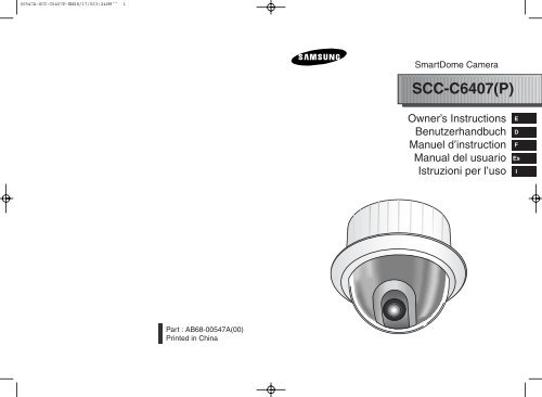
SmartDome Camera<br />
<strong>SCC</strong>-<strong>C6407</strong>(P)<br />
Owner’s Instructions<br />
Benutzerhandbuch<br />
Manuel d’instruction<br />
Manual del usuario<br />
Istruzioni per l’uso<br />
E<br />
D<br />
F<br />
Es<br />
I<br />
Part : AB68-00547A(00)<br />
Printed in China
00547A-<strong>SCC</strong>-<strong>C6407</strong>P-ENG 8/17/06 3:24 PM ˘` 3<br />
Important Safety Instructions<br />
Safety Precautions<br />
1. Read these instructions.<br />
2. Keep these instructions.<br />
3. Heed all warnings.<br />
4. Follow all instructions.<br />
5. Do not use this apparatus near water.<br />
6. Clean only with dry cloth.<br />
7. Do not block any ventilation openings, Install in accordance with the<br />
manufacturer's instructions.<br />
8. Do not install near any heat sources such as radiators, heat registers, or<br />
other apparatus (including amplifiers) that produce heat.<br />
9. Do not defeat the safety purpose of the polarized or grounding- type plug.<br />
A polarized plug has two blades with one wider than the other.<br />
A grounding type plug has two blades and a third grounding prong.<br />
The wide blade or the third prong are provided for your safety. If the<br />
provided plug does not fit into your outlet, consult an electrician for<br />
replacement of the obsolete outlet.<br />
10. Protect the power cord from being walked on or pinched particularly at<br />
plugs, convenience receptacles, and the point where they exit from the<br />
apparatus.<br />
11. Only use attachments/accessories specified by the manufacturer.<br />
12. Use only with cart, stand, tripod, bracket, or table specified by the<br />
manufacturer, or sold with the apparatus.<br />
13. Unplug this apparatus. When a cart is used, use caution when moving the<br />
cart/apparatus combination to avoid injury from tip-over.<br />
14. Refer all servicing to qualified service personnel. Servicing is required<br />
when the apparatus has been damaged in any way, such as power-supply<br />
cord or plug is damaged, liquid has been spilled or objects have fallen into<br />
the apparatus the apparatus has been exposed to rain or moisture, does<br />
not operate normally, or has been dropped.<br />
The purpose of this information is to ensure proper use of this product to<br />
prevent danger or damage to property. Please be sure to observe all<br />
precautions.<br />
* The precautions are divided into "Warnings" and "Cautions" as<br />
distinguished below:<br />
Warning: Ignoring this warning may result in death or serious injury.<br />
Caution: Ignoring this caution may result in injury or damage to property.<br />
Warning instructions alert you to<br />
a potential risk of death<br />
or serious injury.<br />
Warning<br />
Caution instructions alert you to the<br />
potential risk of injury or<br />
damage to property.<br />
1. Be sure to use only the standard adapter which is specified in the<br />
specification sheet.<br />
Using any other adapter could cause fire, electrical shock, or damage to<br />
the product.<br />
2. When connecting the power supply and signal wires, check the external<br />
connection terminals before connecting them. Connect the alarm signal<br />
wires to the alarm terminals, the AC adapter to the AC power input<br />
receptacle, and the DC adapter to the DC power input, making sure that<br />
the correct polarity is observed.<br />
(Connecting the power supply incorrectly may cause fire, electrical shock,<br />
or damage to the product.)<br />
3. Do not connect multiple cameras to a single adapter.<br />
(Exceeding the capacity may cause abnormal heat generation or fire.)<br />
(A falling camera may cause personal injury.)<br />
4. Securely plug the power cord into the power receptacle.<br />
(Insecure connection may cause fire.)<br />
5. When installing the camera on a wall or ceiling, fasten it securely and<br />
firmly. (A falling camera may cause personal injury.)<br />
E
00547A-<strong>SCC</strong>-<strong>C6407</strong>P-ENG 8/17/06 3:24 PM ˘` 5<br />
6. Do not place conductive objects (e.g., screwdrivers, coins, and metal<br />
things) or containers filled with water on top of the camera. (Doing so may<br />
cause personal injury due to fire, electrical shock, or falling objects.)<br />
7. Do not install the unit in humid, dusty, or sooty locations.<br />
(Doing so may cause fire or electrical shock.)<br />
8. If any unusual smells or smoke come from the unit, stop using the product.<br />
In such case, immediately disconnect the power source and contact the<br />
service center. (Continued use in such a condition may cause fire or<br />
electrical shock.)<br />
9. If this product fails to operate normally, contact the store of purchase or<br />
your nearest service center. Never disassemble or modify this product in<br />
any way. (SAMSUNG is not liable for problems caused by unauthorized<br />
modifications or attempted repair.)<br />
10. When cleaning, do not spray water directly onto parts of the product.<br />
(Doing so may cause fire or electrical shock.)<br />
Wipe the surface with a dry cloth. Never use detergents or chemical<br />
cleaners on the product, as this may result in discoloration of surface or<br />
cause damage to the finish.<br />
FCC STATEMENT<br />
This device complies with Part 15 of the FCC Rules. Operation is subject to<br />
the following two conditions:<br />
(1) This device may not cause harmful interference, and<br />
(2) This device must accept any interference received, including interference<br />
that may cause undesired operation.<br />
Note: This equipment has been tested and found to comply with the limits for<br />
a Class A digital device, pursuant to part 15 of the FCC Rules. These<br />
limits are designed to provide reasonable protection against harmful<br />
interference when the equipment is operated in a commercial<br />
environment. This equipment generates, uses, and can radiate radio<br />
frequency energy and, if not installed and used in accordance with the<br />
instruction manual, may cause harmful interference to radio<br />
communications. Operation of this equipment in a residential area is<br />
likely to cause harmful interference in which case the user will be<br />
required to correct the interference at his own expense.<br />
E<br />
Caution<br />
1. Do not drop objects on the product or apply strong shock to it. Keep away<br />
from a location subject to excessive vibration or magnetic interference.<br />
2. Do not install in a location subject to high temperature (over 122°F), low<br />
temperature (below 14°F), or high humidity.<br />
(Doing so may cause fire or electrical shock.)<br />
3. Avoid a location which is exposed to direct sunlight, or near heat sources<br />
such as heaters or radiators.<br />
(Neglecting to do so may result in a risk of fire.)<br />
4. If you want to relocate the already installed product, be sure to turn off the<br />
power and then move or reinstall it.<br />
5. Install in a well-ventilated location.<br />
6. Remove the power plug from the outlet when there is a lightning storm.<br />
(Neglecting to do so may cause fire or damage to the product.)
00547A-<strong>SCC</strong>-<strong>C6407</strong>P-ENG 8/17/06 3:24 PM ˘` 1-1<br />
Before Usage<br />
This is a basic instruction manual for the <strong>SCC</strong>-<strong>C6407</strong>(P) user.<br />
It contains all the instructions needed to use the <strong>SCC</strong>-<strong>C6407</strong>(P)<br />
from a simple introduction of the control locations and functions of<br />
the <strong>SCC</strong>-<strong>C6407</strong>(P) to installation methods in the set up menu.<br />
We recommend all users of the <strong>SCC</strong>-<strong>C6407</strong>(P) from the<br />
advanced user who has used similar cameras before to the<br />
general user to read the instruction manual before using.<br />
E<br />
The most frequently used feature in the <strong>SCC</strong>-<strong>C6407</strong>(P) would be<br />
the <strong>SCC</strong>-<strong>C6407</strong>(P) Setup Menu.<br />
The <strong>SCC</strong>-<strong>C6407</strong>(P) Setup Menu is explained in detailed in<br />
"Chapter 3 Setup Menu Overview".<br />
The instructional manual is best used when read from beginning<br />
to end, but for users wanting to read only the part they need here<br />
are the Chapter summaries.<br />
"Chapter 1 <strong>SCC</strong>-<strong>C6407</strong>(P) Overview" includes a brief<br />
introduction of the <strong>SCC</strong>-<strong>C6407</strong>(P), part names and functions, and<br />
Switch Settings.<br />
"Chapter 2 <strong>SCC</strong>-<strong>C6407</strong>(P) Installation" explains the installation<br />
procedures of the <strong>SCC</strong>-<strong>C6407</strong>(P) and provides preparation and<br />
installation environment requirements.<br />
"Chapter 3 Setup Menu Overview" presents the structure of the<br />
Setup menu for the <strong>SCC</strong>-<strong>C6407</strong>(P) including a detailed<br />
explanation of the functions performed in each submenu.<br />
"Appendix <strong>SCC</strong>-<strong>C6407</strong>(P) Product Specifications" contains<br />
product specifications of the <strong>SCC</strong>-<strong>C6407</strong>(P) in itemized<br />
categories.<br />
1-1<br />
1-2
00547A-<strong>SCC</strong>-<strong>C6407</strong>P-ENG 8/17/06 3:24 PM ˘` 1-3<br />
Table of contents<br />
1-3<br />
Before Usage...............................................................................................1-1<br />
Chapter 1 <strong>SCC</strong>-<strong>C6407</strong>(P) Overview ............................................................1-5<br />
<strong>SCC</strong>-<strong>C6407</strong>(P) Introduction ...........................................................1-6<br />
Locations of Control .......................................................................1-7<br />
FRONT...........................................................................................1-7<br />
BACK .............................................................................................1-8<br />
ADAPTER CONNECTION.............................................................1-9<br />
INITIAL SETTING ..........................................................................1-10<br />
Setting RS-422A/RS-485 termination ............................................1-11<br />
Chapter 2 <strong>SCC</strong>-<strong>C6407</strong>(P) Installation .........................................................2-1<br />
Before Installing .............................................................................2-2<br />
Preparing the Cables .....................................................................2-3<br />
Cable Connection ..........................................................................2-4<br />
Installing <strong>SCC</strong>-<strong>C6407</strong>(P)................................................................2-5<br />
Installing the Camera .....................................................................2-8<br />
Chapter 3 Setup Menu Overview ................................................................3-1<br />
Structure of the Setup Menu ..........................................................3-2<br />
1. CAMERA SET ...........................................................................3-4<br />
- CAMERA ID.............................................................................3-4<br />
- V-SYNC ...................................................................................3-5<br />
- COLOR/BW .............................................................................3-6<br />
- MOTION DET ..........................................................................3-7<br />
- ZOOM SPEED.........................................................................3-8<br />
- DIGITAL ZOOM .......................................................................3-9<br />
- DISPLAY ZOOM......................................................................3-9<br />
- DISPLAY P/T ...........................................................................3-9<br />
- EXIT.........................................................................................3-10<br />
2. VIDEO SET ...............................................................................3-10<br />
- IRIS..........................................................................................3-10<br />
- ALC.......................................................................................3-10<br />
- BLC.....................................................................................3-10<br />
- WDR .....................................................................................3-11<br />
- MANU ...................................................................................3-11<br />
- SHUTTER................................................................................3-12<br />
- FLICKERLESS ......................................................................3-12<br />
- AGC .........................................................................................3-13<br />
- MOTION ..................................................................................3-13<br />
- WHITE BAL .............................................................................3-14<br />
- DIS...........................................................................................3-15<br />
- FOCUS MODE ........................................................................3-16<br />
- SPECIAL..................................................................................3-16<br />
- EXIT.........................................................................................3-16<br />
3. PRESET.....................................................................................3-17<br />
- POSITION SET........................................................................3-18<br />
- PRESET ID..............................................................................3-18<br />
- VIDEO SET..............................................................................3-18<br />
- PRESET SPEED .....................................................................3-18<br />
- DWELL TIME...........................................................................3-18<br />
- IMAGE HOLD ..........................................................................3-18<br />
- EXIT.........................................................................................3-18<br />
4. ZONE SET ..................................................................................3-19<br />
- PRIVACY ZONE .......................................................................3-19<br />
- STYLE....................................................................................3-19<br />
- BLANK ALL ABOVE...............................................................3-20<br />
- BLANK ALL BELOW ..............................................................3-20<br />
- PRYVACY ZONE MAP ..........................................................3-20<br />
- SET ZONE AREA ...............................................................3-21<br />
- SET ZOOM .........................................................................3-22<br />
- REVERSE ...........................................................................3-22<br />
- EXIT ....................................................................................3-22<br />
- ZONE DIR SET/ZONE AREA SET ...........................................3-22<br />
- ZONE DIR SET .........................................................................3-23<br />
- ZONE AREA .............................................................................3-23<br />
- LOCATION.............................................................................3-24<br />
- ZONE ID SET.........................................................................3-24<br />
- ZONE ENABLE ......................................................................3-24<br />
5. AUTO SET ..................................................................................3-25<br />
- AUTO PAN................................................................................3-25<br />
- POSITION SET ......................................................................3-25<br />
- DIRECTION ...........................................................................3-26<br />
- ENDLESS ..............................................................................3-26<br />
- SPEED ...................................................................................3-26<br />
- DWELL TIME .........................................................................3-26<br />
- PATTERN .................................................................................3-26<br />
- SCAN ........................................................................................3-27<br />
- AUTO PLAY ..............................................................................3-28<br />
- AUTO RETURN .....................................................................3-28<br />
- AUTO PLAY ...........................................................................3-28<br />
- PLAY NUMBER .....................................................................3-28<br />
6. ALARM SET ................................................................................3-29<br />
- ALARM PRIORITY SET............................................................3-29<br />
- ALARM IN SET .........................................................................3-29<br />
- ALARM OUT SET .....................................................................3-29<br />
- AUTO SET ................................................................................3-30<br />
- AUX OUT CONTROL................................................................3-30<br />
7. OTHER SET................................................................................3-30<br />
- PROPORTINAL P/T..................................................................3-30<br />
- TURBO P/T ...............................................................................3-31<br />
- AUTO CAL ................................................................................3-31<br />
- D-FLIP.......................................................................................3-31<br />
- CAM RESET .............................................................................3-31<br />
- LANGUAGE ..............................................................................3-31<br />
- PASSWORD .............................................................................3-31<br />
8. SYSTEM INFO ............................................................................3-32<br />
9. SHORT KEYS .............................................................................3-33<br />
Product specifications ............................................................................3-35<br />
1-4<br />
E
00547A-<strong>SCC</strong>-<strong>C6407</strong>P-ENG 8/17/06 3:24 PM ˘` 1-5<br />
Chapter 1 <strong>SCC</strong>-<strong>C6407</strong>(P) Overview<br />
In this chapter we will briefly introduce the <strong>SCC</strong>-<strong>C6407</strong>(P) and<br />
show main functions, locations of control and Switch Setting.<br />
<strong>SCC</strong>-<strong>C6407</strong>(P) Introduction<br />
<strong>SCC</strong>-<strong>C6407</strong>(P) is a zoom lens built in smart dome camera which<br />
provides you with the best monitoring function in connection with<br />
CCTV at banks or companies.<br />
The <strong>SCC</strong>-<strong>C6407</strong>(P) is a high quality surveillance camera using x32<br />
zoom lens and digital zoom IC, it can catch clear images up to 320<br />
times.<br />
<strong>SCC</strong>-<strong>C6407</strong>(P) has a variety of functions such as;<br />
- WDR to cover the full screen irregardless of its brightness,<br />
- DAY/NIGHT to improve the sensitivity by automatic conversion<br />
into the black and white mode at night or in the environment with<br />
low illumination,<br />
- White Balance to control the brightness to the illumination,<br />
- Backlight Compensation under spotlight or utmost bright<br />
illumination,<br />
- Auto Focus to automatically adjust the focus to the subject<br />
movement,<br />
- Privacy zone to hide a specific area for personal privacy, and,<br />
- PAN/TILT for precise control at high speed.<br />
E<br />
The <strong>SCC</strong>-<strong>C6407</strong>(P) uses an Alarm function for alert situations and<br />
moving camera in the direction you want, ZOOM-IN and<br />
ZOOM-OUT functions can be remote controlled.<br />
1-5<br />
1-6
00547A-<strong>SCC</strong>-<strong>C6407</strong>P-ENG 8/17/06 3:24 PM ˘` 1-7<br />
Locations of Control<br />
FRONT<br />
BACK<br />
E<br />
1-7<br />
1-8
00547A-<strong>SCC</strong>-<strong>C6407</strong>P-ENG 8/17/06 3:24 PM ˘` 1-9<br />
ADAPTER CONNECTION<br />
INITIAL SETTING<br />
<strong>SCC</strong>-<strong>C6407</strong>(P) Adapter BOARD<br />
CAMERA ADDRESS SETUP<br />
Use SW701, SW702, or 703 for Camera Address setup. You may allocate<br />
up to 255 addresses by using SW701 to set the 3rd digit, SW702 the 2nd<br />
digit, and SW703 the 1st digit.<br />
EX) In case of Camera Address 1, see the following figure for setup.<br />
E<br />
SW701 SW702 SW703<br />
Setting communication Protocol<br />
Use number 1~4 PIN of SW704 to set communication Protocol.<br />
PIN<br />
Comp<br />
PIN1 PIN2 PIN3 PIN4<br />
A OFF OFF OFF OFF<br />
B ON OFF OFF OFF<br />
C OFF ON OFF OFF<br />
D ON ON OFF OFF<br />
E OFF OFF ON OFF<br />
F ON OFF ON OFF<br />
G OFF ON ON OFF<br />
H ON ON ON OFF<br />
I OFF OFF OFF ON<br />
J ON OFF OFF ON<br />
K OFF ON OFF ON<br />
L ON ON OFF ON<br />
M OFF OFF ON ON<br />
N ON OFF ON ON<br />
O OFF ON ON ON<br />
P ON ON ON ON<br />
A : SAMSUNG HALF<br />
B : SAMSUNG FULL<br />
SEE INSTRUCTION MANUAL<br />
ON 1 2 3 4 5 6 7 8<br />
(x100) (x10) (x1)<br />
SW704<br />
SW701 SW702 SW703<br />
(BOTTOM VIEW)<br />
Baud Rate Setting<br />
Use PIN 5 and 6 of SW704.<br />
1 2 3 4 5 6 7 8<br />
ON<br />
1-9<br />
OFF<br />
SW 704<br />
BAUD RATE<br />
PIN 5<br />
4800 BPS<br />
ON<br />
9600 BPS<br />
OFF<br />
19200 BPS<br />
ON<br />
38400 BPS<br />
OFF<br />
The factory default setting is set to 9600BPS.<br />
PIN 6<br />
ON<br />
ON<br />
OFF<br />
OFF<br />
1-10
00547A-<strong>SCC</strong>-<strong>C6407</strong>P-ENG 8/17/06 3:24 PM ˘` 1-11<br />
Setting RS-422A/RS-485 termination<br />
Chapter 2 <strong>SCC</strong>-<strong>C6407</strong>(P) Installation<br />
As it is shown in the structure map, when Controller and RS-422A/RS-<br />
485 is connected it should be terminated according to the Cable feature<br />
of impedance on the each end of the transmitting line to transfer the<br />
signals in long distance by controlling the reflection of the signals to the<br />
lowest.<br />
Division<br />
n < 32<br />
Termination<br />
SW1-ON<br />
In this chapter, we will check the contents of the package before<br />
installing the <strong>SCC</strong>-<strong>C6407</strong>(P), and prepare a power adapter suitable<br />
for the power supply system.<br />
(Power Consumption: 22W; Voltage: AC24V, 1.5A)<br />
Then, we will install the <strong>SCC</strong>-<strong>C6407</strong>(P) and connect the cables.<br />
E<br />
<br />
Termination: using numbers 1 and 2 PIN, turn to ON and it will be terminated.<br />
n < 32<br />
Division<br />
Division<br />
SW1-ON<br />
SW2-ON<br />
<br />
❈ A communication error may occur if you connect multiple cameras<br />
that are assigned the same address in the network.<br />
1-11<br />
2-1
00547A-<strong>SCC</strong>-<strong>C6407</strong>P-ENG 8/17/06 3:24 PM ˘` 2-2<br />
Before Installing<br />
Preparing the Cables<br />
Checking Package Contents<br />
Please check that all components listed below are included in the package:<br />
To install and use the <strong>SCC</strong>-<strong>C6407</strong>(P), the following cables should be<br />
prepared.<br />
Power Adapter Cable<br />
The cable that plugs into the <strong>SCC</strong>-<strong>C6407</strong>(P) power input receptacle has<br />
the rated voltage of AC24V, 1.5A.<br />
Check the rated voltage before using the cable.<br />
E<br />
<strong>SCC</strong>-<strong>C6407</strong>(P)<br />
Bracket anchor<br />
Screws<br />
Owner’s<br />
Instructions<br />
Cover Body<br />
Video Cable<br />
The <strong>SCC</strong>-<strong>C6407</strong>(P)'s cable is a BNC Cable for connecting the videooutput<br />
terminal to the video-input terminal of the monitor.<br />
Camera Holder<br />
Adapter Board<br />
2-2<br />
2-3
00547A-<strong>SCC</strong>-<strong>C6407</strong>P-ENG 8/17/06 3:24 PM ˘` 2-4<br />
Cable Connection<br />
Installing <strong>SCC</strong>-<strong>C6407</strong>(P)<br />
1. First, connect one end of the<br />
BNC video cable connector to<br />
the Video Output Terminal<br />
(VIDEO OUT)<br />
2. Then, connect the other end of<br />
the connector to the Video Input<br />
Terminal of the monitor.<br />
Installation Precautions<br />
1) Make sure that the installation site can sufficiently support a minimum of<br />
four times the net weight of the <strong>SCC</strong>-<strong>C6407</strong>(P) SmartDome Camera<br />
and other accessories.<br />
2) Install in an area where the space above the ceiling board is over 18 cm<br />
(7 in.) high.<br />
3) Use the supplied screws to fasten the camera to the bracket assembly.<br />
4) Keep persons away from the installation area, as there is a risk of falling<br />
objects.<br />
Also, move valuables to a safe location before installation.<br />
E<br />
3. Now connect the Power Adapter<br />
Cable. Use a driver to screw<br />
one part of the two lines of<br />
Power Adapter to Power Input<br />
Terminal of the <strong>SCC</strong>-<strong>C6407</strong>(P).<br />
Separately Sold Products for Installation<br />
Depending on the installation site, it may be convenient to use one of the<br />
following products.<br />
1) CEILING MOUNT BRACKET<br />
(SBR-100DCM)<br />
This bracket is used for installing<br />
the SmartDome CAMERA in the<br />
plenum above the drop ceiling.<br />
4. Adjust the switch on the Power Adapter to the proper voltage.<br />
Then, connect the Power Adapter's plug to the Power Connector.<br />
5. Connect the Remote Control<br />
Terminal of the<br />
<strong>SCC</strong>-<strong>C6407</strong>(P)<br />
and the external Controller.<br />
2) WALL MOUNT ADAPTOR<br />
(SADT-100WM)<br />
This adaptor is used for installing the<br />
indoor housing or the outdoor<br />
housing for the SmartDome Camera<br />
on a wall.<br />
Controller<br />
Adapter BOARD<br />
2-4<br />
2-5
00547A-<strong>SCC</strong>-<strong>C6407</strong>P-ENG 8/17/06 3:24 PM ˘` 2-6<br />
3) INDOOR HOUSING (SHG-120)<br />
This housing is used for installing the SmartDome Camera to an indoor<br />
wall or a ceiling.<br />
5) CEILING MOUNT ADAPTOR (SADT-100CM)<br />
This adaptor is used for installing the indoor housing or the outdoor<br />
housing for the SmartDome Camera to a concrete ceiling.<br />
E<br />
4) OUTDOOR HOUSING (SHG-220)<br />
This housing is used for installing the SmartDome Camera to an<br />
outdoor wall or a ceiling.<br />
6) POLE MOUNT ADAPTOR (SADT-100PM)<br />
This adaptor is used for installing the WALL MOUNT ADAPTOR<br />
(SADT-100WM) to a pole that is over 8 cm (2.76 in.) in diameter.<br />
❈ To install and use OUTDOOR HOUSING, remove the Clear Case<br />
from the Camera body before installation.<br />
2-6<br />
2-7
00547A-<strong>SCC</strong>-<strong>C6407</strong>P-ENG 8/17/06 3:24 PM ˘` 2-8<br />
Installing the Camera<br />
1. [Figure 1] Install the structure on the<br />
ceiling.<br />
(Refer to Installation reference<br />
for the Length of the structure)<br />
* Built in by the builder of the structure<br />
5. [Figure 5] Match the<br />
BRKT-ANCHOR and CAMERA<br />
ADAPTER and use 4screws<br />
(PH M4 x 8) to assemble them.<br />
[Figure 5]<br />
6. Pull the safety wire from the case<br />
body, and assembly it to the<br />
camera holder.<br />
[Figure 6]<br />
E<br />
[Figure 1]<br />
Length of<br />
ceiling Hole<br />
2. Make a hole in the ceiling where the camera will be installed.<br />
(The hole should be about ø185)<br />
3. [Figure 2] Assemble the<br />
BRKT-ANCHOR on the ceiling<br />
and screw the 4 bolts in.<br />
[Figure 2]<br />
4. [Figure 3,4] Connect the various cables to the CAMERA ADAPTER.<br />
(See page 2-4)<br />
7. [Figure 7] Match the 3 holes on the<br />
back of the CAMERA and the<br />
CONNECTOR and turn it left about<br />
15 degrees.<br />
(Check the sound of LOCKING<br />
and that the LEVER-LOCKING<br />
is in place)<br />
* Use the screws (BH M3 x L8) to<br />
connect the CAMERA and the<br />
ADAPTER so they don't move.<br />
[Figure 7]<br />
8. [Figure 8] Assemble the<br />
COVER-BODY onto the DOME.<br />
[Figure 8]<br />
[Figure 3]<br />
[Figure 4]<br />
2-8<br />
2-9
00547A-<strong>SCC</strong>-<strong>C6407</strong>P-ENG 8/17/06 3:24 PM ˘` 3-1<br />
Structure of the Setup Menu<br />
Chapter 3 Setup Menu Overview<br />
In this chapter, we will look over the Setup Menu of the<br />
<strong>SCC</strong>-<strong>C6407</strong>(P), First we'll look over the overall structure of the<br />
Setup Menu, and then we'll look at the functions of each menu.<br />
CAMERA SET CAMERA ID ON.../OFF<br />
V-SYNC<br />
INT/LINE...<br />
COLOR/BW COLOR.../BW.../AUTO...<br />
MOTION DET ON.../OFF<br />
ZOOM SPEED 1/2/3/4<br />
DIGITAL ZOOM OFF/X2~X10<br />
DISPLAY ZOOM OFF/ON<br />
DISPLAY P/T OFF/ON<br />
EXIT<br />
QUIT/SAVE/PRESET<br />
VIDEO SET IRIS ALC.../WDR.../MANU...<br />
SHUTTER OFF/1/100(1/120)~10K/AUTOX2...~X160...<br />
AGC/MOTION OFF/LOW/HIGH (AGC)<br />
S.SLOW/SLOW/NORM/FAST/F.FAST(MOTION)<br />
WHITE BAL ATW1/ATW2/AWC/MANU...<br />
DIS<br />
ON/OFF<br />
FOCUS MODE ONEAF/MF<br />
SPECIAL ...<br />
REVERSE OFF/H/V/H/V<br />
Y-LEVEL (0)l---<br />
C-LEVEL (0)l---<br />
DETAIL (0)l---<br />
RET<br />
EXIT<br />
QUIT/SAVE/PRESET<br />
PRESET POSITION SET ...<br />
PRESET ID ON.../OFF<br />
VIDEO SET ON.../OFF<br />
PRESET SPEED 1~8<br />
DWELL TIME 1~60S<br />
IMAGE HOLD ON/OFF<br />
EXIT<br />
QUIT/SAVE/DEL<br />
ZONE SET PRIVACY ZONE ...<br />
ZONE DIR SET OFF/ON...<br />
ZONE AREA SET OFF/ON...<br />
EXIT<br />
QUIT/SAVE<br />
AUTO SET AUTO PAN 1.../2.../3.../4...<br />
PATTERN 1.../2.../3...<br />
SCAN 1.../2.../3.../4...<br />
AUTO PLAY ...<br />
RET<br />
E<br />
3-1<br />
3-2
00547A-<strong>SCC</strong>-<strong>C6407</strong>P-ENG 8/17/06 3:24 PM ˘` 3-3<br />
ALARM SET ALARM PRIORITY SET ALARM1~8 1~8<br />
EXIT QUIT/SAVE<br />
ALARM IN SET ALARM1~8 NO/NC/OFF<br />
EXIT<br />
QUIT/SAVE<br />
ALARM OUT SET ALARM1~8 1~3<br />
MOTION 1~3<br />
EXIT QUIT/SAVE<br />
AUTO SET ALARM1~8 OFF/PATTERN1~3/HALF1~2/FULL/SCAN1~4<br />
MOTION OFF/PATTERN1~3/HALF1~2/FULL/SCAN1~4<br />
EXIT QUIT/SAVE<br />
AUX OUT CONTROL<br />
RET<br />
OUT1 ON/OFF<br />
OUT2 ON/OFF<br />
OUT3 ON/OFF<br />
EXIT QUIT/SAVE<br />
OTHER SET PROPOTIONAL P/T ON/OFF<br />
TURBO P/T<br />
ON/OFF<br />
AUTO CAL<br />
OFF/6HOUR/12HOUR/18HOUR/24HOUR<br />
D-FLIP<br />
ON/OFF<br />
CAM RESET ...<br />
LANGUAGE<br />
ENGLISH/FRANÇAIS/DEUTSCH/ESPAÑOL/ITALIANO<br />
PASSWORD<br />
ON.../OFF<br />
EXIT<br />
QUIT/SAVE<br />
SYSTEM INFO<br />
The diagram shown above illustrates the overall structure of the Setup Menu.<br />
In this section, a description of the Setup menu features will enable users of the<br />
<strong>SCC</strong>-<strong>C6407</strong>(P) to tailor it to their personal needs.<br />
❈ If the power is turned off after PRESET, AUTO PAN, SCAN,<br />
PATTERN function is activated and no other control is made, camera<br />
will do the same function after the power is turned on.<br />
❈ Menu setting is available only when tilt position is under 90°.<br />
When tilt position is over 90° and menu-on command is received,<br />
pan will automatically rotate 180° and tilt will be move to the<br />
corresponding position.<br />
Use the controller to press the MENU selection key and the following<br />
screen will be displayed.<br />
* * MAIN MENU * *<br />
CAMERA SET...<br />
VIDEO SET...<br />
PRESET ...<br />
ZONE SET...<br />
AUTO SET...<br />
ALARM SET...<br />
OTHER SET...<br />
SYSTEM INFO...<br />
➀ PASSWORD<br />
UNDEFINED<br />
In case of ➀, use UP/DOWN/LEFT/RIGHT/[ENTER] key for MENU<br />
setup. In case of ➁, type in the 4 digit password first. If correct, the<br />
MENU selection screen like ➀ will be displayed and you will be able to<br />
set up MENU by pressing UP/DOWN/LEFT/RIGHT/[ENTER] key.<br />
1. CAMERA SET MENU<br />
0 1 2 3 4<br />
5 6 7 8 9<br />
✽ ✽ ✽ ✽<br />
➁ PASSWORD<br />
DEFINED<br />
CAMERA ID<br />
The CAMERA ID menu assigns an ID to the <strong>SCC</strong>-<strong>C6407</strong>(P) to be displayed<br />
on the connected monitor.On the CAMERA SET menu screen, select<br />
CAMERA ID to ON and press [Enter]. You will see the sub screen for<br />
deciding on the ID of the <strong>SCC</strong>-<strong>C6407</strong>(P). The Camera ID can have up to<br />
20 alphanumeric characters, along with several special characters.<br />
The assigned camera ID may be positioned to any desired location on the<br />
screen by using the LOCATION submenu.<br />
E<br />
3-3 3-4
00547A-<strong>SCC</strong>-<strong>C6407</strong>P-ENG 8/17/06 3:24 PM ˘` 3-5<br />
(CAMERA SET)<br />
CAMERA ID ON...<br />
V-SYNC INT<br />
COLOR/BW COLOR...<br />
MOTION DET OFF<br />
ZOOM SPEED 3<br />
DIGITAL ZOOM OFF<br />
DISPLAY ZOOM OFF<br />
DISPLAY P/T OFF<br />
EXIT<br />
QUIT<br />
(CAMERA SET)<br />
CAMERA ID OFF<br />
V-SYNC LINE...<br />
COLOR/BW COLOR...<br />
MOTION DET OFF<br />
ZOOM SPEED 3<br />
DIGITAL ZOOM OFF<br />
DISPLAY ZOOM OFF<br />
DISPLAY P/T OFF<br />
EXIT<br />
QUIT<br />
➜<br />
Press<br />
[Enter]<br />
* " ... " Means there are Sub Menus.<br />
➜<br />
Press<br />
[Enter]<br />
(CAMERA ID)<br />
A B C D E F G H I J K L<br />
M N O PQ R S T U V W X<br />
Y Z 0 1 2 3 4 5 6 7 8 9<br />
: ! - + ✽ ( ) /<br />
SP ï î SP<br />
LOCATION...<br />
RET<br />
WDR.DOME.CAMERA.....<br />
V-SYNC<br />
In the V-SYNC menu, vertical synchronization can be selected. The<br />
vertical synchronization signal supported by the <strong>SCC</strong>-<strong>C6407</strong>(P) is the INT<br />
mode made by clock inside the <strong>SCC</strong>-<strong>C6407</strong>(P) and LINE mode adjusting<br />
vertical synchronization to the exterior power frequency.<br />
Select LINE and press [Enter]. You will see the LINE LOCK submenu<br />
where you can adjust the phase of the LINE LOCK.<br />
You can use the PHASE menu of the LINE LOCK submenu to assign as<br />
much PHASE as you want.<br />
(LL-PHASE)<br />
PHASE<br />
RET<br />
(-106)I--------<br />
COLOR/BW<br />
In the COLOR/BW menu, you can switch ON or OFF the IR (infrared) Filter.<br />
In a poor illumination environment, the IR filter is turned off in the BW mode the its<br />
sensitivity increases as high as a black and white camera. On the other hand, the<br />
IR filter is turned on and the sensitivity decreases in the COLOR mode.<br />
COLOR : The IR Filter is ON and the screen is normal. You can press the<br />
[Enter] key to set the COLOR GAIN LEVEL. And when the AGC<br />
function is on, you can set the AGC COLOER LEVEL.<br />
(CAMERA SET)<br />
CAMERA ID OFF<br />
V-SYNC INT<br />
COLOR/BW COLOR …<br />
MOTION OFF<br />
ZOOM SPEED 3<br />
DIGITAL ZOOM OFF<br />
DISPLAY ZOOM OFF<br />
DISPLAY P/T OFF<br />
EXIT<br />
QUIT<br />
BW<br />
AUTO<br />
: The IR Filter is OFF and the screen is black and white.<br />
(Sensitivity to low light is increased to a level comparable to a black<br />
and white camera.)<br />
Select BW and press [ENTER] and the additional menu to select<br />
BURST ON/OFF will appear.<br />
: Select to automatically switch between the COLOR mode and BW<br />
mode depending on the amount of light. In low light conditions, the<br />
IR Filter is turned OFF and the sensitivity to low light is increased<br />
by switching to the BW mode, but in bright light conditions, the IR<br />
Filter is turned ON and the sensitivity is decreased by switching to<br />
the COLOR mode.<br />
Select AUTO and press [ENTER] and the additional menu to select<br />
BW LEVEL and DURATION will appear.<br />
- BURST ON : The color burst signal is output together with black and white<br />
composite video signal.<br />
- BURST OFF : The color burst signal is not output.<br />
- LEVEL : You can set the brightness level that changes from COLOR mode<br />
to BW mode in 3 steps : LOW, MEDIUM, and HIGH.<br />
- DURATION : Set the HOLDING time for switching between COLOR and BW<br />
mode depending the changes in the amount of light. You can set<br />
the HOLDING time to 10sec (S), 30sec, 60sec, or 300sec( L).<br />
➜<br />
Press<br />
[Enter]<br />
(COLOR)<br />
GAIN<br />
AGC COLOR<br />
RET<br />
(0)I--------<br />
(0)----I----<br />
E<br />
3-5 3-6
00547A-<strong>SCC</strong>-<strong>C6407</strong>P-ENG 8/17/06 3:24 PM ˘` 3-7<br />
❈ In AUTO mode, AGC will be displayed as “---“. You can’t adjust the<br />
settings manually.<br />
(CAMERA SET)<br />
CAMERA ID OFF<br />
V-SYNC INT<br />
COLOR/BW AUTO...<br />
MOTION DET OFF<br />
ZOOM SPEED 3<br />
DIGITAL ZOOM OFF<br />
DISPLAY ZOOM OFF<br />
DISPLAY P/T OFF<br />
EXIT<br />
QUIT<br />
➜<br />
Press<br />
[Enter]<br />
(AUTO)<br />
BURST<br />
LEVEL<br />
DURATION<br />
RET<br />
ON<br />
LOW<br />
S --|---- L<br />
Caution : If you use an infrared light source while in AUTO mode, AUTO<br />
switching malfunction and camera AF malfunction may occur.<br />
Select ON and press [ENTER] and the MOTION DET additional menu will<br />
appear. The AREA menu, selecting the screen area where the MOTION<br />
detection function will be applied may be selected by PRESET or USER.<br />
Set AREA to PRESET and the MOTION detection function will be applied to<br />
the factory default part.<br />
If you set the AREA menu to USER and press [ENTER], you may vary the<br />
area and position of the area where you want to apply the MOTION detection<br />
function by yourself. Press Left, Right, Up, or Down to select an area area.<br />
Press ENTER and then Left, Right, Up, or Down to select a position. Press<br />
ENTER again to move back to the upper menu.<br />
Use [ENTER] and Left, Right, Up, or Down to move and scale the MOTION<br />
detection area.<br />
Press [ENTER] again and you will escape the AREA setup menu.<br />
Use SENSITIVITY to set up the sensitivity of MOTION detection strength.<br />
The higher, the more sensitive.<br />
E<br />
MOTION DET<br />
In MOTION DET, you can set the Motion Detection function, Motion Detection<br />
Sensitivity, and the Area of Motion Detection. If the Motion Detection function<br />
is set, the movement of an intruder can be detected. When motion is detected,<br />
it sets off the Alarm signal of the Controller.<br />
(CAMERA SET)<br />
CAMERA ID OFF<br />
V-SYNC INT<br />
COLOR/BW COLOR...<br />
MOTION DET ON...<br />
ZOOM SPEED 3<br />
DIGITAL ZOOM OFF<br />
DISPLAY ZOOM OFF<br />
DISPLAY P/T OFF<br />
EXIT<br />
QUIT<br />
➜<br />
Press<br />
[Enter]<br />
(MOTION DET)<br />
AREA<br />
SENSITIVITY<br />
RET<br />
PRESET...<br />
L ---|--- H<br />
AREA<br />
LOCATION<br />
➜<br />
Use the [Left,<br />
Right, Up, Down]<br />
Keys<br />
AREA<br />
LOCATION<br />
❈ After PAN/TILT/ZOOM/FOCUS/IRIS movement finishes, MOTION DET<br />
function will not work for about 5 seconds to stablize the chage of the<br />
screen.<br />
❈ MOTION detection function operates based on the brightness change<br />
within the setup region. Therefore, erroneous operation may occur<br />
depending on the brightness difference between the background and<br />
the object that is being taken, or the status of the area setup, etc.<br />
ZOOM SPEED<br />
In the ZOOM SPEED menu you can select the speed of the ZOOM Key<br />
(Tele/Wide).<br />
Use the [Left] or [Right] keys in the ZOOM SPEED menu to select<br />
the speed.<br />
1 : Slowest speed<br />
2 : Low speed<br />
3 : High speed<br />
4 : Fastest speed<br />
3-7<br />
3-8
00547A-<strong>SCC</strong>-<strong>C6407</strong>P-ENG 8/17/06 3:24 PM ˘` 3-9<br />
DIGITAL ZOOM<br />
You may set up the digital zoom magnification ratio in the DIGITAL ZOOM<br />
menu. The magnification ratio ranges from OFF to 10. If you set Digital<br />
Zoom of <strong>SCC</strong>-<strong>C6407</strong>(P) to max. 10 times, the mode will become the 32 time<br />
optical zoom and you will be able to enlarge a subject by max. 320 times.<br />
Use Left or Right to select a magnification ratio in the DIGITAL ZOOM menu.<br />
(CAMERA SET)<br />
CAMERA ID OFF<br />
V-SYNC INT<br />
COLOR/BW BW...<br />
MOTION DET OFF<br />
ZOOM SPEED 3<br />
DIGITAL ZOOM OFF<br />
DISPLAY ZOOM OFF<br />
DISPLAY P/T OFF<br />
EXIT<br />
QUIT<br />
(CAMERA SET)<br />
CAMERA ID OFF<br />
V-SYNC INT<br />
COLOR/BW BW...<br />
MOTION DET OFF<br />
ZOOM SPEED 3<br />
DIGITAL ZOOM X10<br />
DISPLAY ZOOM OFF<br />
DISPLAY P/T OFF<br />
EXIT<br />
QUIT<br />
DISPLAY ZOOM<br />
In DISPLAY ZOOM, you can display the ZOOM scale on the screen.<br />
(CAMERA SET)<br />
CAMERA ID OFF<br />
V-SYNC INT<br />
COLOR/BW COLOR...<br />
MOTION DET OFF<br />
ZOOM SPEED 4<br />
DIGITAL ZOOM OFF<br />
DISPLAY ZOOM ON<br />
DISPLAY P/T OFF<br />
EXIT<br />
SAVE<br />
X020<br />
❈ If no change on the ZOOM scale is made for 3 seconds, the<br />
information window will disappear.<br />
EXIT<br />
The EXIT menu is used to quit the CAMERA SET menu of the<br />
<strong>SCC</strong>-<strong>C6407</strong>(P) and return to the MAIN MENU.<br />
- QUIT : Ignores the changed information and restores the saved<br />
information.<br />
- SAVE : Saves the information of the setting condition of the menu.<br />
- PRESET: Ignores the changed information and restores the initial<br />
factory defaults of the menu.<br />
2. VIDEO SET MENU<br />
IRIS<br />
There is a function to automatically adjust IRIS to the incoming light level.<br />
Owing to this function, you may set up the brightness level yourself.<br />
The ALC(Auto Light Control) menu allows you for video output level setup.<br />
ALC<br />
Choose the ALC of the IRIS item and press [ENTER] and set he submenu<br />
to the Video Output level and BLC will be shown.The Video Output Level<br />
can be set in the level item using the [Left, Right] keys.<br />
BLC (Submenu of the ALC menu)<br />
If you use a general camera to photograph a subject under backlight or<br />
bright illumination, the subject will be shown dark on the monitor due to<br />
the backlight. BLC(Back Light Compensation) is used to prevent such a<br />
backlight problem to secure distinct images under bright illumination.<br />
Using the [Left, Right] keys, you can set up BOTTOM…, TOP…, LEFT…,<br />
RIGHT…, CENTER… 5 preset areas and the USER…function that can<br />
directly set the areas. For example, for the items in the BLC menu, you<br />
can confirm the preset BOTTOM area by pressing [ENTER] key in the<br />
BOTTOM… status.<br />
E<br />
DISPLAY P/T<br />
In DISPLAY P/T, you can display the position of Pan/Tilt on the screen.<br />
(CAMERA SET)<br />
CAMERA ID OFF<br />
V-SYNC INT<br />
COLOR/BW COLOR...<br />
MOTION DET OFF<br />
ZOOM SPEED 4<br />
DIGITAL ZOOM OFF<br />
DISPLAY ZOOM OFF<br />
DISPLAY P/T ON<br />
EXIT<br />
SAVE<br />
347/060<br />
❈ If no change on the Pan/Tilt position is made for 3 seconds, the<br />
information window will disappear.<br />
❈ It allows an error range of ±2°.<br />
(VIDEO SET)<br />
IRIS<br />
ALC...<br />
SHUTTER AUTO X2...<br />
MOTION NORM<br />
WHITE BAL ATW1<br />
DIS ---<br />
FOCUS MODE ONEAF<br />
SPECIAL ...<br />
EXIT<br />
(ALC)<br />
BLC<br />
LEVEL<br />
RET<br />
QUIT<br />
BOTTOM...<br />
(0)----I----<br />
➜<br />
Press<br />
[Enter]<br />
➜<br />
Press<br />
[Enter]<br />
(ALC)<br />
BLC<br />
LEVEL<br />
RET<br />
OFF<br />
(0)----I----<br />
3-9<br />
3-10
00547A-<strong>SCC</strong>-<strong>C6407</strong>P-ENG 8/17/06 3:24 PM ˘` 3-11<br />
For items in the BLC menu, the user can set the area and location of the<br />
BLC area by pressing [ENTER] key after put the cursor on USER… using<br />
the [Left, Right] key. For AREA items, you can use the [Up, Down, Left,<br />
Right] key to designate the AREA, and then press the [ENTER] key.<br />
You can set the location for areas using the [Up, Down, Left, Right] key in<br />
the LOCATION.<br />
(ALC)<br />
BLC<br />
USER...<br />
LEVEL (0) ----I----<br />
RET<br />
AREA<br />
LOCATION<br />
➜<br />
Press<br />
[Enter]<br />
➜<br />
Press<br />
[Enter]<br />
AREA<br />
LOCATION<br />
AREA<br />
LOCATION<br />
Use [Left, Right] key in the LEVEL menu to control the video output<br />
level(brightness).<br />
(VIDEO SET)<br />
IRIS<br />
MANU...<br />
SHUTTER OFF<br />
AGC<br />
OFF<br />
WHITE BAL ATW1<br />
DIS<br />
OFF<br />
FOCUS MODE ONEAF<br />
SPECIAL ...<br />
EXIT<br />
QUIT<br />
SHUTTER<br />
You may designate both the fast electronic shutter speed and low<br />
electronic shutter speed in the SHUTTER menu. The fast electronic<br />
shutter supports 7 shutter speeds from 1/100(1/120) to 1/10K second to<br />
be used for the bright and fast video image. The AUTO slow electronic<br />
shutter supports 10 shutter speeds from x2 to x160 and sets the shutter<br />
speed to be slow In order to make the image on the screen more distinct<br />
and brighter when you photograph under dark illumination. If you want to<br />
sense the light brightness to control the shutter speed to the brightness<br />
automatically, select the AUTO slow shutter.<br />
(VIDEO SET)<br />
Press the<br />
ENTER<br />
button.<br />
IRIS<br />
ALC...<br />
SHUTTER OFF<br />
AGC<br />
OFF<br />
WHITE BAL ATW1<br />
DIS<br />
OFF<br />
FOCUS MODE ONEAF<br />
SPECIAL ...<br />
EXIT<br />
QUIT<br />
(MANUAL)<br />
LEVEL (00) ----I----<br />
RET<br />
E<br />
WDR<br />
The WDR camera is a state-of-art technology to expand the screen profit,<br />
mostly effective when you photograph both indoor and outdoor. In short,<br />
this function provides you with the distinct reproduction of not only the<br />
indoor but also the outdoor. Press [ENTER] to set up the WDR leve.<br />
(VIDEO SET)<br />
IRIS<br />
WDR...<br />
SHUTTER OFF<br />
AGC<br />
OFF<br />
WHITE BAL ATW1<br />
DIS<br />
ON<br />
FOCUS MODE ONEAF<br />
SPECIAL ...<br />
EXIT<br />
QUIT<br />
➜<br />
Press<br />
[Enter]<br />
(WDR)<br />
LEVEL1<br />
LEVEL2<br />
RET<br />
L----I ----H<br />
L----I ----H<br />
- LEVEL 1 : Controls the shutter speed while WDR operates.<br />
- LEVEL 2 : Controls the whole brightness while WDR operates.<br />
Keep pressing both Left and Right in the SHUTTER menu, the speed will<br />
change in the following sequence.<br />
➝ OFF ➝ AUTO X2... ➝ AUTO X4... ➝ AUTO X6... ➝ AUTO X8... ➝ AUTO X12... ➝<br />
AUTOX16... ➝ AUTO X20... ➝ AUTO X40... ➝ AUTO X80... ➝ AUTO X160... ➝ OFF ➝<br />
1/100(1/120) ➝ 1/250 ➝ 1/500 ➝ 1/1000 ➝ 1/2000 ➝ 1/4000 ➝ 1/10K<br />
❈ In case the IRIS mode is set to WDR, only the following modes are<br />
available.<br />
➝ OFF ➝ AUTO X2... ➝ AUTO X4... ➝ AUTO X6... ➝ AUTO X8... ➝ AUTO X12... ➝<br />
AUTOX16... ➝ AUTO X20... ➝ AUTO X40... ➝ AUTO X80... ➝ AUTO X160...<br />
❈ If you set SHUTTER to between AUTO X4... and AUTO X128..., FOCUS mode will be<br />
displayed as “MF“ (the product can operate only in MF mode). You can ’t adjust the<br />
settings manually. If you set it to OFF, 1/100(1/120)/10K or AUTO X2..., the product<br />
will recover the previous FOCUS mode.<br />
❈ If you set SHUTTER to between AUTO X2... and AUTO X128..., DIS will be displayed<br />
as “---“ (it can only operate in Off mode). You can ’t adjust the settings manually. If you<br />
set it to OFF or 1/100(1/120)/10K, the product will recover the previous settings of DIS.<br />
3-11<br />
MANU<br />
When you press [ENTER] key after selecting MANU in the IRIS item, an<br />
additional screen appears in which you can set manually opening or closing<br />
the IRIS.<br />
FLICKERLESS<br />
Either NTSC (for 50 Hz)or PAL (for 60 Hz areas)is an anti-flickering system that is designed<br />
to avoid image flickering on the screen due to inconsistency between the vertical<br />
synchronizing frequency of the picture and the flashing frequency of the lightening. If you<br />
select and set AUTO to ON in SHUTTER from VIDEO SET, you can set NTSC or PAL for<br />
your area and the auto shutter speed is fixed at 1/100(1/120) second.<br />
3-12
00547A-<strong>SCC</strong>-<strong>C6407</strong>P-ENG 8/17/06 3:24 PM ˘` 3-13<br />
(VIDEO SET)<br />
IRIS<br />
ALC...<br />
SHUTTER AUTOX2...<br />
MOTION NORM<br />
WHITE BAL ATW1<br />
DIS ---<br />
FOCUS MODE ONEAF<br />
SPECIAL ...<br />
EXIT<br />
QUIT<br />
AGC<br />
The AGC menu was designed to provide you with brighter screen supposed you<br />
photographed any subject in the dark resulting in less brighter image than<br />
regulated. AGC menu setup is available only when the SHUTTER menu is set to<br />
Fast Shutter or Off. Press either Left and Right to go to LOW or HIGH and the<br />
AGC function will be activated. LOW is use to lower the maximum AGC GAIN and<br />
HIGH raise the maximum AGC GAIN.<br />
(VIDEO SET)<br />
➜<br />
Press<br />
[Enter]<br />
(FLICKERLESS)<br />
FLICKERLESS<br />
RET<br />
OFF<br />
WHITE BAL<br />
Lights are generally denoted as color temperatures and expressed in<br />
Kelvin (K) units.<br />
The general light color temperatures are shown below.<br />
10000K<br />
9000K<br />
8000K<br />
7000K<br />
Blue sky<br />
Cloudy<br />
Rainy<br />
E<br />
IRIS<br />
ALC...<br />
SHUTTER OFF<br />
AGC<br />
LOW<br />
WHITE BAL ATW1<br />
DIS<br />
OFF<br />
FOCUS MODE ONEAF<br />
SPECIAL ...<br />
EXIT<br />
QUIT<br />
6000K<br />
5000K<br />
Sunny<br />
Partly Cloudy<br />
❈ When the COLOR/BW menu of the camera set is set to AUTO...,<br />
AGC will be displayed as “---“. You can’t adjust the settings manually.<br />
4000K<br />
Fluorescent lamp<br />
MOTION<br />
The MOTION function is available only when the SHUTTER men is set to Slow Shutter<br />
AUTO, being composed of 5 steps, S.SLOW, SLOW, NORM, FAST, F.FAST.<br />
● S.SLOW reduces the amount of AGC as much as possible to monitor subjects with no<br />
immobility in the dark.<br />
● SLOW reduces the amount of AGC to monitor subjects with little immobility in the dark.<br />
● NORM sets the amount of AGC to the middle to monitor mobile subjects in the dark.<br />
● FAST raises the amount of AGC to monitor fast subjects in the dark.<br />
● F.FAST reduces the amount of AGC as much as possible to monitor very fast subjects in<br />
the dark.<br />
When the SHUTTER menu is set to AUTO, press Down to locate the cursor in the MOTION<br />
menu and press Left and Right for MOTION function setup. Press Left to the SLOW side and<br />
Right to the FAST side.<br />
3000K<br />
2000K<br />
1000K<br />
Halogen lamp<br />
Candlelight<br />
Tungsten lamp<br />
(VIDEO SET)<br />
IRIS<br />
ALC...<br />
SHUTTER AUTO X2...<br />
MOTION F.FAST<br />
WHITE BAL ATW1<br />
DIS ---<br />
FOCUS MODE ONEAF<br />
SPECIAL ...<br />
EXIT<br />
QUIT<br />
3-13<br />
3-14
00547A-<strong>SCC</strong>-<strong>C6407</strong>P-ENG 8/17/06 3:24 PM ˘` 3-15<br />
3-15<br />
You can select one of four modes for white balance adjustment as follows:<br />
- ATW1/ATW2(Auto-Tracing White Balance Mode): In these modes, the<br />
color temperature is monitored continuously and thereby white balance is<br />
set automatically. The following are the approximate supported color<br />
temperature ranges in these modes.<br />
ATW1 : 2500K ~ 9300K(✻1)<br />
ATW2 : 2000K ~ 10000K(Mode recommended for sodium lighting)(✻2)<br />
✻ 1. If the color temperature is out of this range in ATW1 mode, proper<br />
white balance may not be obtained. In that case, select ATW2 mode.<br />
✻ 2. In ATW2 mode, if one color is dominated in the shooted area, the<br />
color can be displayed differently.<br />
Therefore, select the mode which is appropriate for the environment.<br />
- AWC(Auto-Tracing White Balance Control): In this mode, accurate white<br />
balance is obtained by pressing [ENTER] while having a white paper in<br />
front of the camera. White Balance data will be maintained after set it<br />
once. AWC mode is best in locations where the color temperature of light<br />
source is constant.<br />
- MANU : If WHITE BAL menu is set to MANU mode, the user can set the<br />
white Balance considering the current illumination. Select MANU item<br />
and press [ENTER], the sub screen where you can select Manual White<br />
Balance will be shown. Use the left/right keys to select 3200K, 5600K or<br />
OFF(USER) mode in the PRESET menu.<br />
- 3200K : Set color temperature to 3200K<br />
- 5600K : Set color temperature to 5600K<br />
- USER : Choose out a proper value from the RED and BLUE graph for<br />
color and temperature setup.<br />
(VIDEO SET)<br />
IRIS<br />
ALC...<br />
SHUTTER OFF<br />
AGC<br />
ON<br />
WHITE BAL MANU...<br />
DIS<br />
ON<br />
FOCUS MODE ONEAF<br />
SPECIAL ...<br />
EXIT<br />
QUIT<br />
DIS<br />
The DIS(Digital Image Stabilization) function compensates the camera<br />
screen shaking incurred from vibration.<br />
➜<br />
Press<br />
[Enter]<br />
(AWB/MANU)<br />
PRESET<br />
3200K<br />
❈ It is recommended to deactivate the DIS function in the no vibration<br />
environment.<br />
❈ From VIDEO SET, if you set SHUTTER to between AUTO X2... and<br />
AUTO X128... DIS will be displayed as “---“ (it can operate only in<br />
Off mode). You can’t adjust the settings manually.<br />
RET<br />
FOCUS MODE<br />
In the FOCUS MODE MENU, the Focus method can be set to ONEAF(One Auto<br />
Focus), or MF(Manual Focus).<br />
- ONEAF : In the ONEAF mode, it automatically sets the focus after the zoom moves,<br />
and operates as the same in the MF mode if the zoom does not move.<br />
- MF : In MANUAL FOCUS MODE the user adjusts the Focus manually.<br />
Use the left/right keys to select ONEAF orMF in the FOCUS MODE menu.<br />
SPECIAL<br />
(VIDEO SET)<br />
IRIS<br />
ALC...<br />
SHUTTER OFF<br />
AGC<br />
LOW<br />
WHITE BAL ATW1<br />
DIS<br />
OFF<br />
FOCUS MODE ONEAF<br />
SPECIAL ...<br />
EXIT<br />
QUIT<br />
❈ The ONEAF setting can be selected only when OFF,<br />
1/100(1/120)~1/10K, AUTO X2 is selected for the SHUTTER menu. Any<br />
Other SHUTTER setting(AUTO X4~AUTO X160) causes MF to be<br />
selected automatically for the FOCUS MODE menu.<br />
❈ ONEAF function may not possible withe types of objects listed below. For<br />
such objects, focus manually.<br />
- High intensity objects or objects illuminated with low lighting<br />
- Obejects shot through wet or dirty glass<br />
- Pictures that are a mixture of distant and nearby objects<br />
- White alls and other single-color objects<br />
- Venetian blinds and other horizontally striped objects<br />
In SPECIAL menu, you can directly adjust REVERSE, Y-LEVEL, C-LEVEL,<br />
and DETAIL functions.<br />
- REVERSE : Mirrors the screen horizontally, vertically, or in all directions.<br />
- Y-LEVEL : It is used to set the levels for the Sync signal and the entire<br />
brightness signal of the video signal.<br />
- C-LEVEL : It is used to set the levels for the Burst signal and the entire colour<br />
signal of the video signal.<br />
- DETAIL : Controls both horizontal and vertical distinction.<br />
(VIDEO SET)<br />
IRIS<br />
ALC...<br />
SHUTTER OFF<br />
AGC<br />
LOW<br />
WHITE BAL ATW1<br />
DIS<br />
OFF<br />
FOCUS MODE ONEAF<br />
SPECIAL ...<br />
EXIT<br />
QUIT<br />
➜<br />
Press<br />
[Enter]<br />
(SPECIAL)<br />
REVERSE<br />
Y-LEVEL<br />
C-LEVEL<br />
DETAIL<br />
RET<br />
OFF<br />
(0)I--------<br />
(0)I--------<br />
(2)--I-<br />
3-16<br />
E
00547A-<strong>SCC</strong>-<strong>C6407</strong>P-ENG 8/17/06 3:24 PM ˘` 3-17<br />
EXIT<br />
It's the same as the EXIT function of the CAMERA SET menu.<br />
3. PRESET<br />
This is the menu that user sets the PAN/TILT location, Zoom/Focus, and<br />
screen condition, so the camera can monitor the presetting area on<br />
demand. A total of 128 presets are available.<br />
* * MAIN MENU * *<br />
CAMERA SET...<br />
VIDEO SET...<br />
PRESET ...<br />
ZONE SET...<br />
AUTO SET...<br />
ALARM SET...<br />
OTHER SET...<br />
SYSTEM INFO...<br />
➜<br />
Press<br />
[Enter]<br />
➜<br />
Press<br />
[Enter]<br />
(PRESET MAP)<br />
0 1 2 3 4<br />
5 6 7 8 9<br />
10 11 12 13 14<br />
15 16 17 18 19<br />
20 21 22 23 24<br />
25 26 27 28 29<br />
30 31 î ï RET<br />
ID:PRESET 0<br />
PRESET NO.0<br />
POSITION SET ...<br />
PRESET ID ON...<br />
VIDEO SET OFF<br />
PRESET SPEED 8<br />
DWELL TIME 3S<br />
IMAGE HOLD OFF<br />
❈ Set the PRESET position at the TILT which ranges from 0° to 90°. Beyond<br />
this range, PRESET setup is not available.<br />
❈ When you try to set the Preset position by using the Controller(SSC-1000<br />
or SSC-2000) beyound the range of TILT 90°, the text, “SET AGAIN” will<br />
be displayed. In such a case, please retry in the area below TILT 90°.<br />
EXIT<br />
QUIT<br />
POSITION SET<br />
From "POSITION SET..." press [ENTER] to get into the PAN/TILT,<br />
FOCUS/ZOOM SET screen<br />
to set the PAN/TILT location and FOCUS/ZOOM condition then press<br />
[ENTER] to return to a higher menu.<br />
PRESET ID<br />
This is the ID set up function for each PRESET.<br />
It can be set up to 12 characters using the left, right, up, and down keys.<br />
The ID location can be set in the submenu of "LOCATION..."<br />
VIDEO SET<br />
This is the screen setting function for each PRESET.<br />
Refer to the explanation under "VIDEO SET menu".<br />
PRESET SPEED<br />
This function sets up the speed of PAN or TILT by 8 steps from 1(SLOW)<br />
to 8(FAST).<br />
- PRESET SPEED 1 : Maximum PAN moving speed of 240°/sec<br />
- PRESET SPEED 8 : Maximum PAN moving speed of 400°/sec<br />
DWELL TIME<br />
This is a function setting for the DWELL TIME of the PRESET location in<br />
"SCAN" motion. It can set DWELL TIME From 1 ~ 60 Sec.<br />
IMAGE HOLD<br />
Pauses the image when PRESET is in movement, If you set the IMAGE<br />
HOLD menu to ON, the screen will be paused until PRESET finishes<br />
moving.<br />
EXIT<br />
"QUIT"<br />
: Does not save the selected information and returns to a higher<br />
menu.<br />
"SAVE" : Do saves the selected information and returns to a higher menu.<br />
"DEL"<br />
: Deletes the selected information and restores the DEFAULT.<br />
Then returns to a higher menu.<br />
E<br />
3-17<br />
3-18
00547A-<strong>SCC</strong>-<strong>C6407</strong>P-ENG 8/17/06 3:24 PM ˘` 3-19<br />
4. ZONE SET<br />
The ZONE SET menu includes the setup of PRIVACY ZONE, ZONE<br />
DIRECTION, and ZONE AREA.<br />
* * MAIN MENU * *<br />
CAMERA SET...<br />
VIDEO SET...<br />
PRESET...<br />
ZONE SET...<br />
AUTO SET...<br />
ALARM SET...<br />
OTHER SET...<br />
SYSTEM INFO...<br />
➜<br />
Press<br />
[Enter]<br />
PRIVACY ZONE<br />
Move PAN/TILT/ZOOM to select an area that can infringe someone<br />
privacy, then this function will hide the area if it can be involved in the<br />
photograph to protect his privacy. The number of area reaches up to 12.<br />
STYLE<br />
In the STYLE menu, you may the shape of the PRIVACY ZONE area on the<br />
screen.<br />
- MOSAIC1 : The privacy zone is displayed with the mosaic of 16 X 16 pixel.<br />
- MOSAIC2 : The privacy zone is displayed with the mosaic of 32 X 32 pixel.<br />
(PRIVACY ZONE SET)<br />
STYLE<br />
BLANK ALL ABOVE<br />
BLANK ALL BELOW<br />
PRIVACY ZONE MAP<br />
MOSAIC1<br />
OFF<br />
OFF<br />
ON...<br />
(ZONE SET)<br />
PRIVACY ZONE ...<br />
ZONE DIR SET ON...<br />
ZONE AREA SET OFF<br />
EXIT<br />
QUIT<br />
BLANK ALL ABOVE<br />
The available angle for setup ranges from OFF/0/-10 to -90 and the area<br />
above a set angle will be regarded as the ZONE area.<br />
BLANK ALL BELOW<br />
The available angle for setup ranges from OFF/0/-10 to -90 and the area<br />
below a set angle will be regarded as the ZONE area.<br />
PRIVACY ZONE MAP<br />
Press [ENTER] to enter the PRIVACY ZONE MAP screen from<br />
“PRIVACY ZONE MAP ON..”.<br />
Select a privacy zone number and press [ENTER] from the PRIVACY<br />
ZONE MAP screen to enter the PRIVACY ZONE setup screen.<br />
(PRIVACY ZONE SET)<br />
STYLE<br />
MOSAIC1<br />
BLANK ALL ABOVE OFF<br />
BLAK ALL BELOW OFF<br />
PRIVACY ZONE MAP ON...<br />
EXIT<br />
QUIT<br />
➜<br />
Press<br />
[Enter]<br />
➜<br />
Press<br />
[Enter]<br />
(PRIVACY ZONE MAP)<br />
0 1 2 3 4 5<br />
6 7 8 9 10 11<br />
RET<br />
PRIVACY ZONE SET 0<br />
SET ZONE AREA ON...<br />
SET ZOOM ...<br />
REVERSE<br />
ON<br />
EXIT<br />
QUIT<br />
E<br />
EXIT<br />
QUIT<br />
❈ Set to the PRIVACY ZONE section, the mosaic screen will not be<br />
recovered after recording.<br />
3-19<br />
3-20
00547A-<strong>SCC</strong>-<strong>C6407</strong>P-ENG 8/17/06 3:24 PM ˘` 3-21<br />
SET ZONE AREA<br />
Press [ENTER] at the “SET ZONE AREA...” position to enter the<br />
PRIVACY ZONE setup screen. Control PAN/TILT/ZOOM to select 4<br />
apexes of the PRIVACY ZONE area and the rectangular PRIVACY<br />
ZONE area will be completed.<br />
SET ZOOM<br />
Press [ENTER] at the “SET ZOOM...” position to enter the ZOOM setup<br />
screen. After ZOOM setup, the PRIVACY ZONE function will be in action<br />
only at the higher magnification than the Zoom magnification<br />
as set.<br />
PRIVACY ZONE SET 0<br />
SET ZONE AREA ON...<br />
SET ZOOM ...<br />
REVERSE<br />
OFF<br />
➜<br />
Press<br />
[Enter]<br />
PRIVACY ZONE P/T 1<br />
●<br />
➜<br />
After P/T/Z<br />
control, press<br />
[ENTER]<br />
PRIVACY ZONE SET 0<br />
SET ZONE AREA ON...<br />
SET ZOOM ...<br />
REVERSE<br />
OFF<br />
➜<br />
Press<br />
[Enter]<br />
SET ZOOM<br />
E<br />
EXIT<br />
QUIT<br />
EXIT<br />
QUIT<br />
PRIVACY ZONE P/T 2<br />
●<br />
➜<br />
After P/T/Z<br />
control, press<br />
[ENTER]<br />
PRIVACY ZONE P/T 3<br />
●<br />
REVERSE<br />
The REVERSE function applies PRIVACY MASK to the other area than<br />
set as a privacy zone. ON/OFF is available.<br />
PRIVACY ZONE SET 0<br />
SET ZONE AREA ON...<br />
SET ZOOM ...<br />
REVERSE<br />
ON<br />
➜<br />
After P/T/Z<br />
control, press<br />
[ENTER]<br />
PRIVACY ZONE P/T 4<br />
●<br />
❈ For the safer privacy protection, select about 10 % more than the<br />
actual area to hide when you set up the PRIVACY ZONE area.<br />
❈ 4 points of PRIVACY ZONE area are in the middle of the screen.<br />
Therefore, when the tilt is positioned at upside limit(0° or 180°),<br />
PRIVACY ZONE cannot be set in the area which is displayed<br />
above center.<br />
❈ If the points becomes X shape, it means PRIVACY ZONE cannot<br />
be set due to the area limitation.<br />
EXIT<br />
EXIT<br />
"QUIT" : Does not save the selected information and returns to a higher<br />
menu.<br />
"SAVE" : Do saves the selected information and returns to a higher menu.<br />
"DEL" : Deletes the selected information and restores the DEFAULT.<br />
Then returns to a higher menu.<br />
ZONE DIR SET/ZONE AREA SET<br />
This function indicates the ID or direction depending on the set value<br />
when PAN of <strong>SCC</strong>-<strong>C6407</strong>(P) is located in a specific area. If set to AREA,<br />
it indicates the ID of the selected area and if set to N(NORTH), NE(NORTH-<br />
EAST), E(EAST), SE(SOUTH-EAST), S(SOUTH), SW(SOUTH-WEST), W(WEST),<br />
NW(NORTH-WEST.<br />
QUIT<br />
3-21<br />
3-22
00547A-<strong>SCC</strong>-<strong>C6407</strong>P-ENG 8/17/06 3:24 PM ˘` 3-23<br />
ZONE DIR SET<br />
Press the [Enter] key in the “ZONE DIR SET ON…” mode to enter the<br />
NORTH SET screen. MAP. Move PAN to set the NORTH position and<br />
press [ENTER]. Based on the North position,the direction of N(North),<br />
NE(North-East), E(East), SE(South-East), S(South), SW(South-West),<br />
W(West), NW(North-West) is displayed whenever you move PAN.<br />
LOCATION<br />
The “LOCATION...” menu designates the left/right LIMIT positions of<br />
ZONE AREA. Enter the setup screen to move PAN, then select a start<br />
position and press [ENTER]. Move PAN again<br />
to select a end position and press [ENTER]. Now, ZONE AREA setup is<br />
complete.<br />
(ZONE SET)<br />
PRIVACY ZONE ...<br />
ZONE DIR SET ON...<br />
ZONE AREA SET OFF<br />
EXIT<br />
QUIT<br />
➜<br />
Press<br />
[Enter]<br />
SET NORTH<br />
N<br />
ZONE AREA SET 0<br />
LOCATION ...<br />
ZONE ID SET ...<br />
ZONE ENABLE ON<br />
EXIT<br />
QUIT<br />
➜<br />
Press<br />
[Enter]<br />
SET START!<br />
➜<br />
After P/R/Z<br />
control, press<br />
[ENTER]<br />
E<br />
ZONE AREA<br />
Press [ENTER] to enter the ZONE AREA MAP screen from “ZONE<br />
AREA SET...”. Select a ZONE AREA number from the ZONE AREA MAP<br />
screen and press [ENTER] to enter the ZONE AREA setup screen.<br />
SET END!<br />
After PAN control,<br />
press [ENTER] to<br />
finish.<br />
(ZONE SET)<br />
(ZONE AREA MAP)<br />
PRIVACY ZONE ...<br />
ZONE DIR SET OFF<br />
ZONE AREA SET ON...<br />
EXIT<br />
QUIT<br />
➜<br />
Press<br />
[Enter]<br />
0 * 1 2 3<br />
4 5 6 7<br />
RET<br />
ZONE ID SET<br />
This function is used to allocate as many as 12 IDs to each zone area.<br />
Use Left , Right, UP, or DOWN for this purpose. You may select the ID<br />
position from the additional menu of “LOCATION...”.<br />
ZONE AREA SET 0<br />
ZONE AREA ID 0<br />
➜<br />
Press<br />
[Enter]<br />
ZONE AREA SET 0<br />
LOCATION ...<br />
ZONE ID SET ...<br />
ZONE ENABLE ON<br />
EXIT<br />
QUIT<br />
LOCATION ...<br />
ZONE ID SET ...<br />
ZONE ENABLE ON<br />
EXIT<br />
QUIT<br />
➜<br />
Press<br />
[Enter]<br />
A B C D E F G H I J K L<br />
M N O P Q R S T U V W X<br />
Y Z 0 1 2 3 4 5 6 7 8 9<br />
: ! - + ✽ ( ) /<br />
SP ï î SP<br />
LOCATION...<br />
RET<br />
ZONE 0........<br />
ZONE ENABLE<br />
This function turns on or off the ZONE AREA ID indication.<br />
3-23<br />
3-24
00547A-<strong>SCC</strong>-<strong>C6407</strong>P-ENG 8/17/06 3:24 PM ˘` 3-25<br />
5. AUTO SET<br />
The AUTO SET menu includes AUTO PAN, PATTERN, and SCAN and it<br />
is able to set up the AUTO PLAY motion.<br />
DIRECTION<br />
This sets up the movement direction of the START to END location<br />
(PAN location standard)<br />
"RIGHT " : "LEFT " :<br />
AUTO PAN<br />
After selecting the locations of two points (PAN/TILT) of START and END,<br />
it loops continuously in the set up SPEED. The number of AUTO PAN is<br />
up to 4.<br />
E<br />
* * MAIN MENU * *<br />
CAMERA SET...<br />
VIDEO SET...<br />
PRESET...<br />
ZONE SET...<br />
AUTO SET...<br />
ALARM SET...<br />
OTHER SET...<br />
SYSTEM INFO...<br />
➜<br />
Press<br />
[Enter]<br />
(AUTO SET)<br />
AUTO PAN 1...<br />
PATTERN 1...<br />
SCAN 1...<br />
AUTO PLAY ...<br />
RET<br />
AUTO PAN 1<br />
ENDLESS<br />
This is a 360-degree rotation function that stops for the DWELL TIME only in the<br />
START and END positions without running between the START and END<br />
positions. It can be set to "ON" or "OFF".<br />
SPEED<br />
This is a setting function for movement speed setup. It can be set from<br />
STEP1 to STEP64.<br />
➜<br />
Press<br />
[Enter]<br />
POSITION SET ...<br />
DIRECTION RIGHT<br />
ENDLESS ON<br />
SPEED 32<br />
DWELL TIME 3S<br />
EXIT<br />
QUIT<br />
DWELL TIME<br />
This is a function for setting up the time to stay in the START to END position.<br />
PATTERN<br />
This is a replay function so that the MANUAL functions such as PAN, TILT,<br />
ZOOM, and FOCUS are played for 2 minutes.<br />
POSITION SET<br />
The menu “POSITION SET …” sets the Start / End position of AUTO PAN.<br />
Return to the settings screen and set the desired START position for<br />
PAN/TILT, and then press the [ENTER] key. And, set the END position for<br />
the PAN/TILT. Press the [ENTER] key to finish the setup for AUTO PAN<br />
Start/End positions.<br />
❈ When the PATTERN is saved/executed, the PAN/TILT is operated with<br />
PROPORTIONAL ON, TURBO OFF.<br />
❈ If the SSC-1000 or SSC-2000 is used when uploading/downloading the<br />
menu setup, reset the PATTERN because it may be different with the first<br />
setting.<br />
3-25<br />
3-26
00547A-<strong>SCC</strong>-<strong>C6407</strong>P-ENG 8/17/06 3:24 PM ˘` 3-27<br />
* * MAIN MENU * *<br />
CAMERA SET...<br />
VIDEO SET...<br />
PRESET...<br />
ZONE SET...<br />
AUTO SET...<br />
ALARM SET...<br />
OTHER SET...<br />
SYSTEM INFO...<br />
➜<br />
Press<br />
[Enter]<br />
(AUTO SET)<br />
AUTO PAN 1...<br />
PATTERN 1...<br />
SCAN 1...<br />
AUTO PLAY ...<br />
RET<br />
➜<br />
Press<br />
[Enter]<br />
AUTO PLAY<br />
AUTO PLAY executes SCAN, AUTO PAN, PATTERN, and PRESET when there<br />
is no camera action after AUTO RETURN finishes.<br />
(AUTO SET)<br />
(AUTO PLAY SET)<br />
PATTERN SET 1<br />
SET START POSITION<br />
AND ENTER<br />
➜<br />
After PATTER<br />
START<br />
position setup,<br />
press<br />
[ENTER].<br />
PATTERN SET 1<br />
AUTO PAN 1...<br />
PATTERN 1...<br />
SCAN 1...<br />
AUTO PLAY ...<br />
RET<br />
➜<br />
Press<br />
[Enter]<br />
AUTO RETURN 12HOUR<br />
AUTO PLAY SCAN<br />
PLAY NUMBER 1<br />
QUIT<br />
E<br />
PATTERN can be set upto 3. Choose 1, 2, or 3 with the left or right key in the<br />
"PATTERN SET" and press [ENTER] to get into the PATTERN set up screen. From<br />
the moment "PATTERN 1 SET" is gone for 2 minutes, it memorizes the MANUAL<br />
movements and after 2 minutes it will return to a higher menu. If you want to finish<br />
set up before the 2-minutes ends, press [ENTER].<br />
SCAN<br />
SCAN sets the direction of PRESET movement during “SCAN” operation. The<br />
number of SCAN is up to 4 and each SCAN is able to allocate 32 PRESETs as a<br />
maximum.<br />
AUTO RETURN<br />
This menu sets up the time during which AUTO PLAY repeats.<br />
AUTO PLAY<br />
This function sets up the motion which will be repeatedly performed by<br />
<strong>SCC</strong>-<strong>C6407</strong>(P) whenever the time set by AUTO RETURN elapses. It covers<br />
SCAN, AUTO PAN, PATTERN, and PRESET setup.<br />
PLAY NUMBER<br />
This menu allocates a number to the motion set by AUTO PLAY. The numbers<br />
range from 1 to 4 for SCAN AND AUTO PAN, 1 to 3 for PATTERN, and 0 to 127<br />
for PRESET.<br />
(AUTO SET)<br />
AUTO PAN 1...<br />
PATTERN 1...<br />
SCAN 1...<br />
AUTO PLAY ...<br />
RET<br />
➜<br />
Press<br />
[Enter]<br />
SCAN MAP 1<br />
0*S 1* 2 3 4<br />
5 6 7 8 9<br />
10 11 12 13 14<br />
15 16 17 18 19<br />
20 21 22 23 24<br />
25 26 27 28 29<br />
30 31 î ï<br />
EXIT<br />
SAVE<br />
If you enter the SCAN SET screen, SCAN MAP will be displayed. Move the cursor<br />
to the number marked * where PRESET is saved and press [ENTER] and<br />
S will appear and a PRESET will be included in SCAN.<br />
3-27<br />
3-28
00547A-<strong>SCC</strong>-<strong>C6407</strong>P-ENG 8/17/06 3:24 PM ˘` 3-29<br />
6. ALARM SET<br />
It consists of 8 ALARM INPUTs and 3 ALARM OUTs.It can sense an<br />
ALARM input from exterior SENSORs and it performs with PRESET or<br />
PATTERN function and outputs the ALARM OUT signals.<br />
Alarm operation time depends on the Preset Dwell time corresponding to<br />
the alarm and whether AUTO is involved.<br />
* * MAIN MENU * *<br />
CAMERA SET...<br />
VIDEO SET...<br />
PRESET...<br />
ZONE SET...<br />
AUTO SET...<br />
ALARM SET...<br />
OTHER SET...<br />
SYSTEM INFO...<br />
➜<br />
Press<br />
[Enter]<br />
( ALARM SET)<br />
ALARM PRIORITY SET ...<br />
ALARM IN SET..<br />
ALARM OUT SET..<br />
AUTO SET..<br />
AUX OUT CONTROL..<br />
ALARM PRIORITY SET<br />
This sets the priority of the 8 ALARM inputs so ALARM can work<br />
corresponding to the priority.<br />
The priority of the DEFAULT is ALARM1, ALARM2, ALARM3, ALARM4,<br />
ALARM5, ALARM6, ALARM7, ALARM8.<br />
If the ALARM is working at the same time and the priority is the same, it<br />
will operate according to the DEFAULT priority. While the ALARM is<br />
working, it cannot detect MOTION.<br />
ALARM IN SET<br />
This sets the input TYPE to "NO" (Normal Open), "NC" (Normal Close), or<br />
"OFF" depending on the features of the SENSOR connected.<br />
ALARM OUT SET<br />
Each ALARM input corresponds to one of the 3 ALARM OUT.<br />
RET<br />
AUTO SET<br />
This menu designates what to do at the time of ALARM input. Once an<br />
alarm is given, the camera will shortly move to the PRESET position<br />
corresponding to the respective alarm as follows.<br />
PRESET1 to ALARM1~8<br />
PRESET9 to MOTION<br />
After DWELL TIME at a PRESET position, PATTERN or SCAN will be in<br />
action according to the AUTO SET setup.<br />
Setup of OFF/1/2/3/HALF1/HALF2/FULL/SCAN1~4 is available.<br />
OFF dues not perform PATTERN or SCAN after moved to PRESET and<br />
each menu has its own function as follows.<br />
PATTERN 1~3 : Preset PATTERN action,<br />
HALF1 : Continuous operation of PATTERN1 + PATTERN2<br />
HALF2 : Continuous operation of PATTERN2 + PATTERN3<br />
FULL : Continuous operation of all the aboves<br />
SCAN 1~4 : Scanning as set<br />
AUX OUT CONTROL<br />
This sets the ALARM OUT motion to continue or act only when the<br />
ALARM is working.<br />
If it is set to OFF the ALARM OUT motion will operate only when the<br />
ALARM is working.<br />
(Active "Low"), and if it's set to ON, the ALARM OUT will always operate<br />
regardless of the ALARM.<br />
7. OTHER SET<br />
PROPORTIONAL P/T<br />
This function controls the PAN/TILT speed to the ZOOM magnification<br />
ratio during the manual operation of PAN/TILT. If you set<br />
PROPORTIONAL P/T to ON, the PAN/TILT speed will increase in the<br />
ZOOM WIDE mode and decrease in the ZOON TELE mode even in the<br />
same manual operation.<br />
E<br />
3-29<br />
3-30
00547A-<strong>SCC</strong>-<strong>C6407</strong>P-ENG 8/17/06 3:24 PM ˘` 3-31<br />
TURBO P/T<br />
This function doubles up the speed of PAN/TILT movement by manual<br />
operation of PAN/TILT. The speed may go up to 180°/sec(PAN).<br />
AUTO CAL<br />
This function turns on or off Auto Calibration. <strong>SCC</strong>-<strong>C6407</strong>(P) has the Auto<br />
Calibration function to improve the precision of LENS and PAN/TILT<br />
motor. You may set to OFF/6H/12H/18H/24H. Without user’s key input for<br />
the time designated by the user, A.C. will appear on the screen while<br />
initializing LENS and PAN/TILT.<br />
D-FLIP<br />
When D-FLIP is off, TILT movement ranges from 0° to 90°.<br />
When D-FLIP is on, TILT movement ranges from 0° to 180°.<br />
When D-FLIP is on, images mirror vertically and horizontally in the area<br />
beyond TILT 90°.<br />
CAM RESET<br />
CAM RESET clears all the settings made so far and restores the factory<br />
default settings.<br />
"CAMERA RESET?" message appears when you select CAM RESET.<br />
Select "CANCEL" to return to the menu setup display or select OK to<br />
restore the factory default settings.<br />
(OTHER SET)<br />
PROPORTIONAL P/T ON<br />
TURBO P/T<br />
OFF<br />
AUTO CAL.<br />
OFF<br />
D-FLIP<br />
ON<br />
CAM RESET ...<br />
LANGUAGE ENGLISH<br />
PASSWORD ON...<br />
EXIT<br />
QUIT<br />
➜<br />
Press<br />
[Enter]<br />
(PASSWORD)<br />
0 1 2 3 4<br />
5 6 7 8 9<br />
Press UP/DOWN/LEFT/RIGHT key to locate the cursor on a number and<br />
press [ENTER] for password setup. After you finish inputting the 4 digits<br />
password and the 2nd row of the 4 digits PASSWORD input screen, input<br />
the selected password again for reassurance.<br />
If correct, the cursor will move to RET.<br />
Press [ENTER] at RET, and the selected password will be saved,<br />
returning to the OTHER SET screen.<br />
Default password is 0123.<br />
8. SYSTEM INFO<br />
This menu allows you to check S/W version, communication protocol,<br />
baud rate, and address of <strong>SCC</strong>-<strong>C6407</strong>(P).<br />
RET<br />
✽ ✽ ✽ ✽<br />
✽ ✽ ✽ ✽<br />
E<br />
❈ Be careful when performing a CAM RESET operation, as it deletes all<br />
setup values.<br />
LANGUAGE<br />
This function selects a language for MENU setup. Press UP/DOWN key to<br />
choose English, French, German, Spanish, or Italian, and the selected<br />
language will be applied to the full screen.<br />
* * MAIN MENU * *<br />
CAMERA SET...<br />
VIDEO SET...<br />
PRESET...<br />
ZONE SET...<br />
AUTO SET...<br />
ALARM SET...<br />
OTHER SET...<br />
SYSTEM INFO...<br />
➜<br />
Press<br />
[Enter]<br />
( SYSTEM INFO)<br />
FPGA VER. V1.000<br />
ALARM VER. V1.000<br />
MOTOR VER. V1.000<br />
CAMERA VER. V1.000<br />
EEPROM VER. V1.000<br />
PROTOCOL SAMSUNG<br />
COMM. TYPE RS-485, HALF<br />
BAUD RATE 38400<br />
ADDRESS 0<br />
SERIAL NO. 000000000000000<br />
RET<br />
PASSWORD<br />
This function selects or cancels the MENU setup password. Press<br />
[ENTER] at the state of PASSWORD ON, and the following screen will<br />
appear for password setup.<br />
3-31<br />
3-32
00547A-<strong>SCC</strong>-<strong>C6407</strong>P-ENG 8/17/06 3:24 PM ˘` 3-33<br />
9. SHORT KEYS<br />
SSC-1000 or SSC-2000 Controller supports the following short keys.<br />
Function<br />
Key<br />
CAMERA SET…<br />
COLOR/BW<br />
COLOR<br />
[PRESET] + [1] + [2] + [8] + [Enter]<br />
COLOR/BW<br />
BW<br />
[PRESET] + [1] + [2] + [9] + [Enter]<br />
COLOR/BW<br />
AUTO<br />
[PRESET] + [1] + [3] + [0] + [Enter]<br />
VIDEO SET…<br />
IRIS<br />
WDR<br />
[PRESET] + [1] + [3] + [1] + [Enter]<br />
IRIS<br />
ALC<br />
[PRESET] + [1] + [3] + [2] + [Enter]<br />
FOUCS MODE<br />
ONEAF<br />
[PRESET] + [1] + [3] + [5] + [Enter]<br />
FOCUS MODE<br />
MF<br />
[PRESET] + [1] + [3] + [4] + [Enter]<br />
* <strong>SCC</strong>-<strong>C6407</strong>(P) has two FANs inside for preventing overheating.<br />
If FAN doesn't work properly, messages below will be displayed.<br />
In those case, replace the FAN.<br />
- CAMERA FAN ERROR !<br />
: This message is displayed when the FAN which is connected with camera of<br />
<strong>SCC</strong>-<strong>C6407</strong>(P) does not work properly.<br />
- ALARM FAN ERROR !<br />
: This message is displayed when the FAN which is located bottom of<br />
<strong>SCC</strong>-<strong>C6407</strong>(P) does not work properly.<br />
Contact your nearest Samsung Electronics Service Center or designated retailer<br />
before replacing the FAN.<br />
E<br />
ALARM SET…<br />
AUX OUT CONTROL…<br />
OUT1<br />
OUT1<br />
OUT2<br />
OUT2<br />
OUT3<br />
OUT3<br />
OTHER SET…<br />
PROPORTIONAL P/T<br />
PROPORTIONAL P/T<br />
TURBO P/T<br />
TURBO P/T<br />
D-FLIP<br />
D-FLIP<br />
AUTO RETURN *1)<br />
AUTO CAL.<br />
CAM RESET<br />
ON<br />
OFF<br />
ON<br />
OFF<br />
ON<br />
OFF<br />
ON<br />
OFF<br />
ON<br />
OFF<br />
ON<br />
OFF<br />
[PRESET] + [1] + [3] + [6] + [Enter]<br />
[PRESET] + [1] + [3] + [7] + [Enter]<br />
[PRESET] + [1] + [3] + [8] + [Enter]<br />
[PRESET] + [1] + [3] + [9] + [Enter]<br />
[PRESET] + [1] + [4] + [0] + [Enter]<br />
[PRESET] + [1] + [4] + [1] + [Enter]<br />
[PRESET] + [1] + [4] + [2] + [Enter]<br />
[PRESET] + [1] + [4] + [3] + [Enter]<br />
[PRESET] + [1] + [4] + [4] + [Enter]<br />
[PRESET] + [1] + [4] + [5] + [Enter]<br />
[PRESET] + [1] + [4] + [6] + [Enter]<br />
[PRESET] + [1] + [4] + [7] + [Enter]<br />
[PRESET] + [1] + [4] + [8] + [Enter]<br />
[PRESET] + [1] + [4] + [9] + [Enter]<br />
[PRESET] + [1] + [5] + [0] + [Enter]<br />
Other keys than AUTO CAL. and AUTO RETURN, upon execution, shall<br />
be applied to the MENU setup process.<br />
*1) The use of AUTO RETURN will be available only when the function<br />
equivalent to AUTO PLAY, a sub menu of AUTO SET has been built in.<br />
3-33<br />
3-34
00547A-<strong>SCC</strong>-<strong>C6407</strong>P-ENG 8/17/06 3:24 PM ˘` 3-35<br />
Product specifications<br />
<strong>SCC</strong>-<strong>C6407</strong>P<br />
Cautions<br />
NO<br />
1<br />
2<br />
3<br />
4<br />
5<br />
6<br />
7<br />
8<br />
9<br />
10<br />
11<br />
12<br />
13<br />
14<br />
15<br />
16<br />
17<br />
Items<br />
Product Type<br />
Power Input<br />
Power Consumption<br />
Broadcasting Type<br />
Image Device<br />
Effective Pixels<br />
Scanning Mode<br />
Scanning line Frequency<br />
Synchronization Mode<br />
Resolution<br />
S/N Ratio<br />
Min. Object Illumination<br />
WDR<br />
Color Temperature<br />
Signal Output<br />
Lens<br />
PAN Function<br />
Contents<br />
- Zoom lens single body WDR SmartDome CAMERA<br />
- AC 24 ± 10% (50Hz ± 0.3Hz)<br />
- 22W<br />
- PAL STANDARD COLOR SYSTEM<br />
- 1/4 inch WDR compatible Exview HAD CCD<br />
- 752(H) x 582(V)<br />
- 625 Lines, 2:1 Interlace<br />
- Horizontal : 15, 625Hz(INT) / 15, 625 Hz(L/L)<br />
- Vertical : 50 Hz(INT) / 50 Hz(L/L)<br />
- INT/LINE LOCK<br />
- 480 TV LINES<br />
- 50dB (AGC OFF)<br />
- COLOR : 0.18 Lux (SENS UP X4)<br />
0.005 Lux (SENS UP X160)<br />
- B/W : 0.018 Lux (SENS UP X4)<br />
0.0005 Lux (SENS UP X160)<br />
- 128<br />
- ATW1/ATW2/AWC/MANUAL MODE<br />
(3200K, 5600K, R/B GAIN Court)<br />
- COMPOSITE VIDEO OUT : 1.0 Vp-p 75 ohms/BNC<br />
- one body; 32x Zoom lens<br />
- Focal length : 3.55 to 113 mm<br />
- Aperture : F1.69(Wide), F4.17(Tele)<br />
- MOD(Minimum Object Distance) : 2.5m<br />
- PAN range : 360° Endless<br />
- Preset Pan Speed : 400° /sec, maximum<br />
- Manual Pan Speed : 0.1° ~ 180° /sec (64Step)<br />
Remark<br />
• The copyright of the manual belongs to Samsung Electronics Co., Ltd.<br />
• Without the permission of Samsung Electronics it cannot be reproduced<br />
electronically, mechanically, audibly, or by any other method.<br />
• This manual will be modified according to product enhancements.<br />
Correct Disposal of This Product<br />
(Waste Electrical & Electronic Equipment)<br />
(Applicable in the European Union and other European countries with<br />
separate collection systems)<br />
This marking shown on the product or its literature, indicates that it should not be<br />
disposed with other household wastes at the end of its working life. To prevent<br />
possible harm to the environment or human health from uncontrolled waste<br />
disposal, please separate this from other types of wastes and recycle it responsibly<br />
to promote the sustainable reuse of material resources.<br />
Household users should contact either the retailer where they purchased this<br />
product, or their local government office, for details of where and how they can take<br />
this item for environmentally safe recycling.<br />
18<br />
19<br />
TILT Function<br />
REMOTE CONTROL<br />
- TILT range : 0° ~ 180°<br />
- Preset Tilt Speed : 200° /sec, maximum<br />
- Manual Tilt Speed : 0.1° ~ 90° /sec (64Step)<br />
- Tele/Wide(ZOOM), NEAR/FAR(FOCUS),<br />
Iris Open/Close, Pan/Tilt, MENU<br />
RS-485 HALF/FULL Duplex, RS-422<br />
Business users should contact their supplier and check the terms and conditions of<br />
the purchase contract. This product should not be mixed with other commercial<br />
wastes for disposal.<br />
20<br />
ALARM<br />
- Alarm Inputs : 8 IN(5mA Sink)<br />
- Alarm Outputs : 3 OUT (Open collector : 2<br />
DC24V 40mA Max, Relay : 1, NO, NC, COM<br />
2A 30VDC, 0.5A 125VAC Max)<br />
21<br />
Operation Temperature<br />
- -10°C ~ +50°C<br />
22<br />
Operation Humidity<br />
- ~90%<br />
23<br />
SIZE<br />
- DOME : 147 (ø),<br />
- Outline : 159.6(ø) x 177(H)<br />
24<br />
25<br />
Weight<br />
Lives of Main Parts<br />
- 1.7Kg<br />
- Slip-ring<br />
- Fan<br />
Rotated<br />
10,000,000<br />
Times<br />
4.5 Years<br />
3-35