IFC 090 F-EEx IFC 090 F / i-EEx
IFC 090 F-EEx IFC 090 F / i-EEx
IFC 090 F-EEx IFC 090 F / i-EEx

You also want an ePaper? Increase the reach of your titles
YUMPU automatically turns print PDFs into web optimized ePapers that Google loves.
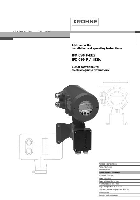
©KROHNE12 / 2002 7.30923.31.00<br />
Addition to the<br />
installation and operating instructions<br />
<strong>IFC</strong> <strong>090</strong> F-<strong>EEx</strong><br />
<strong>IFC</strong> <strong>090</strong> F / i-<strong>EEx</strong><br />
Signal converters for<br />
electromagnetic flowmeters<br />
Variable area flowmeters<br />
Vortex flowmeters<br />
Flow controllers<br />
Electromagnetic flowmeters<br />
Ultrasonic flowmeters<br />
Mass flowmeters<br />
Level measuring instruments<br />
Communications technology<br />
Engineering systems & solutions<br />
Switches, counters, displays and recorders<br />
Heat metering<br />
Pressure and temperature
WARNING !<br />
No changes regarding safety may be made to the devices. Unauthorized<br />
changes might affect the explosion safety of the devices.<br />
Be sure to follow these instructions !<br />
IMPORTANT ! • The prescriptions and regulations as well as the electrical data<br />
described in the EC-type examination certificate must be obeyed.<br />
• Beside the instructions for electrical installations in non-hazardous<br />
locations according to the applicable national standard (e.g. IEC 364),<br />
especially the regulations in EN 60079-14 "Electrical installations in<br />
hazardous locations" or equivalent national standard must be followed.<br />
• Installation, establishment, utilization and maintenance are only allowed<br />
to be executed by personnel with an education in explosion safety!<br />
These additional instructions are an extension to the Installation and Operating Instructions and<br />
only apply to the <strong>EEx</strong> version of the <strong>IFC</strong> <strong>090</strong> F - <strong>EEx</strong> or <strong>IFC</strong> <strong>090</strong> F / i -<strong>EEx</strong> signal converter. All<br />
technical information described in the “Installation and Operating Instructions” are applicable, when<br />
not specifically excluded, completed or replaced by the instructions in these additional instructions.<br />
Contents<br />
1 System components 3<br />
1.1 General information 3<br />
1.2 IFS x000 F-<strong>EEx</strong> primary head 3<br />
1.3 <strong>IFC</strong> <strong>090</strong> / … -<strong>EEx</strong> signal converter 4<br />
1.3.1 Electronic compartment 4<br />
1.3.2 Terminal compartment 4<br />
1.4 Data plates 5<br />
1.5 Electronic unit 5<br />
2 Electrical connection 7<br />
2.1 Equipotential bonding system 7<br />
2.2 Intermediate junction box ZD-<strong>EEx</strong> 7<br />
2.3 Connecting cables 7<br />
2.4 Connecting diagram 9<br />
2.5 regular <strong>IFC</strong> <strong>090</strong> - <strong>EEx</strong> electronic unit 11<br />
2.6 MODIS version <strong>IFC</strong> <strong>090</strong> I - <strong>EEx</strong> electronic unit 12<br />
2.7 Connecting diagrams MODIS 13<br />
3 Operation of the signal converter 20<br />
4 Maintenance 20<br />
5 Service 21<br />
5.1 General information for replacements 21<br />
5.2 Replacement of electronic unit 22<br />
5.3 Repalcement of power fuses 24<br />
5.4 Changing power supply voltage 27<br />
6 Ordering information 28<br />
7 Declaration of conformity 29<br />
8 EC-type examination certificates 30<br />
ALTOFLUX <strong>IFC</strong> <strong>090</strong> F-<strong>EEx</strong> and ALTOFLUX <strong>IFC</strong> <strong>090</strong> F / i-<strong>EEx</strong> 2
1 System components<br />
1.1 General information<br />
The ALTOFLUX <strong>IFC</strong> <strong>090</strong> F/…-<strong>EEx</strong> signal converter complies with the European Directive 94/9/EC<br />
(ATEX 100a) and has been approved for hazardous classified locations of Zone 1 and 2 by the<br />
KEMA conform the European Standards of the EN 500xx series. The <strong>IFC</strong> <strong>090</strong> F/…-<strong>EEx</strong> has the<br />
following EC-type examination Certificate number:<br />
KEMA 01 ATEX 2234<br />
The signal converter is available in two types, namely:<br />
<strong>IFC</strong> <strong>090</strong> F-<strong>EEx</strong> regular explosion protected version;<br />
<strong>IFC</strong> <strong>090</strong> F/i-<strong>EEx</strong>, MODIS version. This type has intrinsically safe signal output circuits, which are<br />
pro-vided by two installed MODIS modules (see Sect. 1.5 for details).<br />
The regular <strong>IFC</strong> <strong>090</strong> F-<strong>EEx</strong> signal converter is designed for ambient temperatures in the range of<br />
–40°C up to +60°C, the so-called MODIS version type <strong>IFC</strong> <strong>090</strong> F/i-<strong>EEx</strong> is rated for ambient<br />
temperatures from -20°C up to +60°C. Both types of signal converters are in remote design, which<br />
means that they are installed on a certain distance of the measuring unit, the IFS x000 F-<strong>EEx</strong><br />
series of primary heads. The primary heads are approved according to the European Directive<br />
94/9/EC (ATEX 100a) as well. Due to the installation on a distance from the primary head, the<br />
signal converter is independent of the process liquid temperature and therefore rated for<br />
temperature class T6 and a T85ºC for dusts.<br />
The <strong>IFC</strong> <strong>090</strong> F / … <strong>EEx</strong> signal converter is marked with the following code below:<br />
Regular version II 2GD <strong>EEx</strong> de [ib] IIC T6<br />
MODIS version II 2GD <strong>EEx</strong> de [ia] [ib] IIC T6<br />
Also see the EC-type Examination Certificate in Sect. 8 of these instructions.<br />
1.2 IFS x000 F-<strong>EEx</strong> primary head<br />
The IFS x000 F-<strong>EEx</strong> series primary head is the measuring unit of the <strong>IFC</strong> <strong>090</strong> F/…-<strong>EEx</strong> signal<br />
converter and contains two field coils and two electrodes in type of protection intrinsic safety<br />
category "ib" according to EN 50020. The type of protection of the field coils depends on the meter<br />
type and size, see the additional installation and operating instructions of the primary head<br />
concerned.<br />
The electrode circuits are wired by separate shielded cables and marked by the sheath color<br />
(white and purple). The intrinsical safe "ib" electrode circuits inside the IFS x000 F-<strong>EEx</strong> primary<br />
head have the following maximum values (entity parameters):<br />
Maximum input voltage U max = 20 V<br />
Maximum output current I max = 170 mA<br />
Maximum internal capacitance C i = 0<br />
Maximum internal inductance L i = 0<br />
The two field coils inside the primary head are connected in series and provided with the type of<br />
protection increased safety “e” conform to EN 50019 and additionally flameproof enclosure “d” in<br />
accordance with EN 50018 or encapsulation “m” according to EN 50028. The coils have a<br />
maximum resistance below 90 Ω per coil with a wire diameter of at least 0.25 mm and insulation<br />
class H (T max ≥ 180°C) according to IEC 85. The field coils are supplied with a square-wave signal<br />
with a peak voltage of 60 V maximum and a nominal current of 125 mA. The coil circuit is<br />
protected by two series fuses in the <strong>IFC</strong> <strong>090</strong> …-<strong>EEx</strong> electronics unit. The fuses are rated for a<br />
maximum voltage of 250 Vac @ 50-60 Hz, have a breaking capacity of at least 35 A and switching<br />
characteristics fast (F) to time-lag (T).<br />
ALTOFLUX <strong>IFC</strong> <strong>090</strong> F-<strong>EEx</strong> and ALTOFLUX <strong>IFC</strong> <strong>090</strong> F / i-<strong>EEx</strong> 3
1.3 <strong>IFC</strong> <strong>090</strong>/…-<strong>EEx</strong> signal converter<br />
The <strong>IFC</strong> <strong>090</strong>/…-<strong>EEx</strong> signal converter consists of the pre-certified cylindrical housing of die-casted<br />
aluminum (type AX/P-<strong>EEx</strong> with KEMA No. Ex-99.E.8128 U). It has two separate compartments,<br />
divided from each other by an integrated wall with casted flameproof terminal feed-through. The<br />
neck at the bottom of the housing that is connected to the wall-mounting bracket with junction box,<br />
contains flameproof cable feed-through type LC-2/<strong>EEx</strong>, which is approved by KEMA under No.<br />
Ex-01.E.2036 U. The wall-mounting bracket and junction box are also made of die-casted<br />
aluminium. The signal converter housing is on both ends closed by a cylindrical cover with<br />
M115x2-6H6g screw-thread and O-ring sealing. The signal converter has an ingress protection<br />
degree of IP 65 / IP 67 conform to EN 60529.<br />
1.3.1 Electronics compartment<br />
The electronics compartment accommodates the pre-certified <strong>IFC</strong> <strong>090</strong>…-<strong>EEx</strong> electronics unit with<br />
approval number PTB 98 ATEX 2012 U. The compartment is designed with type of protection<br />
flameproof enclosure "d" according to EN 50018 and closed by a threaded flameproof display<br />
cover. The <strong>IFC</strong> <strong>090</strong>…-<strong>EEx</strong> unit is inserted into the electronics compartment via two sliding rubbers<br />
that position and fixate it at the front in the housing. Two M4 screws mount the unit and a third M4<br />
screw fixates the copper earth strip at the back-end of the safety barrier printed circuit board. The<br />
three screws are screwed to the integrated aluminium wall in-between terminal and electronics<br />
compartment. The safety barrier provides the electrodes inside the primary head with type of<br />
protection intrinsic safety “ib” according to EN 50020.<br />
See tables on the next pages for the electrical data of the available power supplies (e.g. mains<br />
voltages, etc.). The safety barrier has the following maximum values (entity parameters):<br />
Maximum output voltage U 0 = 9 V<br />
Maximum output current I 0 = 38 mA<br />
Maximum allowed external capacitance C 0 = 4.9 µF<br />
Maximum allowed external inductance L 0 = 23 mH<br />
1.3.2 Terminal compartment<br />
The terminal compartment has seven M4 clamp terminals for connection of the power supply and<br />
signal output circuits (binary and current outputs). Section 2 shows the terminal arrangement for<br />
the regular and MODIS version of the <strong>IFC</strong> <strong>090</strong>/…-<strong>EEx</strong> signal converter. The terminals are<br />
separated from each other by insulation plates (nine in total, one at each end). The terminal<br />
arrangement of the MODIS version (i.e. <strong>IFC</strong> <strong>090</strong>i-<strong>EEx</strong>) is shown in Sect. 2.6. Two of the terminals<br />
are used for connection of the non-intrinsically safe power supply and four terminals (marked with<br />
"*") for the intrinsically safe, category "ia" signal outputs (i.e. current, pulse resp. status output) of<br />
the MODIS modules. The non-intrinsically and intrinsically safe terminals are separated from each<br />
other by a metal dividing plate, which is screwed to the remaining (not connected) M4 terminal.<br />
The two non-intrinsically safe power supply terminals are covered by an insulating plate.<br />
The terminal compartment (with standard type of protection increased safety "e") is standard<br />
equipped with two ATEX or E-generation approved "<strong>EEx</strong> e" cable glands. The terminal<br />
compartment can also be provided as a flameproof enclosure "d", in which case ATEX or E-<br />
generation approved "<strong>EEx</strong> d" cable glands of size Pg13.5, Pg16 or M20x1.5 are factory installed<br />
or must be installed by the customer. For flameproof conduit systems, the terminal compartment<br />
must have type of protection flameproof enclosure "d" according to EN 50018. The conduits must<br />
be sealed by "<strong>EEx</strong> d" approved (within the ATEX 100a directive) sealing devices (i.e. stopping<br />
box) directly at the conduit entrances of the as flameproof enclosure performed terminal<br />
compartment. All used cable glands, blind plugs and sealing devices for conduit systems must<br />
have an ingress protection degree of IP65 or better.<br />
ALTOFLUX <strong>IFC</strong> <strong>090</strong> F-<strong>EEx</strong> and ALTOFLUX <strong>IFC</strong> <strong>090</strong> F / i-<strong>EEx</strong> 4
1.4 Data plates<br />
<strong>IFC</strong> <strong>090</strong> F-<strong>EEx</strong><br />
<strong>IFC</strong> <strong>090</strong> F / i-<strong>EEx</strong><br />
1.5 Electronics unit<br />
The <strong>IFC</strong> <strong>090</strong> F/…-<strong>EEx</strong> signal converter can be equipped with the regular <strong>IFC</strong> <strong>090</strong>-<strong>EEx</strong> electronics<br />
unit or with the <strong>IFC</strong> <strong>090</strong>i-<strong>EEx</strong> electronics unit with intrinsically safe signal outputs (i.e. MODIS<br />
version). The regular signal converter design has type designation <strong>IFC</strong> <strong>090</strong> F-<strong>EEx</strong> and the MODIS<br />
version is designated as <strong>IFC</strong> <strong>090</strong> F/i-<strong>EEx</strong>.<br />
Regular <strong>IFC</strong> <strong>090</strong>-<strong>EEx</strong> electronics unit<br />
The <strong>IFC</strong> <strong>090</strong>-<strong>EEx</strong> can be equipped with one of the following power supplies, which depends on<br />
the mains supply voltage in area of application.<br />
Electrical data of power supply<br />
Power supply Terminal Description Supply voltage Tolerance Power<br />
AC-versions L Live<br />
115/230 Vac<br />
N Neutral<br />
-15%/+10% 10 VA<br />
100/200 Vac<br />
PE Protective Earth<br />
AC/DC-version 1L Live<br />
AC: -15%/+10% AC: 10 VA<br />
0L Neutral<br />
24V ac/dc<br />
DC: -25%/+30% DC: 8 W<br />
FE Functional Earth<br />
The above listed power supplies are protected by a mains fuse rated according the next table.<br />
ALTOFLUX <strong>IFC</strong> <strong>090</strong> F-<strong>EEx</strong> and ALTOFLUX <strong>IFC</strong> <strong>090</strong> F / i-<strong>EEx</strong> 5
Mains fuses<br />
Power supply<br />
Mains fuse<br />
Type Nominal voltage Rating Specifications<br />
AC-versions 100/115 Vac 200 mA Switching char.: fast (F) to time-lag (T)<br />
200/230 Vac 125 mA Breaking capacity: ≥ 1500 A @ 250 V<br />
24 Vac 1.25 A Switching char.: fast (F) to time-lag (T)<br />
DC-version 24 Vdc<br />
Breaking capacity: ≥ 300 A @ 65 V<br />
The <strong>IFC</strong> <strong>090</strong>-<strong>EEx</strong> electronics unit is equipped with the following in-/output circuits. Terminals B1,<br />
B⊥ and B2 can be configured as status or pulse outputs or as control inputs via the software. See<br />
the table below for the electrical data of these in-/output circuits.<br />
Electrical data of in-/output circuits<br />
Terminals Description Nominal voltage Maximum current<br />
B1, B⊥, B2 Pulse, status, control in-/outputs 32 V 150 mA<br />
I+, I Current output 15 V 22 mA<br />
The difference between 115/230 Vac version and the 100/200 Vac version is the number of the<br />
primary windings of the mains transformer.<br />
The terminals indicated as B1, B⊥ and B2 can be configured as pulse in-/outputs by jumpers.<br />
The <strong>IFC</strong> <strong>090</strong>-<strong>EEx</strong> electronics unit is provided with an extension module that is used for data<br />
communication (e.g. SMART, HART or RS485). In that case, the current output signal (I+, I) is<br />
superposed with a sinusoidal voltage signal of 0.5 V. The extension module does not significantly<br />
influence the nominal voltage U n , the nominal current I n or the power dissipation.<br />
Overheating protection<br />
The mains transformer is protected against overheating by a temperature breaker in series with<br />
the primary winding. The temperature breaker is casted within the compound of the transformer<br />
and has an opening temperature of 125 °C (± 5 K).<br />
<strong>IFC</strong> <strong>090</strong>i-<strong>EEx</strong> unit with MODIS modules<br />
The <strong>IFC</strong> <strong>090</strong>i-<strong>EEx</strong> electronics unit is equipped with two MODIS-modules. It is equipped with one of<br />
the following power supplies.<br />
Electrical data of <strong>IFC</strong> <strong>090</strong>i-<strong>EEx</strong> electronics unit<br />
Power supply Terminal Function Electrical data<br />
AC-version L<br />
N<br />
PE<br />
Live<br />
Neutral<br />
Protective ground<br />
AC/DC-version<br />
1L <br />
0L <br />
FE<br />
Live<br />
Neutral<br />
Functional ground<br />
U n = 100…230 Vac –15%/+10%<br />
P n = approx. 15 VA<br />
Primary fuse: Rated current: 1.6 A<br />
Design conform IEC 127-2<br />
Breaking capacity: 1500 A<br />
U n = 24 V ac / dc<br />
AC: -15%/+10% or 20.4…26.4 V ac<br />
DC: -25% / +30% or 18…32 V dc<br />
I n = approx. 490…630 mA for AC<br />
approx. 310…550 mA for DC<br />
P n = approx. 10 W<br />
Primary fuse: Rated current: 1.25 A<br />
Design conform IEC 127-2<br />
Breaking capacity: 1500 A<br />
NOTE:<br />
The mains fuses for both electronics units are listed in Sect. 6 of this manual.<br />
ALTOFLUX <strong>IFC</strong> <strong>090</strong> F-<strong>EEx</strong> and ALTOFLUX <strong>IFC</strong> <strong>090</strong> F / i-<strong>EEx</strong> 6
2 Electrical connection<br />
2.1 Equipotential bonding system<br />
The <strong>IFC</strong> <strong>090</strong> F/…-<strong>EEx</strong> signal converter must always be incorporated into the equipotential<br />
bonding system of the hazardous area. This connection can be achieved through the PE/FE<br />
conductor connected to the PE terminal in the terminal compartment (see figure of terminal<br />
arrangement) or through a separate PE conductor, cross sectional area at least 4 mm 2 , connected<br />
to the external PE clamp, placed below the converter housing.<br />
2.2 Intermediate junction box ZD-<strong>EEx</strong><br />
For safety reasons, standard cables with a rubber or thermoplastic insulation sheath may only be<br />
used up to a continuous operating temperature of 70°C at the cable entry and 80°C at the<br />
branching point of the connecting cables. In case that the temperature at the above mentioned<br />
parts exceed the maximum values, heat-resistant cables must be installed at the IFS x000 F-<strong>EEx</strong><br />
primary head in remote design. Also see the EC-type examination certificate of the primary head.<br />
The table below summarizes the conditions for use of heat-resistant cables for the IFS x000 F-<br />
<strong>EEx</strong> primary head.<br />
Use of heat-resistant cables<br />
Primary head Meter size Ambient temperature Process liquid temperature<br />
IFS 4000 F-<strong>EEx</strong> DN25 - 150 ≤ 40°C<br />
≤ 50°C<br />
≤ 60°C<br />
not required<br />
≥ 155°C<br />
≥ 105°C<br />
≥ DN200 ≤ 40°C<br />
≤ 50°C<br />
≤ 60°C<br />
IFS 5000 F-<strong>EEx</strong> DN2.5 - 100 ≤ 40°C<br />
≤ 50°C<br />
≤ 60°C<br />
IFS 6000 F-<strong>EEx</strong> DN2.5 - 80 ≤ 40°C<br />
≤ 50°C<br />
≤ 60°C<br />
not required<br />
≥ 145°C<br />
≥ 110°C<br />
≥ 165°C<br />
≥ 130°C<br />
≥ 100°C<br />
not required<br />
≥ 160°C<br />
≥ 115°C<br />
In case that heat-resistant cables are required, install the intermediate junction box ZD-<strong>EEx</strong> at a<br />
distance of approximately 5 m from the primary head. Connect heat-resistant cables (see cables<br />
D and E in the next section) between the primary head’s junction box and the intermediate<br />
junction box ZD-<strong>EEx</strong>. The standard cables (types B and C) can be used between the <strong>IFC</strong> <strong>090</strong><br />
F/…-<strong>EEx</strong> signal converter and intermediate junction box. See connection diagram 2.<br />
The silicone rubber insulated connection cable for the magnetic field coils must be protected<br />
against mechanical damages between the primary head and intermediate junction box by a<br />
conduit system with edge protections. Intermediate box ZD-<strong>EEx</strong> has terminals with type of<br />
protection increased safety “e” conform to EN 50019. The intermediate box is incorporated in the<br />
equipotential bonding system of the installation via its external clamp terminal.<br />
2.3 Connecting cables<br />
NOTE: The following described cables are shown in the next connection diagrams.<br />
Cable A<br />
Signal cable for current output and binary outputs (pulse and status output): The cable parameters<br />
must be in accordance with the regulations in the EN 60079-14 "Electrical installations in<br />
hazardous locations" or an equivalent national standard. For the MODIS version with <strong>IFC</strong> <strong>090</strong>i-<br />
<strong>EEx</strong> electronics unit (right detail in connection diagram 1) the signal cable for the intrinsically safe<br />
signal in-/outputs must also conform the requirements as specified in the relevant standard<br />
national code of practice for the installation of electrical apparatus with type of protection Intrinsic<br />
Safety "i".<br />
ALTOFLUX <strong>IFC</strong> <strong>090</strong> F-<strong>EEx</strong> and ALTOFLUX <strong>IFC</strong> <strong>090</strong> F / i-<strong>EEx</strong> 7
Cable B<br />
Power supply cable: The cable parameters must be in accordance with the regulations of the EN<br />
60079-14 "Electrical installations in hazardous locations" or an equivalent national standard.<br />
The PE terminal must be connected to the protective ground conductor of the mains supply.<br />
Rated voltage<br />
≥ 500 V<br />
Cross-sectional area of core 1.5 to 2.5 mm 2<br />
Examples<br />
H07...-., H05...-.<br />
Cable C<br />
3 3<br />
6<br />
4<br />
7<br />
1<br />
1<br />
2<br />
3<br />
4<br />
5<br />
6<br />
7<br />
8<br />
Type DS blue<br />
Intrinsical safe, with double shielding<br />
1 Stranded drain wire,<br />
1st shield, 1.5 mm 2<br />
2 Insulation<br />
3 Stranded wire, 0.5 mm 2<br />
4 Special foil, 1st shield<br />
5 Insulation<br />
6 Mu-metal foil, 2nd shield<br />
7 Stranded drain wire,<br />
2nd shield, 0.5 mm 2<br />
8 Outer sheath<br />
(flame-retardant)<br />
Cable constants (typical<br />
values at Ta = 20°C)<br />
C’3/3 60 pF/m (1 kHz)<br />
C’3/4 110 pF/m (1 kHz)<br />
C’4/6 290 pF/m (1 kHz)<br />
L’3/3 0.85 µH/m (1 kHz)<br />
L’3/4 0.60 µH/m (1 kHz)<br />
R’3 37 mΩ/m<br />
R’4+1 12 mΩ/m<br />
Cable D<br />
Intrinsical safe, with single shielding. Heat-resistant conform to VDE 0165/02.91.<br />
Properties<br />
Continuous service temperature ≥ 120°C<br />
Test voltage<br />
≥ 500 V<br />
Capacitance:<br />
≤ 200 pF/m<br />
≤ 200 pF/m<br />
Inductance:<br />
≤ 1µH/m<br />
Cable length<br />
≤ 5 m<br />
Single-wire-Ø:<br />
≥ 0.1 mm<br />
Cross-sectional area of core 0.5 to 1.5 mm 2<br />
Sheath<br />
light-blue or in other way color-coded as intrinsical safe,<br />
flame-retardant.<br />
Example<br />
Silicone rubber insulated, shielded control cable.<br />
Cable E<br />
Non-intrinsical safe, 2-core without shielding. Heat-resistant conform to VDE 0165/02.91.<br />
Properties<br />
Continuous service temperature ≥ 120°C<br />
Test voltage<br />
≥ 500 V<br />
Cross-sectional area of core 1.5 mm 2<br />
Bonding conductor<br />
Cross-sectional area Max. 4 mm 2<br />
ALTOFLUX <strong>IFC</strong> <strong>090</strong> F-<strong>EEx</strong> and ALTOFLUX <strong>IFC</strong> <strong>090</strong> F / i-<strong>EEx</strong> 8
2.4 Connection diagrams<br />
Connection diagram 1: Standard cables<br />
SIGNAL IN-/OUTPUTS L N PE 100-230 Vac<br />
L L FE 24 Vac/dc<br />
INTRINSICALLY SAFE<br />
SIGNAL IN-/OUTPUTS L N PE 100-230 Vac<br />
(i.e. MODIS) L L FE 24 Vac/dc<br />
A<br />
B<br />
A<br />
B<br />
<strong>IFC</strong> <strong>090</strong>-<strong>EEx</strong><br />
Signal Converter<br />
B1 B⊥ B2 I+ I L N<br />
BINARY CURRENT MAINS<br />
OUTPUTS OUTPUT SUPPLY<br />
TERMINAL COMPARTMENT<br />
Standard "<strong>EEx</strong> e" (Optional "<strong>EEx</strong> d")<br />
ELECTRONICS COMPARTMENT (always "<strong>EEx</strong> d")<br />
electrode circuits<br />
field coil circuits<br />
PE<br />
FE<br />
<strong>IFC</strong> <strong>090</strong>i-<strong>EEx</strong><br />
Signal Converter<br />
OPTION: MODIS<br />
Flameproof (<strong>EEx</strong> d)<br />
terminal feed-through<br />
x x x x 1L 0L<br />
PE<br />
FE<br />
Unused terminal<br />
Separation plate<br />
Flameproof (<strong>EEx</strong> d) cable<br />
feed-through<br />
EQUIPOTENTIAL BONDING CONDUCTOR ≥ 4 mm 2 (OPTIONAL)<br />
Electrode cables<br />
E<br />
Coil<br />
Flow tube<br />
Coil<br />
E<br />
Field coil wires<br />
Hazardous locations<br />
of Zone 1 and 2<br />
IFS x000…-<strong>EEx</strong><br />
Primary Head<br />
Intrinsically safe electrode circuits<br />
Increased safe field coil circuit<br />
ALTOFLUX <strong>IFC</strong> <strong>090</strong> F-<strong>EEx</strong> and ALTOFLUX <strong>IFC</strong> <strong>090</strong> F / i-<strong>EEx</strong> 9
Connection diagram 2: Use of heat-resistant cables<br />
Signal Converter<br />
<strong>IFC</strong> <strong>090</strong> F/…-<strong>EEx</strong><br />
ELECTRONICS COMPARTMENT (always "<strong>EEx</strong> d")<br />
Intrinsical safe ("ib") Increased safe ("e")<br />
electrode circuits field coil circuits<br />
(No. "3", "2", "1") (No. "7", "8")<br />
2x fuse<br />
160mA<br />
Flameproof (<strong>EEx</strong> d) cable<br />
feed-through LC-2/<strong>EEx</strong><br />
3 2 1 7 8<br />
C<br />
B<br />
Hazardous locations<br />
of Zone 1 and 2<br />
EQUIPOTENTIAL BONDING CONDUCTOR ≥ 4 mm 2 (OPTIONAL)<br />
Electrode cables - white/pink<br />
(PTFE insulated shielded copper)<br />
D<br />
3 2 1 7 8<br />
3 2 1 7 8<br />
Coil<br />
Flow tube<br />
E<br />
E<br />
Coil<br />
IFS x000 F-<strong>EEx</strong><br />
E<br />
ZD-<strong>EEx</strong><br />
intermediate<br />
junction box<br />
E = electrode<br />
Field coil wires - green/blue<br />
(PTFE insulated copper)<br />
Primary Head type<br />
ALTOFLUX <strong>IFC</strong> <strong>090</strong> F-<strong>EEx</strong> and ALTOFLUX <strong>IFC</strong> <strong>090</strong> F / i-<strong>EEx</strong> 10
2.5 Regular <strong>IFC</strong> <strong>090</strong>-<strong>EEx</strong> electronics unit<br />
The field cables that enter the terminal compartment of the <strong>IFC</strong> <strong>090</strong>-<strong>EEx</strong> signal converter unit (i.e.<br />
power supply, current and binary outputs) are non-intrinsically safe. To connect external devices<br />
to the signal output terminals, the wiring requirements for the type of protection of the<br />
compartment (standard: increased safety "e", optional: flameproof "d") must be conform to the<br />
international or national standard involved (e.g. EN 60079-14).<br />
Terminal arrangement in terminal compartment<br />
pulse and status outputs<br />
or control inputs<br />
binary<br />
outputs<br />
current<br />
output<br />
100 - 240 V AC / 48 - 63 Hz<br />
24 V AC / DC<br />
PE<br />
FE<br />
Protective earth<br />
Functional earth<br />
Passive pulse/status output<br />
Active current output<br />
I ≤ 150 mA<br />
electronic<br />
or electromechanical<br />
totalizer<br />
I ≤ 150 mA<br />
U ext ≤ 32 V DC<br />
≤ 24 V AC<br />
e.g.<br />
signal<br />
indicator<br />
R i ≤ 500 Ω<br />
Note:<br />
The binary outputs (terminals B1, B⊥ and B2) can only be configured as passive<br />
outputs, the current output (terminals I+ and I) can only be configured as active output.<br />
For power supply versions with the nominal voltage in the range of 100 to 230 Vac the PE<br />
conductor must always be connected to the M5 clamp terminal marked with the safety earth<br />
symbol that is press-fitted in the dividing aluminium wall of the signal converter housing. For the<br />
24 Vac/dc power supply, the PE conductor may be connected, but it not required for the safety of<br />
tthe flowmeter. The terminal arrangement is shown above.<br />
ALTOFLUX <strong>IFC</strong> <strong>090</strong> F-<strong>EEx</strong> and ALTOFLUX <strong>IFC</strong> <strong>090</strong> F / i-<strong>EEx</strong> 11
2.6 MODIS version <strong>IFC</strong> <strong>090</strong>i-<strong>EEx</strong> electronics unit<br />
The field cables of the non-intrinsically safe power supply and the intrinsically safe, category "ia"<br />
signal outputs enter the terminal compartment of the <strong>IFC</strong> <strong>090</strong>i-<strong>EEx</strong> signal converter unit via two<br />
separate entrances. To connect external devices to the intrinsically safe signal output terminals,<br />
the wiring requirements for their type of protection as well as of the compartment (standard:<br />
increased safety "e", optional: flameproof enclosure "d") must be conform to the international or<br />
national standard involved (e.g. EN 60079-14).<br />
Terminal arrangement in terminal compartment<br />
NC = not connected<br />
Metal dividing<br />
plate IS / non-IS<br />
terminals<br />
Connecting terminals<br />
for intrinsically safe<br />
signal in-/outputs<br />
Connecting<br />
terminals for<br />
non-intrinsically<br />
safe power supply<br />
* * * *<br />
NC 1L 0L 24 Vac/dc<br />
L N 100…240<br />
PE<br />
Protective Earth terminal<br />
Cable entrance for<br />
intrinsically safe<br />
signal cable<br />
Cable entrance for<br />
non-intrinsically<br />
safe power supply<br />
cable<br />
The non-intrinsically safe terminals for connection of the power supply (1L and 0L) must be<br />
connected according to the relevant standard code of practice for electrical apparatus intended for<br />
use in potentially hazardous locations, type of protection Increased Safety "e" or type of protection<br />
Flameproof Enclosure "d", depending on the type of protection of the terminal compartment of the<br />
signal converter housing.<br />
To gain access to the connection terminals of the power supply, the half-circular cover plate of<br />
insulating material must be slightly lifted at one end and then rotated downwards, see the<br />
instruction on the cover plate. After connection of the power supply cable, the half-circular cover<br />
plate must be restored into its original position, so that the minimum clearances and creepage<br />
distances towards the intrinsically safe signal in-/output terminals are maintained.<br />
For details, see diagram on terminal compartment MODIS on next page.<br />
ALTOFLUX <strong>IFC</strong> <strong>090</strong> F-<strong>EEx</strong> and ALTOFLUX <strong>IFC</strong> <strong>090</strong> F / i-<strong>EEx</strong> 12
Terminal compartment MODIS version <strong>IFC</strong> <strong>090</strong>i-<strong>EEx</strong><br />
Insulating cover plate<br />
Sticker with handling information<br />
for insulating cover plate<br />
Sticker indicating the intrinsically<br />
safe signal in-/output circuits<br />
The PE (or FE) conductor must be connected to the press-fitted M5 clamp terminal marked inside<br />
the terminal compartment. This conductor must be guided through the rectangular opening in the<br />
metal dividing plate that separates the non-intrinsically safe power supply terminals from the<br />
intrinsically safe signal in-/output terminals.<br />
2.7 Connection diagrams MODIS<br />
Sect. 2.4 shows the block diagrams of the <strong>EEx</strong> electromagnetic compact flowmeter. The power<br />
supply (terminals 1L, 0L) is connected via cable B. The PE terminal must be connected to the<br />
protective earth conductor of the mains supply.<br />
The <strong>IFC</strong> <strong>090</strong>i-<strong>EEx</strong> electronics unit is provided with intrinsically safe signal in-/output circuits due to<br />
the installed pair of MODIS modules in accordance with the table below.<br />
ALTOFLUX <strong>IFC</strong> <strong>090</strong> F-<strong>EEx</strong> and ALTOFLUX <strong>IFC</strong> <strong>090</strong> F / i-<strong>EEx</strong> 13
Overview of MODIS modules<br />
Module Terminal designation Function / Intrinsically safe maximum data<br />
P-SA I ⊥, I Current output (0/4-20 mA), passive<br />
U i = 30 V, I i = 250 mA, P i = 1.0 W<br />
C i = 5 nF, L i ≈ 0<br />
FA-ST B1, B1⊥ or B2, B2 ⊥ Pulse (frequency) output or status in-/output, all passive<br />
The function can be set by software<br />
U i = 30 V, I i = 250 mA, P i = 1.0 W<br />
C i = 5 nF, L i ≈ 0<br />
F-PA D, D ⊥ Fieldbus module, type Profibus system, passive<br />
U i = 30 V, I i = 300 mA, P i = 4.2 W<br />
C i = 5 nF, L i ≈ 0<br />
F-FF D, D ⊥ Fieldbus module, type Fieldbus Foundation, passive<br />
U i = 30 V, I i = 300 mA, P i = 4.2 W<br />
C i = 5 nF, L i ≈ 0<br />
DC-I I+, B1+ Intrinsically safe voltage source for the passive module<br />
P-SA or FA-ST, so that active operation is possible.<br />
U o = 23.5 V, I o = 98 mA, P o = 0.6 W<br />
C o = 132 nF, L o = 4 mH<br />
Note!<br />
When modules P-SA (or FA-ST) and DC-I are connected<br />
in series, the internal capacitance C i of 5 nF must be<br />
subtracted from the C o of 132 nF. So the data plate will<br />
list a C o of 127 nF.<br />
Besides the shown intrinsically safe maximum values for voltages and current -which are based<br />
on certain fault conditions as prescribed by the standard EN 50 020 - the nominal values for<br />
current and voltage must also be respected otherwise a proper functioning of the modules is not<br />
guaranteed!<br />
Nominal voltage and current values for the MODIS modules<br />
MODIS module<br />
P-SA<br />
(passive current output )<br />
FA-ST<br />
(frequency / pulse / status output<br />
or control input)<br />
Nominal values for voltage and current<br />
Current:<br />
4 ... 20 mA<br />
Working voltage:<br />
8 ... 30V<br />
Voltage drop :<br />
8V at 4mA<br />
Working voltage:<br />
6 ... 30V<br />
Working current:<br />
110 mA<br />
Voltage drop: in ON-state: < 2V at 110 mA<br />
Leakage current in OFF-state: < 900 µA at 30V<br />
DC-I<br />
(active voltage source)<br />
Control input:<br />
Input voltage LOW level:<br />
Input voltage HIGH level:<br />
Frequency range :<br />
Voltage:<br />
Current:<br />
Internal resistance:<br />
< 3V<br />
> 7V<br />
0 .. 12 KHz<br />
20V<br />
30 mA<br />
260 Ω<br />
ALTOFLUX <strong>IFC</strong> <strong>090</strong> F-<strong>EEx</strong> and ALTOFLUX <strong>IFC</strong> <strong>090</strong> F / i-<strong>EEx</strong> 14
The active module DC-I is needed in the 24 Vac/dc power supply version to form an active current<br />
or pulse output in combination with one of the passive modules P-SA or FA-ST. Due to limited<br />
space it is not available for 100...230 Vac supply versions.<br />
Possible combinations of the installed MODIS modules for the 24 Vac/dc power supply<br />
version of the <strong>IFC</strong> <strong>090</strong>i-<strong>EEx</strong><br />
<strong>IFC</strong> <strong>090</strong>i-<strong>EEx</strong> version Part No. MODIS modules Terminal designation<br />
Ex-i1 2.11582.01.00 P-SA FA-ST I ⊥ I B1 B1⊥<br />
Ex-i2 2.11582.03.00 P-SA F-PA I ⊥ I D D ⊥<br />
Ex-i3 2.11582.02.00 P-SA DC-I I+ I<br />
Ex-i4 2.11582.05.00 FA-ST F-PA B1 B1⊥ D D ⊥<br />
Ex-i5 2.11582.06.00 FA-ST DC-I B1+ B1<br />
Ex-i6 2.11582.07.00 FA-ST FA-ST B2 B2⊥ B1 B1 ⊥<br />
Ex-i7 2.11582.08.00 P-SA F-FF I ⊥ I D D ⊥<br />
Ex-i8 2.11582.09.00 FA-ST F-FF B1 B1⊥ D D ⊥<br />
Possible combinations of the installed MODIS modules for the 100-230 Vac power supply<br />
version of the <strong>IFC</strong> <strong>090</strong>i-<strong>EEx</strong><br />
<strong>IFC</strong> <strong>090</strong>i-<strong>EEx</strong> version Part No. MODIS modules Terminal designation<br />
Ex-i1 2.12253.01.00 P-SA FA-ST I ⊥ I B1 B1⊥<br />
Ex-i2 2.12253.02.00 P-SA F-PA I ⊥ I D D ⊥<br />
Ex-i4 2.12253.03.00 FA-ST F-PA B1 B1⊥ D D ⊥<br />
Ex-i6 2.12253.04.00 FA-ST FA-ST B2 B2⊥ B1 B1 ⊥<br />
Ex-i7 2.12253.05.00 P-SA F-FF I ⊥ I D D ⊥<br />
Ex-i8 2.12253.06.00 FA-ST F-FF B1 B1⊥ D D ⊥<br />
Due to mechanical and electrical limitations, only the listed pairs of MODIS modules are possible.<br />
The two modules each use two terminals of the bottom four terminals of the flameproof terminal<br />
feed-through in the dividing wall between the electronics and terminal compartment of the signal<br />
converter housing, except for the combination with module DC-I (only applicable for 24 Vac/dc<br />
versions), where only two of the four terminals are used. Interconnection of the two modules, P-<br />
SA with DC-I or FA-ST with DC-I is made internally.<br />
The flameproof terminal feed-through has seven terminals in total, the top two terminals are used<br />
for connection of the power supply, the third one is only used for mounting of a metal dividing<br />
plate with insulating cover plate. The remaining four are used for the intrinsically safe signal in-<br />
/output circuits of the installed MODIS modules.<br />
The metal dividing plate and the insulating cover plate warrant the required separation distances<br />
(i.e. clearances, creepage distances and distances through insulation) between the nonintrinsically<br />
safe power supply terminals and the intrinsically safe signal in-/output circuits. The<br />
insulating cover plate is provided with a sticker that contains important instructions how to remove<br />
and re-install the cover plate and the conditions under which it should be established (circuits not<br />
live !).<br />
Important !<br />
Carefully follow the instructions on the sticker that is glued to the top of the<br />
insulating cover plate that covers the non-intrinsically safe power supply<br />
terminals !<br />
ALTOFLUX <strong>IFC</strong> <strong>090</strong> F-<strong>EEx</strong> and ALTOFLUX <strong>IFC</strong> <strong>090</strong> F / i-<strong>EEx</strong> 15
For the connection diagrams of the intrinsically safe signal in-/outputs of the installed MODIS<br />
modules in the <strong>IFC</strong> <strong>090</strong>i-<strong>EEx</strong> electronics unit (see next pages). It has to be noted that the<br />
intrinsically safe signal in-/outputs may only be connected to the following listed apparatus<br />
(registering devices like amp-meters, pulse counters, etc.):<br />
<strong>EEx</strong>-approved intrinsically safe apparatus;<br />
<strong>EEx</strong>-approved associated apparatus;<br />
Passive apparatus as defined in your national standard for installation of electrical apparatus in<br />
hazardous locations (e.g. EN 60079-14).<br />
Other types of apparatus may only be connected to the intrinsically safe signal in-/outputs through<br />
<strong>EEx</strong>-approved safety barriers, isolating interface units and the like. These barriers or units are not<br />
depicted in the connection diagrams for reasons of readability. It is assumed that they are an<br />
integrated part of the registering devices or as separate devices connected in series with them.<br />
The registering devices may only be installed in the hazardous location if they also have a type of<br />
protection for explosion safety according to the European Standards of the EN 500xx series, or if<br />
they are constructed as prescribed in your standard national code of practice.<br />
When the intrinsically safe signal in-/outputs are connected to other intrinsically safe or associated<br />
apparatus, the maximum safety values (i.e. entity parameters) of all intrinsically safe circuits have<br />
to be considered.<br />
Important !<br />
The 100…230 Vac power supply versions of the <strong>IFC</strong> <strong>090</strong>i-<strong>EEx</strong> signal converter<br />
electronics unit with MODIS modules can only be equipped with passive outputs.<br />
Therefore the connection diagrams with the numbers 2, 4, 5, 7, 9, 11 and 12 are<br />
applicable for the 100…230 Vac power supply versions.<br />
ALTOFLUX <strong>IFC</strong> <strong>090</strong> F-<strong>EEx</strong> and ALTOFLUX <strong>IFC</strong> <strong>090</strong> F / i-<strong>EEx</strong> 16
Connection diagrams 1 to 4 of the intrinsically safe signal in-/outputs<br />
1 Current output I active 2 Current output I passive<br />
Version: Ex-i3 Versions: Ex-i1, Ex-i2, Ex-i7<br />
I = 4 - 20 mA<br />
U ext = 8.1 - 30 V<br />
R i = 350 Ω<br />
I = 4 - 20 mA<br />
R i ≤ (U ext - 8) / 0.022<br />
<strong>IFC</strong> <strong>090</strong> i-<strong>EEx</strong><br />
<strong>IFC</strong> <strong>090</strong> i-<strong>EEx</strong><br />
hazardous area<br />
hazardous area<br />
safe area or<br />
safe area or<br />
hazardous area ( * ) hazardous area ( * )<br />
3 Pulse output P active 4 Pulse output P passive<br />
Version: Ex-i5 Versions: Ex-i1, Ex-i4, Ex-i6, Ex-i8<br />
U int = 20 V DC<br />
U ext = 6 - 30 V DC<br />
R int = 260 Ω<br />
I max ≤ 110 mA<br />
U L = 20×R L / (260+R L )<br />
<strong>IFC</strong> <strong>090</strong> i-<strong>EEx</strong><br />
<strong>IFC</strong> <strong>090</strong> i-<strong>EEx</strong><br />
hazardous area<br />
hazardous area<br />
safe area or<br />
safe area or<br />
hazardous area ( * ) hazardous area ( * )<br />
passive counter<br />
passive counter with<br />
external supply<br />
( * ) Important note: Only if the measuring devices are also explosion protected<br />
ALTOFLUX <strong>IFC</strong> <strong>090</strong> F-<strong>EEx</strong> and ALTOFLUX <strong>IFC</strong> <strong>090</strong> F / i-<strong>EEx</strong> 17
Connection diagrams 5 to 8 of the intrinsically safe signal in-/outputs<br />
5 Pulse output P passive 6 Status output S active<br />
Versions: Ex-i1, Ex-i4, Ex-i6, Ex-i8 Version: Ex-i5<br />
U ext = 6 - 30 V<br />
U int = 20 V DC<br />
I max ≤ 110 mA<br />
R int = 260 Ω<br />
for active EC U L = 20×R L / (260+R L )<br />
<strong>IFC</strong> <strong>090</strong> i-<strong>EEx</strong><br />
<strong>IFC</strong> <strong>090</strong> i-<strong>EEx</strong><br />
hazardous area<br />
hazardous area<br />
safe area or<br />
safe area or<br />
hazardous area ( * ) hazardous area ( * )<br />
active counter<br />
7 Status output S passive 8 Control input C active<br />
Versions: Ex-i1, Ex-i4, Ex-i6, Ex-i8 Version: Ex-i5<br />
U ext = 6 - 30 V<br />
U int = 20 V DC<br />
I max ≤ 110 mA<br />
I contact ≤ 6 mA<br />
Connection to terminals B1/B1⊥ and/or<br />
B2/B2⊥<br />
<strong>IFC</strong> <strong>090</strong> i-<strong>EEx</strong><br />
<strong>IFC</strong> <strong>090</strong> i-<strong>EEx</strong><br />
hazardous area<br />
hazardous area<br />
safe area or<br />
safe area or<br />
hazardous area ( * ) hazardous area ( * )<br />
( * ) Important note: Only if the measuring devices are also explosion protected !<br />
ALTOFLUX <strong>IFC</strong> <strong>090</strong> F-<strong>EEx</strong> and ALTOFLUX <strong>IFC</strong> <strong>090</strong> F / i-<strong>EEx</strong> 18
Connection diagrams 9 to 12 of the intrinsically safe signal in-/outputs<br />
9 Control input C passive 10 HART active<br />
Versions: Ex-i1, Ex-i4, Ex-i6, Ex-i8 Version: Ex-i3<br />
U ext = 7 - 30 V DC<br />
Connection to terminals B1/B1⊥ and/or<br />
B2/B2⊥<br />
<strong>IFC</strong> <strong>090</strong> i-<strong>EEx</strong><br />
<strong>IFC</strong> <strong>090</strong> i-<strong>EEx</strong><br />
hazardous area<br />
hazardous area<br />
safe area or<br />
safe area or<br />
hazardous area ( * ) hazardous area ( * )<br />
to HART<br />
communicator<br />
or SMART converter<br />
11 HART passive 12 Fieldbus<br />
Versions: Ex-i1, Ex-i2, Ex-i7 Versions: Ex-i2, Ex-i4, Ex-i7, Ex-i8<br />
<strong>IFC</strong> <strong>090</strong> i-<strong>EEx</strong><br />
<strong>IFC</strong> <strong>090</strong> i-<strong>EEx</strong><br />
to next HART device<br />
hazardous area<br />
safe area or<br />
hazardous area ( * )<br />
Bus supply device<br />
to HART<br />
communicator<br />
or SMART converter<br />
Bus supply device<br />
to next Fieldbus<br />
device<br />
or bus terminator<br />
hazardous area<br />
safe area or<br />
hazardous area ( * )<br />
to Bus master<br />
Bus supply device<br />
( * ) Important note: Only if the measuring devices are also explosion protected !<br />
ALTOFLUX <strong>IFC</strong> <strong>090</strong> F-<strong>EEx</strong> and ALTOFLUX <strong>IFC</strong> <strong>090</strong> F / i-<strong>EEx</strong> 19
3 Operation of the signal converter<br />
The <strong>IFC</strong> <strong>090</strong> F/…-<strong>EEx</strong> signal converter unit is equipped with a display unit that contains magnetic<br />
Hall sensors. These HalI sensors enable the settings of the <strong>IFC</strong> <strong>090</strong>…-<strong>EEx</strong> electronics unit to be<br />
set resp. reset with aid of the with the apparatus delivered bar magnet without the necessity to<br />
open the flameproof converter housing in the hazardous area.<br />
For the program functions and settings of the converter the standard Installation and operating<br />
instructions have to be consulted. It must be noted that - depending on the <strong>IFC</strong><strong>090</strong> i-<strong>EEx</strong> version<br />
installed - not all output/input functions are available.<br />
Following menus do not apply for the <strong>IFC</strong><strong>090</strong> i-<strong>EEx</strong> versions Ex-i2 and Ex-i3:<br />
(see also Sect. 4.4. "Table of settable functions" in the standard "Installation and operating<br />
instructions" of the <strong>IFC</strong><strong>090</strong> K/F signal converter)<br />
1.01 VALUE P<br />
1.06 Output/input B1<br />
1.07 Output/input B2<br />
1.06 PULS B1<br />
1.06 STATUS B1<br />
1.07 STATUS B2<br />
1.06 CONTROL B1<br />
1.07 CONTROL B2<br />
3.02 VALUE P<br />
3.07 HARDWARE<br />
Fct. Text Description and settings<br />
1.00 1.00 OPERATION Operations menu<br />
1.01 FULL SCALE ...<br />
VALUE P<br />
1.06 Output/Input B1<br />
1.07 Output/Input B2<br />
1.06 PULS B1<br />
1.06<br />
1.07<br />
STATUS B1<br />
STATUS B2<br />
1.06<br />
1.07<br />
CONTROL B1<br />
CONTROL B2<br />
3.00 3.00 INSTALL. Installation menu<br />
3.02 FLOWMETER ...<br />
VALUE P<br />
3.07 HARDWARE<br />
As a consequence, the chapters included in the standard Installations and operating instructions,<br />
giving detailed descriptions of these menus, must be skipped.<br />
4 Maintenance<br />
The <strong>IFC</strong> <strong>090</strong> F/…-<strong>EEx</strong> signal converter is maintenance free with regard to the flowmetering<br />
properties. Within the scope of the periodical inspections, which are required for electrical<br />
apparatus that are installed and used in hazardous classified locations, it is recommended to<br />
check the flameproof enclosure on signs of damage or corrosion. This concerns the converter<br />
housing.<br />
ALTOFLUX <strong>IFC</strong> <strong>090</strong> F-<strong>EEx</strong> and ALTOFLUX <strong>IFC</strong> <strong>090</strong> F / i-<strong>EEx</strong> 20
5 Service<br />
See Sect. 6 or contact your (local) KROHNE sales representative for the ordering information of<br />
spare parts or replacements of <strong>IFC</strong> <strong>090</strong>…-<strong>EEx</strong> electronics units and/or power fuses.<br />
5.1 General information for replacements<br />
IMPORTANT !<br />
The following instructions must be followed carefully, if the <strong>IFC</strong> <strong>090</strong>/…-<strong>EEx</strong><br />
signal converter housing has to be opened respectively closed again!<br />
Before opening<br />
Make absolutely sure there is no explosion hazard!<br />
If necessary provide a ”Gas-free certificate” !<br />
Make sure that all connecting cables are safely isolated from the power supply !<br />
When the instructions above are strictly followed, the cover (with glass window) of the electronics<br />
compartment may be removed. First unscrew the recessed head screw of the interlocking device<br />
by a hollow-head screw wrench size 3, until the cover can rotate freely. Unscrew the cover with<br />
the special plastic wrench (black) that is supplied with the apparatus.<br />
After opening<br />
The copper ground strip at the back of the electronics unit must be securely screwed to the<br />
housing (back-end of electronics compartment) by screw SE (see figure below). The electronics<br />
unit is screwed into the electronics compartment by two screws D. Before screws SE and D can<br />
be accessed, the display unit must be removed via screws A.<br />
Before the cover is screwed back into the housing, the screw-thread must be clean and wellgreased<br />
with an acid and resin-free grease, e.g. silicone grease.<br />
Screw the cover as tight as possible into the housing by hand, until it cannot be opened by hand<br />
anymore. Screw the recessed head screw of the interlocking device tight.<br />
<strong>IFC</strong> <strong>090</strong>-<strong>EEx</strong> electronics unit after removal of display unit<br />
SE<br />
Note:<br />
Safe earth<br />
connection<br />
A<br />
Power fuse in fuse-holder<br />
D<br />
Mains transformer<br />
B<br />
SE<br />
Signal converter housing<br />
C<br />
Flat cable of display unit<br />
D<br />
Power supply<br />
PC-board<br />
A<br />
ALTOFLUX <strong>IFC</strong> <strong>090</strong> F-<strong>EEx</strong> and ALTOFLUX <strong>IFC</strong> <strong>090</strong> F / i-<strong>EEx</strong> 21
5.2 Replacement of electronics unit<br />
Display unit of <strong>IFC</strong> <strong>090</strong>…-<strong>EEx</strong><br />
A<br />
Refer to the standard Installation and<br />
Operating Instructions for detailed<br />
information about resetting and<br />
reprogramming the new electronics unit<br />
after replacement. The customer specific<br />
data (like the value of the internal<br />
totalizer) are stored in DATAPROM IC-<br />
18, which must be transferred from the<br />
"old" to the "new" electronics unit. See<br />
Sect. 8.7 of the standard Installation and<br />
Operating Instructions for detailed<br />
information.<br />
A<br />
<br />
Before commencing work, note the instructions in Sect. 5.1, “Before opening".<br />
Then continue as follows:<br />
1. Remove the display cover of the electronics compartment.<br />
2. Unscrew the two screws A (M3) of the display unit (see figure above) and turn it carefully<br />
aside.<br />
3. Disconnect the 2-pole field circuit connector (item B in figure on last page) and the 3-pole<br />
electrode circuit connector (item C). See figures in Sect. 5.1 and the following.<br />
4. Unscrew the two mounting screws D of the electronics unit and unscrew SE, which fixes<br />
the copper ground strip to the back of the housing. A screwdriver with a long shaft (≥ 200<br />
mm) is most suitable for unscrewing screw SE (e.g. screwdriver type Philips No. 2).<br />
5. Carefully remove the electronics unit of the converter housing (see the remark below).<br />
6. Check if the voltage setting (only applicable for AC power supplies) and power fuse rating<br />
are correct on the new electronics unit. If necessary, change the voltage setting or replace<br />
the power fuse (see Sect. 5.3 and 5.4 of this manual).<br />
7. Carefully insert the electronics unit (keep cables aside, see remark below). Then mount the<br />
unit completely into the housing and fix the screws. First the two screws D, then screw SE<br />
and reconnect the 2-pole field circuit connector B and the 3-pole electrode circuit connector<br />
C to the right counter-plugs on the electronics unit (see figure in Sect. 5.1).<br />
8. Finally screw the display unit back on the frame of the electronics via the two screws A.<br />
9. Screw the cover of the electronics compartment back into the housing.<br />
Note the instructions of Sect. 5.1 ("After opening") during reassembling.<br />
IMPORTANT !<br />
Carefully keep the connecting cables of the field coil and electrode circuits to<br />
the side of the housing, while removing respectively inserting the electronics<br />
unit into the signal converter housing. This is to prevent damaging of the<br />
connecting cables!<br />
ALTOFLUX <strong>IFC</strong> <strong>090</strong> F-<strong>EEx</strong> and ALTOFLUX <strong>IFC</strong> <strong>090</strong> F / i-<strong>EEx</strong> 22
<strong>IFC</strong> <strong>090</strong>-<strong>EEx</strong> electronics unit (115/230 Vac version)<br />
Copper ground strip<br />
Display unit<br />
(back side)<br />
SE<br />
C: Electrode circuit<br />
connector (3-pole)<br />
B: Field circuit<br />
connector (2-pole)<br />
Flat cable of<br />
display unit<br />
D<br />
D<br />
ALTOFLUX <strong>IFC</strong> <strong>090</strong> F-<strong>EEx</strong> and ALTOFLUX <strong>IFC</strong> <strong>090</strong> F / i-<strong>EEx</strong> 23
5.3 Replacement of power fuse(s)<br />
The power fuse(s) of the different <strong>IFC</strong> <strong>090</strong>…-<strong>EEx</strong> electronics units (regular or MODIS) have a<br />
different rating and are located on slightly different locations on the power supply printed circuit<br />
board. Only the power fuse on the 100…230 Vac power supply version of the regular <strong>IFC</strong> <strong>090</strong>-<br />
<strong>EEx</strong> electronics unit can be reached without removing the complete unit out of the housing (only<br />
the display unit has to be unscrewed).<br />
Regular <strong>IFC</strong> <strong>090</strong>-<strong>EEx</strong> with 24 Vac/dc power supply<br />
Note:<br />
Before commencing work, read the instructions in Sect. 5.1 ("Before opening"). Then<br />
continue as follows:<br />
1. Remove the cover of the electronics compartment.<br />
2. Unscrew the two screws marked with A of the display unit and turn it carefully aside.<br />
3. Disconnect the 2-pole field circuit connector (item B) as well as the 3-pole electrode circuit<br />
connector (item C). See figures in Sect.5.1 and 5.2.<br />
4. Unscrew the two mounting screws D of the electronics unit and screw SE, which fixes the<br />
copper ground strip to the integrated aluminum dividing wall at the back of the electronics<br />
compartment. Use a screwdriver with a long shaft (≥ 200 mm) like type Philips No. 2 for<br />
screw SE. Then take out the electronics unit, but be careful with the connecting cables, so<br />
that they do not get damaged.<br />
5. The defective power fuse(s) F1 and/or F2 (see following figure) can be replaced now. The<br />
24 Vac/dc power supply uses two sub-miniature fuses type TR 5 that are rated T1.25 A in<br />
accordance with IEC 127-3 publication (part No. 5.<strong>090</strong>80.00.00).<br />
6. Reassemble in reverse order (points 3 through 1).<br />
Note:<br />
Read the instructions of Sect. 5.1 ("After opening") during reassembling.<br />
<strong>IFC</strong> <strong>090</strong>-<strong>EEx</strong> electronics unit with 24 Vac/dc power supply<br />
F1<br />
F2<br />
F1 and F2<br />
fuses of power supply<br />
ALTOFLUX <strong>IFC</strong> <strong>090</strong> F-<strong>EEx</strong> and ALTOFLUX <strong>IFC</strong> <strong>090</strong> F / i-<strong>EEx</strong> 24
Regular <strong>IFC</strong> <strong>090</strong>-<strong>EEx</strong> with 100…230 Vac power supply<br />
Note:<br />
Before commencing work, read the instructions in Sect. 5.1 ("Before opening").<br />
Then continue as follows:<br />
1. Remove the cover of the electronics compartment<br />
2. Unscrew the two screws A of the display unit and turn the display unit carefully aside.<br />
3. The fuse-holder, in which the power fuse in accordance with IEC 127-2 size Ø5 x 20 mm is<br />
mounted, is now accessible to replace the defect power fuse F1 by a new fuse with the<br />
same rating. The rating depends on the voltage setting of the power supply unit. The power<br />
supply of 100/115 Vac requires a fuse of T200mA (part No. 5.05678.00.00) and the<br />
200/230 Vac requires a fuse of T125 mA (part No. 5.06627.00.00).<br />
The fuse rating is also shown by the yellow sticker that is glued on the mains transformer,<br />
which can only be seen after the regular <strong>IFC</strong> <strong>090</strong>-<strong>EEx</strong> electronics unit is completely<br />
removed from the flameproof signal converter housing. See the next figure.<br />
NOTE:<br />
In case of any doubt about the fuse rating or the voltage setting of the unit, remove the<br />
complete unit from the housing as described in Sect. 5.2 and check in the following<br />
figure depicted items. Change when needed !<br />
4. Reassemble the unit in reverse order (points 2 and 1).<br />
Note<br />
Read the instructions of Sect. 5.1 ("After opening") during reassembling.<br />
Power supply version 115/230 Vac<br />
Mains<br />
transformer<br />
Indication of<br />
voltage<br />
selector<br />
Sticker with fuse<br />
Power fuse F1<br />
(in fuse holder)<br />
Side of display unit<br />
Voltage selector<br />
l t<br />
ALTOFLUX <strong>IFC</strong> <strong>090</strong> F-<strong>EEx</strong> and ALTOFLUX <strong>IFC</strong> <strong>090</strong> F / i-<strong>EEx</strong> 25
MODIS version <strong>IFC</strong> <strong>090</strong>i-<strong>EEx</strong><br />
Note:<br />
Before commencing work, read the instructions in Sect. 5.1 ("Before opening").<br />
Then continue as follows:<br />
1. Remove the cover of the electronics compartment<br />
2. Unscrew the two screws A of the display unit and turn it carefully aside.<br />
3. Disconnect the 2-pole field circuit connector (item B) and the 3-pole electrode circuit<br />
connector (item C). See figures in Sect. 5.1 and 5.2 for details.<br />
4. Unscrew the two screws D and screw SE by a screwdriver with a long shaft (200 mm).<br />
Take out the electronics unit, but do not damage the connecting cables. See the note<br />
IMPORTANT.<br />
5. The defective power fuse (see following figure) can be replaced now. Use a fuse rated at<br />
T1.25H250V (part No. 5.06232.00.00) for the 24 Vac/dc power supply and a fuse rated at<br />
T1.6H250V (Part No. 5.07823.00.00) for the 100…230 Vac power supply. Note that the<br />
locations are slightly different (the 24 Vac/dc supply version is shown).<br />
6. Reassemble in reverse order (points 4 through 1).<br />
Note: Read the instructions of Sect. 5.1 ("After opening") during reassembling<br />
.<br />
Important! Carefully keep the connecting cables of the field coil and electrode circuits to the<br />
side of the housing, while removing or inserting the electronics unit into the signal<br />
converter housing. This is to prevent damaging of the connecting cables!<br />
<strong>IFC</strong> <strong>090</strong>i-<strong>EEx</strong> electronics unit (24 Vac/dc version is shown)<br />
NOTE:<br />
The power fuse on the 100…230 Vac version is located on a slightly different<br />
position than the fuse of the 24 Vac/dc version ! See location "Fuse_230V".<br />
Fuse_230V<br />
PTB 97 ATEX 2265 U<br />
[<strong>EEx</strong> ia] IIC<br />
PTB 97 ATEX 2265 U<br />
Power fuse (24 Vac/dc power supply)<br />
ALTOFLUX <strong>IFC</strong> <strong>090</strong> F-<strong>EEx</strong> and ALTOFLUX <strong>IFC</strong> <strong>090</strong> F / i-<strong>EEx</strong> 26
5.4 Changing power supply voltage<br />
This only applies to the regular <strong>IFC</strong> <strong>090</strong>-<strong>EEx</strong> electronics unit with 100-230 Vac power supply.<br />
Note:<br />
Before commencing work, read the instructions in Sect. 5.1 ("Before opening").<br />
Then continue as follows:<br />
1. Remove the cover of the electronics compartment.<br />
2. Unscrew the two screws A of the display unit and turn the display unit carefully aside.<br />
3. Unscrew the two mounting screws D of the electronics unit and screw SE, which fixes the<br />
copper ground strip at the back of the housing. A screwdriver with a long shaft (200 mm)<br />
can best be used to unscrew SE (screwdriver type Philips No. 2).<br />
4. Disconnect the 2-pole and 3-pole connectors and carefully remove the electronics unit.<br />
5. The voltage setting of the power supply can be changed by turning the dummy dual-in-line<br />
block (i.e. voltage selector, see last figure in Sect. 5.3) over 180° in its socket. The position<br />
of the notch on the dummy dual-in-line block indicates the voltage setting. Also see the<br />
sticker that is glued on the mains transformer.<br />
6. Reassemble in reverse order (points 4 through 1).<br />
7. Screw the cover of the electronics compartment back into the housing.<br />
Note:<br />
Note the instructions of Sect. 5.1 ("After opening") during reassembling.<br />
IMPORTANT!<br />
Carefully keep the connecting cables of the field coil and electrode circuits to the<br />
side of the housing, while inserting the electronics unit into respectively removing<br />
it from the signal converter housing. This is to prevent damaging of the<br />
connecting cables!<br />
ALTOFLUX <strong>IFC</strong> <strong>090</strong> F-<strong>EEx</strong> and ALTOFLUX <strong>IFC</strong> <strong>090</strong> F / i-<strong>EEx</strong> 27
6 Ordering information<br />
In case of questions about spare or replacing parts contact your local Krohne representative. The<br />
part numbers of the several parts are listed in the sections below.<br />
6.1 Regular <strong>IFC</strong> <strong>090</strong>-<strong>EEx</strong> electronics unit<br />
The table below shows the regular (non-MODIS) <strong>IFC</strong> <strong>090</strong>-<strong>EEx</strong> versions available with the possible<br />
power supply units and the accompanying power fuse(s).<br />
<strong>IFC</strong> <strong>090</strong>-<strong>EEx</strong> electronics unit<br />
Power fuse(s)<br />
Power supply Part No. Symbol Type Rating Part No.<br />
230/240 Vac F1 125 mA T 5.06627.00.00<br />
2.10664.10.00<br />
115/120 Vac<br />
F1 G-fuse Ø5x20 200 mA T 5.05678.00.00<br />
200 Vac F1 1500A @ 250V 125 mA T 5.06627.00.00<br />
2.10664.13.00<br />
100 Vac<br />
F1<br />
200 mA T 5.05678.00.00<br />
24 Vac/dc 2.10665.10.00 F1 + F2 TR5, 35A @ 250V 1.25 A T 5.<strong>090</strong>80.00.00<br />
6.2 MODIS version <strong>IFC</strong> <strong>090</strong>i-<strong>EEx</strong> electronics unit<br />
The following table gives a summary of the <strong>IFC</strong> <strong>090</strong>i-<strong>EEx</strong> electronics units available (MODIS<br />
version) and the matching part number. These <strong>IFC</strong> <strong>090</strong>i-<strong>EEx</strong> electronics units are either provided<br />
with a 24 Vac/dc power supply or a 100…230 Vac power supply.<br />
MODIS modules<br />
Part number<br />
Version Position A Position B 24 Vac/dc power<br />
supply<br />
100…230 Vac power<br />
supply<br />
Ex-i1 P-SA FA-ST 2.11582.01.00 2.12253.01.00<br />
Ex-i2 P-SA F-PA 2.11582.03.00 2.12253.02.00<br />
Ex-i3 P-SA DC-I 2.11582.02.00 not available<br />
Ex-i4 FA-ST F-PA 2.11582.05.00 2.12253.03.00<br />
Ex-i5 FA-ST DC-I 2.11582.06.00 not available<br />
Ex-i6 FA-ST FA-ST 2.11582.07.00 2.12253.04.00<br />
Ex-i7 P-SA F-FF 2.11582.08.00 2.12253.05.00<br />
Ex-i8 FA-ST F-FF 2.11582.09.00 2.12253.06.00<br />
The following table below lists the accompanying power fuse.<br />
Power supply version Power fuse for <strong>IFC</strong> <strong>090</strong>i-<strong>EEx</strong> electronics units<br />
Type Rating Part number<br />
24 Vac/dc G-fuse Ø5x20 1.25 A T (T1.25H250V) 5.06232.00.00<br />
1500A @ 250V<br />
100…230 Vac G-fuse Ø5x20<br />
1500A @ 250V<br />
1.6 A T (T1.6H250V) 5.07823.00.00<br />
Notes:<br />
All G-fuses listed comply with IEC 127-2. They are Ø5 x 20 mm in size and blow at<br />
1500 A at 250 V .<br />
Fuse type TR5 is sub-miniature and blows at 35 A at 250 V. It , too, complies with IEC 127-3. The<br />
regular <strong>IFC</strong> <strong>090</strong>-<strong>EEx</strong> electronics unit with 24 Vac/dc power supply contains two of these fuses in<br />
the primary circuits, labelled as F1 and F2.<br />
ALTOFLUX <strong>IFC</strong> <strong>090</strong> F-<strong>EEx</strong> and ALTOFLUX <strong>IFC</strong> <strong>090</strong> F / i-<strong>EEx</strong> 28
7 Declarations of conformity<br />
ALTOFLUX <strong>IFC</strong> <strong>090</strong> F-<strong>EEx</strong> and ALTOFLUX <strong>IFC</strong> <strong>090</strong> F / i-<strong>EEx</strong> 29
8 EC-type examination certificates<br />
ALTOFLUX <strong>IFC</strong> <strong>090</strong> F-<strong>EEx</strong> and ALTOFLUX <strong>IFC</strong> <strong>090</strong> F / i-<strong>EEx</strong> 30
ALTOFLUX <strong>IFC</strong> <strong>090</strong> F-<strong>EEx</strong> and ALTOFLUX <strong>IFC</strong> <strong>090</strong> F / i-<strong>EEx</strong> 31
ALTOFLUX <strong>IFC</strong> <strong>090</strong> F-<strong>EEx</strong> and ALTOFLUX <strong>IFC</strong> <strong>090</strong> F / i-<strong>EEx</strong> 32
ALTOFLUX <strong>IFC</strong> <strong>090</strong> F-<strong>EEx</strong> and ALTOFLUX <strong>IFC</strong> <strong>090</strong> F / i-<strong>EEx</strong> 33
ALTOFLUX <strong>IFC</strong> <strong>090</strong> F-<strong>EEx</strong> and ALTOFLUX <strong>IFC</strong> <strong>090</strong> F / i-<strong>EEx</strong> 34
Notice<br />
ALTOFLUX <strong>IFC</strong> <strong>090</strong> F-<strong>EEx</strong> and ALTOFLUX <strong>IFC</strong> <strong>090</strong> F / i-<strong>EEx</strong> 35
Australia<br />
KROHNE Australia Pty Ltd.<br />
Unit 19 No.9, Hudson Ave.<br />
Castle Hill 2154, NSW<br />
TEL.: +61(0)2-98948711<br />
FAX: +61(0)2-98994855<br />
e-mail: krohne@krohne.com.au<br />
Austria<br />
KROHNE Austria Ges.m.b.H.<br />
Modecenterstraße 14<br />
A-1030 Wien<br />
TEL.: +43(0)1/203 45 32<br />
FAX: +43(0)1/203 47 78<br />
e-mail: info@krohne.at<br />
Belgium<br />
KROHNE Belgium N.V.<br />
Brusselstraat 320<br />
B-1702 Groot Bijgaarden<br />
TEL.: +32(0)2-4 66 00 10<br />
FAX: +32(0)2-4 66 08 00<br />
e-mail: krohne@krohne.be<br />
Brazil<br />
KROHNE Conaut<br />
Controles Automaticos Ltda.<br />
Estrada Das Águas Espraiadas, 230 C.P. 56<br />
06835 - 080 EMBU - SP<br />
TEL.: +55(0)11-4785-2700<br />
FAX: +55(0)11-4785-2768<br />
e-mail: conaut@conaut.com.br<br />
China<br />
KROHNE Measurement Instruments Co. Ltd.<br />
Room 7E, Yi Dian Mansion<br />
746 Zhao Jia Bang Road<br />
Shanghai 200030<br />
TEL.: +86(0)21-64677163<br />
FAX: +86(0)21-64677166<br />
Cellphone: +86(0)139 1885890<br />
e-mail: info@krohne-asia.com<br />
CIS<br />
Kanex KROHNE Engineering AG<br />
Business-Centre Planeta, Office 403<br />
ul. Marxistskaja 3<br />
109147 Moscow/Russia<br />
TEL.: +7(0)095-9117165<br />
FAX: +7(0)095-9117231<br />
e-mail: krohne@dol.ru<br />
Czech Republic<br />
KROHNE CZ, spol. s r.o.<br />
Sobĕs˘ická 156<br />
CZ-63800 Brno<br />
TEL.: +420 545 532 111<br />
FAX: +420 545 220 093<br />
e-mail: brno@krohne.cz<br />
France<br />
KROHNE S.A.S.<br />
Usine des Ors<br />
BP 98<br />
F-26 103 Romans Cedex<br />
TEL.: +33(0)4-75 05 44 00<br />
FAX: +33(0)4-75 05 00 48<br />
e-mail: info@krohne.fr<br />
Germany<br />
KROHNE Messtechnik<br />
GmbH & Co. KG<br />
Ludwig-Krohne-Straße<br />
D-47058 Duisburg<br />
TEL.: +49(0)203-301-0<br />
FAX: +49(0)203-301 389<br />
e-mail: krohne@krohne.de<br />
India<br />
KROHNE Marshall Ltd.<br />
A-34/35, M.I.D.C.<br />
Industrial Area, H-Block,<br />
Pimpri Poona 411018<br />
TEL.: +91(0)20 -744 20 20<br />
FAX: +91(0)20 -744 20 40<br />
e-mail: pcu@vsnl.net<br />
Italy<br />
KROHNE Italia Srl.<br />
Via V. Monti 75<br />
I-20145 Milano<br />
TEL.: +39(0)2-4 30 06 61<br />
FAX: +39(0)2-43 00 66 66<br />
e-mail: krohne@krohne.it<br />
Korea<br />
Hankuk KROHNE<br />
2 F, 599-1<br />
Banghwa-2-Dong<br />
Kangseo-Ku<br />
Seoul<br />
TEL.: +82(0)2665-85 23-4<br />
FAX: +82(0)2665-85 25<br />
e-mail: flowtech@unitel.co.kr<br />
Netherlands<br />
KROHNE Altometer<br />
Kerkeplaat 12<br />
NL-3313 LC Dordrecht<br />
TEL.: +31(0)78-6306300<br />
FAX: +31(0)78-6306390<br />
e-mail: postmaster@krohne-altometer.nl<br />
KROHNE Nederland B.V.<br />
Kerkeplaat 12<br />
NL-3313 LC Dordrecht<br />
TEL.: +31(0)78-6306200<br />
FAX: +31(0)78-6306405<br />
Service Direkt: +31(0)78-6306222<br />
e-mail: info@krohne.nl<br />
Norway<br />
Krohne Instrumentation A.S.<br />
Ekholtveien 114<br />
NO-1526 Moss<br />
P.O. Box 2178, NO-1521 Moss<br />
TEL.: +47(0)69-264860<br />
FAX: +47(0)69-267333<br />
e-mail: postmaster@krohne.no<br />
Internet: www.krohne.no<br />
South Africa<br />
KROHNE Pty. Ltd.<br />
163 New Road<br />
Halfway House Ext. 13<br />
Midrand<br />
TEL.: +27(0)11-315-2685<br />
FAX: +27(0)11-805-0531<br />
e-mail: midrand@krohne.co.za<br />
Spain<br />
I.I. KROHNE Iberia, S.r.L.<br />
Poligono Industrial Nilo<br />
Calle Brasil, n°. 5<br />
E-28806 Alcalá de Henares-Madrid<br />
TEL.: +34(0)91-8 83 21 52<br />
FAX: +34(0)91-8 83 48 54<br />
e-mail: krohne@krohne.es<br />
Switzerland<br />
KROHNE AG<br />
Uferstr. 90<br />
CH-4019 Basel<br />
TEL.: +41(0)61-638 30 30<br />
FAX: +41(0)61-638 30 40<br />
e-mail: info@krohne.ch<br />
United Kingdom<br />
KROHNE Ltd.<br />
Rutherford Drive<br />
Park Farm Industrial Estate<br />
Wellingborough,<br />
Northants NN8 6AE, UK<br />
TEL.: +44(0)19 33-408 500<br />
FAX: +44(0)19 33-408 501<br />
e-mail: info@krohne.co.uk<br />
USA<br />
KROHNE Inc.<br />
7 Dearborn Road<br />
Peabody, MA 01960<br />
TEL.: +1-978 535-6060<br />
FAX: +1-978 535-1720<br />
e-mail: info@krohne.com<br />
Overseas Representatives<br />
Algeria<br />
Argentina<br />
Bulgaria<br />
Camaroon<br />
Canada<br />
Chile<br />
Columbia<br />
Croatia<br />
Denmark<br />
Ecuador<br />
Egypt<br />
Finland<br />
French Antilles<br />
Greece<br />
Guinea<br />
Hong Kong<br />
Hungary<br />
Indonesia<br />
Ivory Coast<br />
Iran<br />
Ireland<br />
Israel<br />
Japan<br />
Jordan<br />
Kuwait<br />
Marocco<br />
Mauritius<br />
Mexico<br />
New Zealand<br />
Pakistan<br />
Poland<br />
Portugal<br />
Saudi Arabia<br />
Senegal<br />
Singapore<br />
Slovakia<br />
Slovenia<br />
Sweden<br />
Taiwan<br />
Thailand<br />
Turkey<br />
Tunesia<br />
Venezuela<br />
Yugoslavia<br />
Other Countries:<br />
KROHNE Messtechnik<br />
GmbH & Co. KG<br />
Ludwig-Krohne-Str.<br />
D-47058 Duisburg<br />
TEL.: +49(0)203-301 309<br />
FAX: +49(0)203-301 389<br />
e-mail: export@krohne.de<br />
Subject to change without notice